
Related Manuals for Symondo Controller WLAN


Summary of Contents for Symondo Controller WLAN
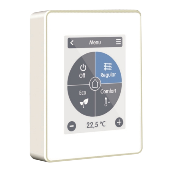
- Page 1 Installation and operating instruction Symondo Controller WLAN Read carefully before installation, commissioning and operation...
-
Page 2: Table Of Contents
Symondo Controller WLAN installation Example Controller-Connection Example CAN-Connection Operation Room Overview Operating Mode Menu Set Operation Hours Set Operation Hours Expert Menu Settings Devices Rooms Sensors Functions WiFi Access Point WiFi Sensor Service Values Symondo Controller WLAN and Symondo App Configuration Support Notes... -
Page 3: Safety Instructions
SAFETY INSTRUCTIONS EG-Conformity By affixing the CE mark to the unit the manufacturer declares that Symondo Controller WLAN conforms to the following relevant safety regulations: EU low voltage directive 2014/35/EU EU electromagnetic compatibility directive 2014/30/EU conforms. Conformity has been verified and the corresponding documentation and the EU declaration of conformity are kept on file by the manufacturer. -
Page 4: Warranty And Liability
Warranty and Liability The Unit has been manufactured and tested with regard to high quality and safety requirements. The warranty and liability shall not include, however, any injury to persons or material damage that is attributable to one or more of the following causes: Failure to observe these installation and operating instructions. -
Page 5: Description Symondo Controller Wlan
Installation Methods Wall installation, with/without wall socket Real Time Clock RTC with 24 hour power reserve Scope of Supply Symondo Controller WLAN 2 screws 3,5 x 35 mm and 2 plugs 6 mm for wall installation. Symondo Controller WLAN installation guide... -
Page 6: Installation
(strip cables max. 55 mm) and that any vein loops are fed back into the switch box, as unne- cessary vein loops in the Symondo Controller WLAN housing can lead to problems. Strip the last 8 - 9 mm of the wires. Isolate shielding and con- nect it at a suitable location (controller or CAN-box) to the pro- tective conductor. - Page 7 Refit the base and fasten with screw. Switch on the mains voltage and put Symondo Controller WLAN into operation. The setup wizard can be called up at any time in the Symondo Controller WLAN menu under...
-
Page 8: Example Controller-Connection
Example Controller-Connection Example CAN-Connection Only CAN in power supply from 4 cores of the regulator. The order and the number of devices (max. 50) is arbitrary. -
Page 9: Operation
Displayed as soon as an outdoor sensor is used on the HCC or an out- door sensor is activated on a Symondo Box in the menu "Expert > Symondo Box > Heating circuit > Sensor out- door". -
Page 10: Operating Mode
Operating Mode Overview > Operating Mode Menu Back/ Forward Navigate to the main menu Navigate back to the overview. Room Displays the selected space. Operating Modes The operating mode shown in colour is currently active and can be changed by selecting another mode. Manually selected modes remain active until the next change of mode by the timer pro- gram. -
Page 11: Set Operation Hours
Set Operation Hours Overview > Operating Mode > Menu > Timer Setting of individual heating and cooling times for the selected room. Separate times are set for the heating and cooling modes. To do this, first switch to the heating mode and define the corresponding times for this operating mode under Main menu >... -
Page 12: Set Operation Hours
Set Operation Hours Step 2 Select the first heating mode (Normal) - with the index finger select the desired length of time. The selected period will be coloured after selecting the colour of the operating mode Step 1 (normal = orange). Set the Use the arrow keys to select the times of the other operating desired day. -
Page 13: Expert Menu
5 seconds. Room Sync. If room synchronisation is activated, rooms set up on other Symondo Con- troller of the same network are also displayed on this Symondo Controller and vice versa. -
Page 14: Devices
Shows the type of connected device and its CAN ID. Remove devices Devices are removed from the net- work. Add a Symondo Sensor WLAN / Symondo Sensor WLAN to your net- work. For the commissioning of the Symondo Sensor WLAN / Symondo Sensor WLAN, please refer to the enclosed operating instructions. -
Page 15: Rooms
Rooms Overview > Operating mode > Menu > Expert > Settings > Rooms Add Room Adding rooms. Room 2 Setting the location, sensors and actu- ators of the respective room. Overview > Operating mode > Menu > Expert > Settings > Room 2 Location Selection of room icon. -
Page 16: Sensors
Sensors Overview > Operating mode > Menu > Expert > Settings > Rooms > Room 1 > Sensors > Temperature Icon Sensor already selected. Sensoricon with CAN ID + number Temperature sensor selection in the selected room. Overview > Operating mode > Menu > Expert > Settings > Rooms > Room 1 > Sensors > Humidity Sensoricon with CAN ID + number Humidity sensor selection in the selec- ted room. -
Page 17: Functions
Functions Overview > Operating mode > Menu > Expert > Settings > Functions Activate and set additional functions. Thermostat 1 Dehumidifier Season switch Timer 1 Fan coil 1 Overview > Operating mode > Menu > Expert > Settings > Functions > Thermostat 1 Switches the defined output to the set room / rooms depending on time and temperature. - Page 18 Overview > Operating mode > Menu > Expert > Settings > Functions > Dehumidifier The dehumidifier function switches the defined output depending on the set humidity in the set room(s). Output Assign the output to be switched by the Operating Mode function.
- Page 19 Overview > Operating mode > Menu > Expert > Settings > Functions > Timer 1 The function Timer 1-2 switches the defined output depending on the set times. Output Assign the output to be switched by the function. The other menu items become vis- ible after the output has been Timer assigned, as soon as at least one...
- Page 20 Overview > Operating mode > Menu > Expert > Settings > Functions > Fan coil 1 The fan coil function controls convection heating and cooling via the 0-10V/PWM outputs . Output Assign the output to be switched by the function. Operating Mode The other menu options become Set the operating mode of this con-...
-
Page 21: Wifi
Manage Access SSID Allow up to 5 users to access the unit Manually enter the WLAN name. via Symondo App by entering their e- mail addresses. WiFi Entering the WiFi password Activate DHCP If auto-configuration is enabled, the... -
Page 22: Access Point
Routing Mode The automatic routing independently selects between a direct connection of WiFi devices with the access point of the Symondo Controller and indirect WPS AP connection via the WLAN router. As Add a WPS-enabled repeater to not all routers support this function, increase the range. -
Page 23: Service Values
Connect Symondo Controller WLAN with the WLAN network: Expert Settings WiFi Choose Network Set the selected e-mail address to the access list in the Symondo Controller WLAN : Expert Settings WiFi "Access Control Log in to app with e-mail and password Enter the device address in the Symondo App. -
Page 24: Support
Has the electrical connection been made as described in the user manual? The heating/cooling circuit does not Is Symondo Controller WLAN assigned to the heating circuit in the controller menu? Is the CAN bus wiring between controller and Symondo Controller WLAN correct? respond to my Symondo Controller WLAN. - Page 25 Final Declaration Although these instructions have been created with the greatest possible care, the possibility of incorrect or incomplete information cannot be excluded. Subject as a basic principle to errors and technical changes. Date and time of installation: Name of installation company: Space for notes: MULTIBETON Produktions- und Vertriebsgesellschaft für Heizungs- und Energietechnik mbH...
Need help?
Do you have a question about the Controller WLAN and is the answer not in the manual?
Questions and answers