
Related Manuals for Symondo Controller


Summary of Contents for Symondo Controller
- Page 1 Installation and operating instruction Symondo Controller Read carefully before installation, commissioning and operation...
-
Page 2: Table Of Contents
CONTENT Safety Instructions EG-Conformity General Instructions Changes to the Unit Warranty and Liability Disposal and Pollutants Description Symondo Controller Technical Data Scope of Supply Installation Symondo Controller installation Example Controller-Connection Example CAN-Connection Operation Room Overview Operating Mode Menu Set Operation Hours... -
Page 3: Safety Instructions
SAFETY INSTRUCTIONS EG-Conformity By affixing the CE mark to the unit the manufacturer declares that Symondo Controller conforms to the following relevant safety reg- ulations: EU low voltage directive 2014/35/EU EU electromagnetic compatibility directive 2014/30/EU conforms. Conformity has been verified and the corresponding documentation and the EU declaration of conformity are kept on file by the manufacturer. -
Page 4: Warranty And Liability
Warranty and Liability The Unit has been manufactured and tested with regard to high quality and safety requirements. The warranty and liability shall not include, however, any injury to persons or material damage that is attributable to one or more of the following causes: Failure to observe these installation and operating instructions. -
Page 5: Description Symondo Controller
Other Specifications Installation Methods Wall installation, with/without wall socket Real Time Clock RTC with 24 hour power reserve Scope of Supply Symondo Controller 2 screws 3,5 x 35 mm and 2 plugs 6 mm for wall installation. Symondo Controller installation guide... -
Page 6: Installation
Symondo Controller housing can lead to problems. Strip the last 8 - 9 mm of the wires. Isolate shielding and con- nect it at a suitable location (controller or CAN-box) to the pro- tective conductor. Any contact between protective conductor and cir- cuit board can cause serious damage. - Page 7 The first and last unit in the CAN-network in series must be fitted with terminating resistance. The connection of the opposite side (controller) can be found in the corresponding terminal diagram in the controller manual. Refit the base and fasten with screw. Switch on the mains voltage and put Symondo Controller into operation.
-
Page 8: Example Controller-Connection
Example Controller-Connection Example CAN-Connection Only CAN in power supply from 4 cores of the regulator. The order and the number of devices (max. 50) is arbitrary. -
Page 9: Operation
Displayed as soon as an outdoor sensor is used on the HCC or an out- door sensor is activated on a Symondo Box in the menu "Expert > Symondo Box > Heating circuit > Sensor out- door". -
Page 10: Operating Mode
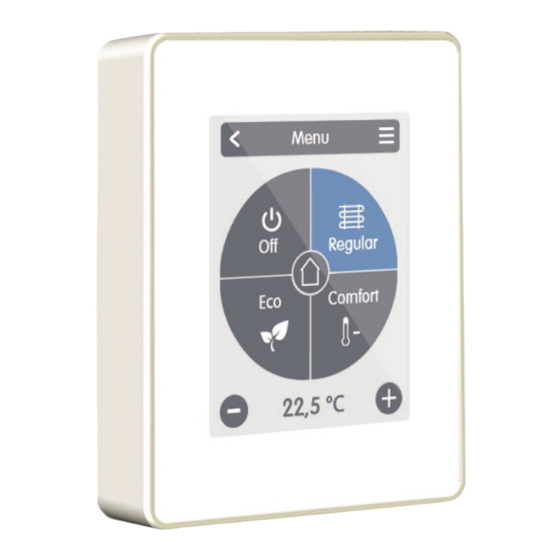
Operating Mode Overview > Operating Mode Menu Back/ Forward Navigate to the main menu Navigate back to the overview. Room Displays the selected space. Operating Modes The operating mode shown in colour is currently active and can be changed by selecting another mode. Manually selected modes remain active until the next change of mode by the timer pro- Reference temperature... -
Page 11: Set Operation Hours
Set Operation Hours Overview > Operating Mode > Menu > Timer Setting of individual heating and cooling times for the selected room. Separate times are set for the heating and cooling modes. To do this, first switch to the heating mode and define the corresponding times for this operating mode under Main menu >... -
Page 12: Set Operation Hours
Set Operation Hours Step 2 Select the first heating mode (Normal) - with the index finger select the desired length of time. The selected period will be coloured after selecting the colour of the operating mode Step 1 (normal = orange). Set the Use the arrow keys to select the times of the other operating desired day. -
Page 13: Expert Menu
Switch between full and restricted If room synchronisation is activated, menu. Only the reference tem- rooms set up on other Symondo Con- perature can be set in the mode "Hide troller of the same network are also menu". To return to "full" mode, press... -
Page 14: Devices
Devices Overview > Operating mode > Menu > Expert > Settings > Devices Clima systems have to be switched to 'heating' mode before another device can be added to a running system. Add Device Starts the search for new available devices in the network. -
Page 15: Rooms
Rooms Overview > Operating mode > Menu > Expert > Settings > Rooms Add Room Adding rooms. Room 2 Setting the location, sensors and actu- ators of the respective room. Overview > Operating mode > Menu > Expert > Settings > Room 2 Location Selection of room icon. -
Page 16: Sensors
Sensors Overview > Operating mode > Menu > Expert > Settings > Rooms > Room 1 > Sensors > Temperature Icon Sensor already selected. Sensoricon with CAN ID + number Temperature sensor selection in the selected room. Overview > Operating mode > Menu > Expert > Settings > Rooms > Room 1 > Sensors > Humidity Sensoricon with CAN ID + number Humidity sensor selection in the selec- ted room. -
Page 17: Functions
Seizing Protection Switching mode of the output If the seizing potection is activated Normal/Inverted. (daily, weekly, off), the controller switches on the outputs one after the other at 12:00 noon for 5 seconds to prevent seizing of the connected device during longer... - Page 18 Seizing Protection If the seizing potection is activated Room (daily, weekly, off), the controller Room selection for assigning the switches on the outputs one after the humidity of a room as the basis for other at 12:00 noon for 5 seconds to switching the dehumidifier.
- Page 19 Seizing Protection If the seizing potection is activated (daily, weekly, off), the controller switches on the outputs one after the other at 12:00 noon for 5 seconds to prevent seizing of the connected...
- Page 20 Signal to set target device to maximum power Seizing Protection If the seizing potection is activated (daily, weekly, off), the controller switches on the outputs one after the other at 12:00 noon for 5 seconds to prevent seizing of the connected...
-
Page 21: Service Values
Service Values Overview > Operating mode > Menu > Expert > Service values Message Log Displays the error memory. CAN Bus Status Display the CAN bus status. System Status Enables an update of all connected components. -
Page 22: Support
Has the electrical connection been made as described in the user manual? The heating/cooling circuit does not Is Symondo Controller assigned to the heating circuit in the controller menu? Is the CAN bus wiring between controller and Symondo Controller correct? respond to my Symondo Controller. - Page 23 Final Declaration Although these instructions have been created with the greatest possible care, the possibility of incorrect or incomplete information cannot be excluded. Subject as a basic principle to errors and technical changes. Date and time of installation: Name of installation company: Space for notes: MULTIBETON Produktions- und Vertriebsgesellschaft für Heizungs- und Energietechnik mbH...
Need help?
Do you have a question about the Controller and is the answer not in the manual?
Questions and answers