
Related Manuals for Symondo Box


Summary of Contents for Symondo Box
- Page 1 Symondo Box Heating circuit controller for surface heating and cooling Installation and operating instruction Read carefully before installation, commissioning and operation...
-
Page 2: Table Of Contents
CONTENT Safety Instructions EU-Conformity General Instructions Explanation of Symbols Changes to the Unit Warranty and Liability Disposal and Pollutants Description Symondo Box Description Technical Data Scope of Supply Installation Wall Installation Electrical Connection Electrical Terminals LED status Wiring structures CAN bus 1-Wire-Bus Connection examples S ymondo Controller Connection example single-family house with >8 zones Connection example apartment building Connection Examples 1-Wire Sensors Connection example Symondo Sensor 1-Wire ID overview Setup Wizard Operation Room Overview Operating Mode Menu Set Operation Hours Set Operation Hours Expert Menu Settings... -
Page 3: Safety Instructions
Safety Instructions EU-Conformity By affixing the CE mark to the unit the manufacturer declares that theSymondo Box conforms to the following relevant safety reg- ulations: EU low voltage directive 2014/35/EU EU electromagnetic compatibility directive 2014/30/EU EU RoHS Directive 2011/65/EU EU WEEE Directive 2012/19/EU (Reg.nr. DE 23479719) conforms. Conformity has been verified and the corresponding documentation and the EU declaration of conformity are kept on file by the manufacturer. General Instructions Please read carefully! These installation and operating instructions contain basic instructions and important information regarding safety, installation, com- missioning, maintenance and the optimal use of the unit. Therefore these instructions must be read and understood completely by the installation technician/specialist and by the system user before installation, commissioning and operation of the unit. This unit is an automatic, electrical Heating circuit controller for surface heating and cooling for and similar applications. Install the unit only in dry areas and under the ambient conditions described in “Specifications”. The valid accident prevention regulations, VDE regulations, the regulations of the local power utility, the applicable DIN-EN standards and the installation and operating instruction of the additional system components must also be observed. Under no circumstances does the unit replace any safety devices to be provided by the customer! Installation, electrical connection, commissioning and maintenance of the device may only be carried out by an appropriately trained specialist. Users: Make sure that the specialist gives you detailed information on the function and operation of the unit. Always keep these instructions in the vicinity of the unit. The manufacturer does not take over any liability for damage caused through improper usage or non-compliance of this manual! Explanation of Symbols Failure to observe these instructions can result in electrocution. -
Page 4: Changes To The Unit
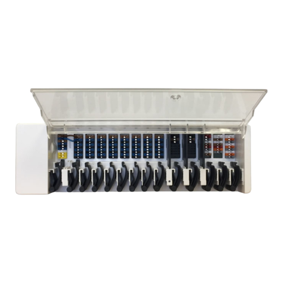
Improper installation, commissioning, maintenance and operation. Improperly executed repairs. Unauthorised structural changes to the unit. Use of the device for other than its intended purpose. Operation above or below the limit values listed in the ‚Specifi cations‘ section. Force majeure. Disposal and Pollutants The unit conforms to the European RoHS 2011/65/EU for the restriction of the use of certain hazardous substances in electrical and elec- tronic equipment. Under no circumstances may the device be disposed of with the normal household waste. Dispose of the unit only at appro- priate collection points or ship it back to the seller or manufacturer. Description Symondo Box Description The Symondo Box is a universal heating and individual room controller for surface heating and surface cooling systems. In com-bination with up to 8 Symondo Controller, this enables efficient use and function control of your surface heating and cooling with intuitive operation. The inputs and outputs can be S ymondo Controller freely assigned, so that different heating and cooling systems can be implemented. Important characteristics of the Symondo Box: Control of 8 heating and cooling zones with 1 - 4 actuators Measurement of room temperature and humidity in combination with Symondo Controller, Symondo Sensor or Symondo Sensor optionally weather compensated via outdoor temperature sensor optional control of heating circuit pump and mixer (PWM oder 0-10V) possible ... -
Page 5: Technical Data
Technical Data Model Symondo Box Heating circuit controller for surface heating and cooling Temperature controller class (ErP) Energy efficiency (ErP) Standby loss 0,5W Request type invertible heat "On /off" and/or "modulating" pump Electrical specifications: Power Supply 230 VAC (+/- 5%), 50 - 60 Hz Power consumption / standby 0,5 - 2,5W/ 0,5W Internal fuse 1 (Pos. A, left) 2A slow 250V Fuse protection for terminal area A and electronics Internal fuse 2 (Pos. B, right) 4A slow 250V Fuse protection for terminal area B - I Protection Class IP20 Protection class / overvoltage category II / II Inputs Quantity Measuring range / design... -
Page 6: Scope Of Supply
Scope of Supply Heating circuit controller for surface heating and cooling Symondo Box 2 Replacement fuses additional separation wall for use of non-230V AC actuators DIN rail H=35mm L=280mm 2 screws 3,5 x 35 mm and 2 dowels S6 Symondo Box installation and operating instructions Installation Wall Installation Fix the DIN rail horizontally to the wall using screws. Installation 1. Place the Symondo Box on the upper edge of the DIN rail with the locking catch on top. 2 Engage the device by pressing it down. Ensure that the locking catches engage completely and that the device is firmly seated on the rail. Disassembly Remove the Symondo Box from the DIN rail by insert-ing two screwdrivers into the eyelets and pulling them down- wards. Separation walls and cover The separation walls and the cover can be removed for easier connection of the cables. They must then be reinstalled in order to safely separate areas carrying mains voltage from areas carrying low voltages. Open the cover (90° degree) and then pull it out of the side of ... -
Page 7: Electrical Connection
Electrical Connection Low-voltage cables such as temperature sensor cables must be routed separately from mains voltage cables. Before working on the unit, switch off the power supply and secure it against being switched on again! Check that there is no power flowing! Electrical connections may only be made by a specialist and in compliance with the applicable reg- ulations. The unit may not be put into operation if there is visible damage to the housing, e.g. cracks. The customer must provide an all-pole disconnecting device, e.g. an emergency heating switch. The strain reliefs are suitable for flexible cables with a cable sheath diameter of 5 mm to 8 mm, primarily using the lower strain relief (as shown). The cables must be checked for firm placement. Solid, thicker and thinner cables must always be laid firmly and must be fixed on the installation side. Massive wires or cables with special wire end sleeves can simply be pressed into the ter- minals. For other wires, the trowel must first be completely pressed on with a screwdriver as shown. Wire ferrules made of brass can be difficult to clamp due to their asym- metric crimping shape. In this case, remove the wire ferrule. The plug-in terminals are also suitable for flexible cables. ... -
Page 8: Electrical Terminals
8 PE CAN low 9 PE Example Wiring of Terminal Blocks Mains connection heating circuit pump Actuators for the heating zones Potential-free switching contacts for additional functions Symondo Controller in the private CAN bus Private CAN bus For linking devices within a housing unit, such as a single-family house or a flat. Shares all information with all devices in the same network, including room names, setpoint temperatures, absences, etc. -
Page 9: Led Status
0-10V/PWM outputs for additional functions Building CAN bus and 1-Wire sensors Building CAN bus For linking devices across several units, such as flats, offices or hotel rooms. Only shares information relevant for optimising the overall system: - Outdoor temperature - Energy demand - Flow temperature - Season (heating / cooling) LED status LED A Lights up if mains voltage is present and relay A is switched LED B - K Lights up, if relay B - K is switched. LED L Flashes, if the private CAN bus is active. Flashes at 1Hz (60x / minute) if there is an error in the private CAN bus. LED M Lights up when the building CAN bus and the 1-wire bus are active. Flashes at 1Hz (60x / minute) if there is an error in the building CAN bus. Flashes at 3Hz (180x / minute) if there is an error in the 1-wire connection. EXCEPTION: If the building CAN bus remains unused, a flashing (1Hz (60x / minute)) of LED M is normal and does NOT mean that there is a fault. LED N Lights up, if outputs V1, V2 or V3 are active. -
Page 10: Wiring Structures
Wiring structures CAN bus Description Implementation Admissibility Line Yes, optimal installation with maximum range. Tree Star 1-Wire-Bus Description Implementation Admissibility Line Yes, optimal installation with maximum range. Tree Possible without guarantee for small systems with short line lengths and few network participants. Keep stub lines short. Star Not recommended... -
Page 11: Connection Examples Symondo Controller
Connection examples Symondo Controller Do not combine units designed for heating only (Symondo Controller/Symondo Box) with units designed for heating and cooling only (Symondo Controller/Symondo Box). Example 1: Line structure with Symondo Box as end point. A 120 Ohm terminating resistor must be set on the first and last device in the CAN network. Example 2: Line structure with Symondo Box in the middle. A 120 Ohm terminating resistor must be set on the first and last device in the CAN network. -
Page 12: Connection Example Single-Family House With >8 Zones
Connection example single-family house with >8 zones Example: Line structure with several Symondo Box via the private CAN bus (e.g. within a residential unit). A 120 Ohm terminating resistor must be set on the first and last device in the CAN network. -
Page 13: Connection Example Apartment Building
Connection example apartment building Example: Line structure with several Symondo Box via the building CAN bus (e.g. across several residential or com- mercial units). Use building CAN bus on terminal block M so that no private data such as room temperatures or holiday mode are shared across flats. A 120 Ohm terminating resistor must be set on the first and last device in the CAN network. -
Page 14: Connection Examples 1-Wire Sensors
Connection Examples 1-Wire Sensors When connecting the 1-Wire sensors, please record the 16-digit 1-Wire ID and the location of the sensor for later commissioning of the system! The 1-Wire ID can be found in the device housing and in the device menu under: Devices -> Symondo Box -> Resources -> 1-Wire Sensor. Example 1: Line. The installation leads from one sensor to the next. A twisted pair cable must be used for the connecting cable. Example 2: Tree Structure. A twisted pair cable must be used for the connecting cable. -
Page 15: Connection Example Symondo Sensor
Connection example Symondo Sensor Example line: The installation leads from one sensor to the next. A twisted pair cable must be used for the connecting cable. The 1-Wire system must be designed with 3 wires (5VDC, DQ, GND). The total cable length can thus be up to 100m. A suitable twis- ted pair cable must be used and sufficient wire cross-section must be ensured, e.g. with LIYCY 2 x 2 x 0.75mm², in order to avoid impermissible voltage drop at the Symondo Sensor below U = 4.5VDC. -
Page 16: 1-Wire Id Overview
1-Wire ID overview For systems with 1-Wire sensors, you must assign the respective 1-Wire ID to a room on the Symondo Controller. Writing down the IDs in combination with the room in which the sensor hangs in the following list simplifies the later assignment. The 1-Wire ID can be found inside the sensor on the type plate (1) and on (1) the supplied sticker (2). We recommend to insert the sticker into the fol- lowing table. (2) 1-Wire Raumsensor Clima Symondo Pipe Sensor Symondo Floor Sensor Symondo Outside Sensor Location 1-Wire ID Location 1-Wire ID Example Bathroom 1053f67c0308009e ... -
Page 17: Setup Wizard
Setup Wizard The commissioning wizard in the Symondo Controller starts automatically when the unit is commissioned for the first time and guides you through the necessary basic settings in the correct order. Press the arrow keys in the upper right/left corner to return to the next or previous setting. Commissioning must also be completed on all other Symondo Controller in the network. The Symondo Box is configured exclusively on aSymondo Controller . The setup wizard is restarted via the "Factory settings" menu item. Operation To parameterise the Symondo Box, you need at least one Symondo Controller. This is connected to the Symondo Box via the private CAN bus as described above (see "Electrical Connection" on page 7). Room Overview Displays the room temperature, humidity and external temperature once the start screen was activated. Room icon % Room humidity ... -
Page 18: Operating Mode
Operating Mode Overview > Operating Mode Back/ Forward Menu Navigate back to the overview. Navigate to the main menu Room Operating Modes Displays the selected space. The operating mode shown in colour is cur- rently active and can be changed by select- ing another mode. Manually selected modes remain active until the next change Reference tem- of mode by the timer program. A back- perature ground frost protection function remains ... -
Page 19: Set Operation Hours
Set Operation Hours Overview > Operating Mode > Menu > Timer Setting of individual heating and cooling times for the selected room. Separate times are set for the heating and cooling modes. To do this, first switch to the heating mode and define the corresponding times for this operating mode under Main menu > Timer. Then change to the cooling mode and define the corresponding times for this operating mode under Main menu > Timer. Menu Opens the copy function. The function allows you to copy the heating and cooling times to the following day, to Operating Modes Monday - Friday or to Monday - Selection of the operating mode to Sunday. select individual heating or cooling sections. Clock Time table of the selection in periods of 30 minutes increments. Touch indi- vidual segments, or drag your finger over complete time intervals to colour Back / Next them according to the selected oper- Weekday Selection of the day which is ation mode. to be set. -
Page 20: Expert Menu
Expert Menu Overview > Operating Mode > Menu > Expert Select Language Set the device language. Date & Time Setting of time and date and automatic summer/winter time changeover. Settings Parameterisation of heating/cooling Service Values system. Information about the system. -
Page 21: Settings
Symondo Box Assignment and configuration of addi- Assignment and configuration of addi- tional functions for the 0-10V/PWM tional functions of the free switching outputs in the Symondo Controller. outputs on the Symondo Box. This menu is only visible if this Zones Symondo Controller was set as the "configurator" of the Symondo Assign rooms to heating and cooling Box during commissioning. zones. WiFi Set and manage WiFi functions. Display Brightness Setting the screen brightness. -
Page 22: Devices
Description devices in the network. Displays the detected type of the device. Device icon Shows the type of connected device Remove devices and its CAN ID. Devices are removed from the net- work. Overview > Operating mode > Menu > Expert > Settings > Devices > Symondo Box Resources Displays which outputs and connected sensors are available. Symondo Box Factory settings Use this Symondo Controller to con- figure the Symondo Box. Tip: If avail- Load the factory settings of the able, set the Symondo Controller with Symondo Box. Remove Remove WiFi. device from list. ... -
Page 23: Rooms
Rooms Overview > Operating mode > Menu > Expert > Settings > Rooms Add Room Adding rooms. Room 2 Setting of location, sensors of the respective room. Overview > Operating mode > Menu > Expert > Settings > Room 2 Temperature Location Selection of the temperature sensors Selection of room icon. in the selected room. Modulation Humidity Hysteresis Selection of humidity sensors in the Switch-off hysteresis for the room set- selected room. point temperature. Zones Dew point correction ... -
Page 24: Temperature / Humidity
Temperature / Humidity Overview > Operating mode > Menu > Expert > Settings > Rooms > Room 1 > Temperature Sensor icon with CAN Icon ID + resource no. Sensor already selected. When using 1-Wire sensors, these are displayed via the CAN ID of the Symondo Box + a resource number. With 1-Wire sensors, the temperature and the 1-Wire ID are displayed altern- ately. The 1-Wire ID is used for the unique assignment of the sensors. Overview > Operating mode > Menu > Expert > Settings > Rooms > Room 1 > Humidity ... -
Page 25: Functions Symondo Controller
Functions Symondo Controller Overview > Operating mode > Menu > Expert > Settings > Symondo Controller Activate and set additional functions on free outputs of the Symondo Controller. ... -
Page 26: Functions Symondo Box
Functions Symondo Box Overview > Operating mode > Menu > Expert > Settings > Symondo Box Activate and set additional functions on free outputs of the Symondo Box. Further functions on the next page. Overview > Operating mode > Menu > Expert > Settings > Symondo Box > Thermostat 2 Switches the defined output to the set room / rooms depending on time and temperature. Output Assign the output to be switched by ... - Page 27 Overview > Operating mode > Menu > Expert > Settings > Symondo Box > Dehumidifier The dehumidifier function switches the defined output depending on the set humidity in the set room(s). Output Assign the output to be switched by the function. The other menu Operating Mode options become visible after assigning the output. Specify in which operating states of Modulation Humidity the heating and cooling system the dehumidifier is to be switched on. Set the limit value for the air humid- Hysteresis ity. If this is exceeded, the dehu- midifier is switched on. Define the switch-off hysteresis. Room Seizing Protection Room selection for assigning the ...
- Page 28 Overview > Operating mode > Menu > Expert > Settings > Symondo Box > HC mixer The heating circuit mixer function controls the flow temperature via a 0-10V / PWM mixer depending on the outdoor temperature. Output Assign the output to be switched by the function. The other menu Output closed / Signal options become visible after type assigning the output. Select switching output. Relay or sig- Only outputs N1, N4 and N8 may nal output. Relay, 0-10V or PWM. be used. Turn Time Direction ...
- Page 29 assigning the output. Outdoor sensor By default, the output at ter- Assignment of the outdoor sensor for minal block A of the Symondo weather-compensated control of the Box is defined here. heating circuit. Follow-up time Curve When all zones are switched off, ...
- Page 30 Appears when a sensor has been defined for "Flow". Setting the maximum flow temperature in the "Cooling" mode. Dew Point protection This feature activates the switch-off of the heating circuit pump when the actual flow temperature falls below the set flow temperature by 1° C for 5 minutes. The controller automatically adjusts the set flow temperature based on the rel- ative humidity in the rooms to prevent mould formation in cooling mode. Season switch External season switch (between heat- ing and cooling) via selected output. Seizing Protection If the Seizing Protection is activated (daily, weekly, off), the controller switches on the outputs at 12 o'clock one after the other for 5 seconds in order to prevent the connected unit from seiz- ing in case of longer standstill. ...
- Page 31 Tmax Drain Set the maximum temperature in the energy absorber. Seizing Protection If the seizing potection is activated (daily, weekly, off), the controller switches on the outputs one after the other at 12:00 noon for 5 seconds to prevent seizing of the connected device during longer inactivity. Overview > Operating mode > Menu > Expert > Settings > Symondo Box > Season switch The "season switch" function switches when the system changes from heating mode to cooling mode, see "Menu" on page 18 Output Assign the output to be switched by Room the function. The other menu options become visible after Room selection to start the function. assigning the output. As soon as one of the assigned rooms switches from "heating" mode Seizing Protection to "cooling" mode the season switch ...
- Page 32 Overview > Operating mode > Menu > Expert > Settings > Symondo Box > Timer 2 The function Timer 1-2 switches the defined output depending on the set times. Output Assign the output to be switched by the function. The other menu Release Times options become visible after assigning the output. Set the times at which the outputs are Seizing Protection to be switched. If the seizing potection is activated (daily, weekly, off), the controller switches on the outputs one after the other at 12:00 noon for 5 seconds to prevent seizing of the connected device during longer inactivity. Overview > Operating mode > Menu > Expert > Settings > Symondo Box > Energy request The function energy request switches the defined output when the rooms require energy depending on the set delay. Relay Modus Set the relay modes ''Switching'' or Output ''Modulating''. In the ''switch'' mode the ...
- Page 33 Overview > Operating mode > Menu > Expert > Settings > Symondo Box > Fan coil 1 The fan coil function controls convection heating and cooling via the 0-10V/PWM outputs . Output Assign the output to be switched by the function. The other menu Operating Mode options become visible after assigning the output. Set the operating mode of this con- Flow vector function. Heating, cooling, or heating and cooling. Assignment of the convector flow Delay sensor in "Heating" mode. Delays the switching on of the fan Room coil so that it does not push against closed valves. Selection of the sensors on whose ...
-
Page 34: Zones
Zones verview > Operating mode > Menu > Expert > Settings > Zones Zones Selection of heating zone to be set or managed. Overview > Operating Mode > Main Menu > Expert > Settings > Zones > Zone B Room Assignment of the rooms in which the zone is located. First, rooms must be created in the menu under: Expert -> Rooms. Operating Mode S/W Day Set the operating mode of this zone. Setting the temperature limit for sum- Heating, cooling, or heating and cool- mer switch-off in "Normal" operating ing. mode in heating mode. If the outdoor S/W Eco temp. exceeds this value, this zone is no longer heated. Setting the temperature limit for sum- Relay Modus mer switch-off in "Eco" operating mode ... -
Page 35: Example Zone Setting
Example zone setting Step 1 Select the respective zone. Step 2 Select the room cor- responding to the zone. Step 3 Step 4 Set the desired outdoor Set the desired outdoor switch-off temperature for switch-off temperature for the Normal (S/W Day) mode. Eco (S/W Eco) mode. -
Page 36: Wifi
WiFi Overview > Operating mode > Menu > Expert > Settings > WiFI This menu is only available when a Symondo Controller WLAN or Symondo Controller WLAN is connected. Activate WiFi WiFi status Activate WiFi function. Information about WiFi status and Select Network device address (which is required to connect to the Symondo App). Scan for available networks and select the network. Manage Access SSID Allow up to 5 users to access the unit via Symondo App by entering their e- Manually enter the WLAN name. mail addresses. WiFi password Entering the WiFi password Activate DHCP If auto-configuration is enabled, the device searches the network for a ... -
Page 37: Service Values
Display the CAN bus status. System Status System Status Displays the system status. Update all components in the sys- tem (from software version 32480). Symondo Controller WLAN and Symondo App Configuration Download Symondo App app to your mobile device. Currently available on Google Play (Android) and Apple App Store (iOS). Start app and create account. Click activation link in your e-mail inbox. Connect Symondo Controller with the WLAN network: Expert Settings WiFi Choose Network Add selected e-mail address to the access list in Symondo Controller: Expert Settings WiFi Access control Log in to app with e-mail and password If your Symondo Controller WLAN is located in the same WiFi network as your mobile device, you can activate it by clicking the "Done! Search Symondo Controller on WiFi to connect to each other. -
Page 38: Tips
Tips Interface Mode Menu > Expert > Settings > Interface mode see "Settings" on page 21 Provides the option to restrict the menu against unintentional use, for example, by hotel guests or children. Download firmware updates via Offers the possibility to update Symondo Controller and Symondo Box in the network to the latest WiFi (only with Symondo Con- version. Symondo Box: Menu > Expert > Settings > Devices > Symondo Box > Firmware Symondo troller WLAN) Controller: Menu > Expert > Service values > System update, start update on each Symondo Con- see "Devices" on page 22 troller. It is recommended to check for the availability of system update from Symondo Controller and Symondo Box during installation. Insulation factor Menu > Expert > Settings > Symondo Box > Heating circuit > Insulation factor see "Functions Symondo Box" on Provides the option to adapt the flow temperature calculation performed by the controller to the page 26 insulation of your building. Dew Point protection Menu > Expert > Settings > Symondo Box > Heating circuit > Dew point monitoring see "Functions Symondo Box" on Switch-off of the heating circuit if the flow temperature falls below the permitted flow temperature page 26 for a safe cooling operation (mould prevention) for more than 5 minutes, depending on the humid- ity. -
Page 39: Support
Support Event Support Devices or sensors are missing Has a search for connected devices been carried out under Settings > Devices > Add from the device or sensor lists Device? Has the electrical connection been implemented as described in the operating instructions? although they are connected. Is the bus connection properly installed? see "Wiring structures" on page 10 A specific sensor is not found, fluc- Check wiring, check correct connection. Measure the voltage at the sensor (supply voltage tuating sensor values 5V DC), install the 1-Wire repeater / extender if necessary, carry out the system update. No sensor is found Check wiring, disconnect 1-Wire sensors, start with the last sensor in the series. Pay atten- tion to when a sensor is displayed. Measure the voltage at the last sensor (supply voltage 5V DC), install 1-Wire repeater / extender if necessary, carry out system update. - Page 40 Notes ...
Need help?
Do you have a question about the Box and is the answer not in the manual?
Questions and answers