Advertisement
Quick Links
Advertisement

Related Manuals for Totnz TZCT1B


Summary of Contents for Totnz TZCT1B
- Page 1 INSTRUCTION MANUAL Rev01(A) TZCT1B / TZCT1V / TZCT1M Lift Top Coffee Table service.wowowo@gmail.com...
- Page 2 Contents ① ⑨ ⑨ ⑧ ⑩ ④ ⑦ ② ⑥ ② ⑤ ⑦ ③ ⑧ ⑪ ⑫ ⑩ ⑨ A x 1 B x 1 C x 24 D x 24 E x 6 M6 x 12mm M3.5 x 14mm M3.5 x 25mm M3.5 x 35mm F x 8...
- Page 3 Tools Needed (NOT lncluded) Phillips Screwdriver Rubber Mallet Cam Lock System Operation 1. Screw the cam bolt [C] into the threaded insert on the panel. 2. Connect both panels together. Make sure cam bolt [C] goes into the small pre-drilled hole on the end of the panel. 3.
- Page 4 STEP 1 ② Phillips Screwdriver (NOT lncluded) ④ ② ③ NOTE: Keep the grooves on the panels ② ③ ④ are at the same level. ②*1 ③*1 ④*1 C*2 J*4...
- Page 5 STEP 2 Phillips Screwdriver (NOT lncluded) ⑤ ⑪ NOTE: Make sure the four big holes point to the bottom in this step. ⑤*1 ⑪*1 J*3...
- Page 6 STEP 3 Phillips Screwdriver (NOT lncluded) ⑪ ⑤...
- Page 7 STEP 4 ⑥ ⑥*1...
- Page 8 STEP 5 ② ② ②*1 C*2 D*2 J*4...
- Page 9 STEP 6 Phillips Screwdriver (NOT lncluded) ⑪ ⑫ NOTE: Keep these big holes ⑫*1 J*3 point to outwards in this step.
- Page 10 STEP 7 ⑦ ⑧ Please NOTE that there is NO pilot hole for furniture sliders. Please use a rubber mallet and gently tap them right into place. ⑦ ⑧ Phillips Screwdriver (NOT lncluded) Rubber Mallet (NOT lncluded) Make sure these holes ⑦*2 ⑧*2 C*10 D*6 F*4 face down in this step.
- Page 11 STEP 8 ⑨ ⑩ Please NOTE that there is NO pilot hole for furniture sliders. Please use a rubber mallet and gently tap them right into place. ⑨ ⑩ Phillips Screwdriver (NOT lncluded) Rubber Mallet (NOT lncluded) Make sure these holes ⑨*2 ⑩*2 C*10 D*6 F*4 face down in this step.
- Page 12 STEP 9 ⑦ Phillips Screwdriver (NOT lncluded) ⑧ ⑨ ⑩ ⑫ ⑩ ⑨ ⑧ ⑦...
- Page 13 STEP 10 Phillips I*16 Screwdriver (NOT lncluded)
- Page 14 STEP 11 Phillips Screwdriver (NOT lncluded) ① ①*1 E*6 H*6...
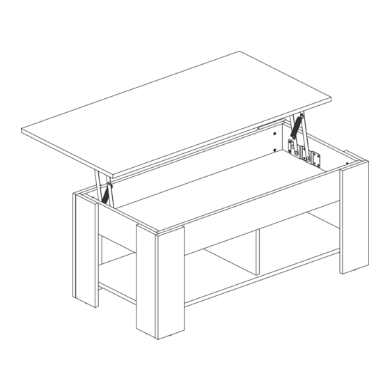
- Page 15 STEP 12 Phillips NOTE: Ensure the spring points to inwards and the two Screwdriver vertical frames are close to the front side of the top panel (NOT lncluded) ① in this step. Vertical Frame Front ① ① A*1 B*1 G*4 H*4...
- Page 16 STEP 13 Phillips Screwdriver (NOT lncluded) You may need assistance with this step. Please refer to the correct installation method, pay attention to the gap between the upper panel and the table legs. H*12 860-00427-00 Rev01...
Need help?
Do you have a question about the TZCT1B and is the answer not in the manual?
Questions and answers