Sign In
Upload
Download
Table of Contents
Contents
Add to my manuals
Delete from my manuals
Share
URL of this page:
HTML Link:
Bookmark this page
Add
Manual will be automatically added to "My Manuals"
Print this page
×
Bookmark added
×
Added to my manuals
Manuals
Brands
MBL Manuals
Amplifier
Corona C31
Owner's manual
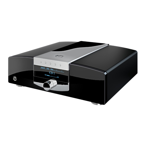
MBL C31 Owner's Manual
Cd-dac, preamplifier, integrated amplifier, stereo power amplifier, mono power amplifier
Hide thumbs
Also See for C31
:
Owner's manual
(63 pages)
1
2
Table Of Contents
3
4
5
6
7
8
9
10
11
12
13
14
15
16
17
18
19
20
21
22
23
24
25
26
27
28
29
30
31
32
33
34
35
36
37
38
39
40
page
of
40
Go
/
40
Contents
Table of Contents
Bookmarks
Table of Contents
Table of Contents
Precautionary and Safety Measures
Disposal
Warranty
Package Contents
What You Still Need
Device Diagrams
CD-Dac C31
Preamplifier C11
Integrated Amplifier C51
Stereo Power Amplifier C21
Mono Power Amplifier C15
Connection Diagram
Combination CD-DAC C31 and the Integrated
Amplifier C51
Connecting the CD-DAC C31 to the Integrated
Wiring the Loudspeakers
Combination CD-DAC C31, Preamplifier C11 and
Stereo Power Amplifier C21
Wiring The CD-Dac C31 With The Preamplifier C11
Wiring The Preamplifier C11 With The Stereo
Power Amplifier C21
Wiring the Speakers
Combination CD-DAC C31, Preamplifier C11 and
Mono Power Amplifier C15
Wiring The CD-Dac C31 With The Preamplifier C11
Wiring the Speakers
Connecting the Smartlink
Wiring the Power Cables
General Functions
Turning Your Equipment on and off
MBL Smartlink
Display Brightness
Standby
Function Buttons
Menu Navigation
C31 Menu Navigation
Menu
DIM Standby
Info
Factory Default
C11 / C51 Menu Navigation
Menu
Input Setup
C31 Input Mapping
Input Name
Volume Cut
DIM Standby
Info
Factory Default
C15 Menu Navigation
Menu
Input Setup
DIM Standby
Info
Factory Default
Remote Control
CD-Dac C31
Preamplifier C11
Integrated Amplifier C51
Stereo Power Amplifier C21
Mono Power Amplifier C15
Firmware Update
Cleaning Your Equipment
Advertisement
Quick Links
1
Preamplifier C11
Download this manual
CD-DAC C 31
PREAMPLIFIER C 11
INTEGRATED AMPLIFIER C 51
STEREO POWER AMPLIFIER C 21
MONO POWER AMPLIFIER C 15
Owner's Manual
English
Table of
Contents
Previous
Page
Next
Page
1
2
3
4
5
Advertisement
Table of Contents
Need help?
Do you have a question about the C31 and is the answer not in the manual?
Ask a question
Questions and answers
Related Manuals for MBL C31
Amplifier MBL Corona Line Owner's Manual
(63 pages)
Amplifier MBL Corona C11 Owner's Manual
Cd-dac, preamplifier, integrated amplifier, stereo power amplifier, mono power amplifier (40 pages)
Amplifier MBL Corona C51 Owner's Manual
Cd-dac, preamplifier, integrated amplifier, stereo power amplifier, mono power amplifier (40 pages)
Amplifier MBL Corona C21 Owner's Manual
Cd-dac, preamplifier, integrated amplifier, stereo power amplifier, mono power amplifier (40 pages)
Amplifier MBL Corona C15 Owner's Manual
Cd-dac, preamplifier, integrated amplifier, stereo power amplifier, mono power amplifier (40 pages)
Amplifier MBL 6010 D Owner's Manual
Mbl reference line 6010 d preamplifier owner's manual (42 pages)
Amplifier MBL 9007 Owner's Manual
Mono/stereo power amplifier (49 pages)
Amplifier MBL REFERENCE Series Owner's Manual
(20 pages)
This manual is also suitable for:
C11
C51
C21
C15
Table of Contents
Print
Rename the bookmark
Delete bookmark?
Delete from my manuals?
Login
Sign In
OR
Sign in with Facebook
Sign in with Google
Upload manual
Upload from disk
Upload from URL


Need help?
Do you have a question about the C31 and is the answer not in the manual?
Questions and answers