Table of Contents
Advertisement
Available languages
Available languages
Quick Links
Advertisement
Chapters
Table of Contents

Related Manuals for Optimus Compact


Summary of Contents for Optimus Compact
-
Page 4: Table Of Contents
CONNECTION OF PERIPHERALS TO THE CAN BUS ........................9 5.1. CAN Bus transmission speed configuration ......................... 10 5.2. Connection between the COMPACT and COMPACT-E units ..................11 5.3. Connection between COMPACT and CAN peripherals ....................12 INSERTING THE CARDS................................. 12 UMX-C16 ..................................... -
Page 5: Introduction
The 8 remaining slots are available for inserting cards UMX-C16, UMX-EA3, UMX-2M3, UMX-2SA, UMX-2SB, UMX-MC6 or UMX-LNK. The capacity of the matrix may be expanded using COMPACT-E units (10 slots per unit) up to a maximum of 10 units. The COMPACT-E units allow housing cards UMX-2SA, UMX-2SB, UMX-MC6, UMX-C16 or UMX-LNK/E. -
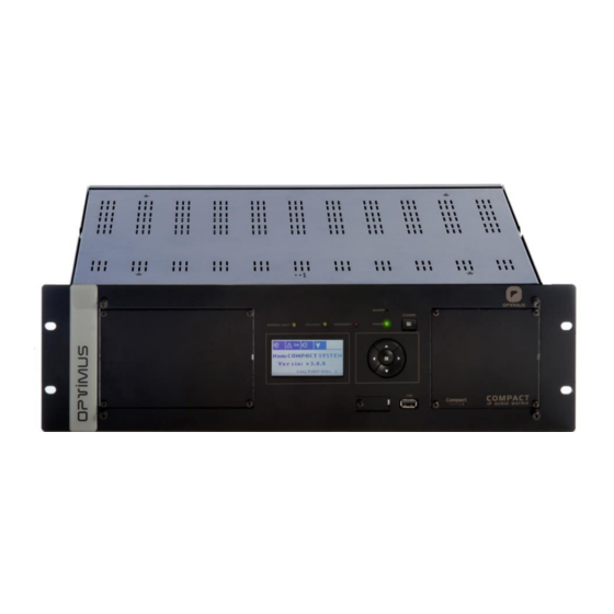
Page 6: Front View
(Fireman’s panel and voice alarm manual control). Emergency Mode. (9) Display. (4) Buzzer. The COMPACT incorporates a buzzer that (10) CONSOLE connector. Mini USB connector. Allows generates an acoustic signal when an alarm is received. monitoring the system. Only specialised personnel. -
Page 7: Power And Control Module
Is used in a redundant network as a secondary connection to the IP network. CAN Contacts Data communication bus between the COMPACT matrix, the COMPACT- E slave and CAN peripherals. For the connection of the CAN bus it is recommended to use a shielded twisted pair AWG24 cable. - Page 8 SW1. CONFIGURATION OF THE OUTPUT CONTACTS Figure 10 CONTACT B DIPSWITCH A/B DRY REFERENCED TO PRIMARY NUMBER CONTACT (*) GROUND POWER OUTPUT CONTACT 1 OUTPUT CONTACT 2 OUTPUT Figure 11 CONTACT 3 SECONDARY POWER * FACTORY SETTINGS COMPACT version 5.0.002 R +D Department...
-
Page 9: Placement Of The Battery
10) BUS AUDIO LINK Audio bus expansion connector. it is used for connecting the COMPACT to the COMPACT-E units. To accomplish this use 34 way flat ribbon cable with 2x17, 2.54mm IDC connectors. When installing the cable be careful to install the connectors in the same position and side of the flat ribbon cable (see figure 16). - Page 10 Remove the control module. Figure 13 Insert the battery respecting the polarity indicated in the attached drawing (positive + at the top). Figure 14 Once placed, insert the control module again and turn on the power. COMPACT version 5.0.002 R +D Department...
-
Page 11: Connection Of Peripherals To The Can Bus
With the rest of CAN peripherals of the installation (MD-30C, ME-200C, NS-CAN ...) and with an internal speed adapter that the COMPACT device has built-in, the transmission speed is 33.3 kbit/s. This lower speed makes it possible to reach greater distances in the connection between the peripherals and the central one. -
Page 12: Can Bus Transmission Speed Configuration
PC must match. Otherwise, the network settings of the PC or the COMPACT must be changed in order to be in the same range (for example, the PC could have an IP address of 10.1.100.152). See section 12.1. Configuration of the COMPACT network addresses. -
Page 13: Connection Between The Compact And Compact-E Units
5.2. Connection between the COMPACT and COMPACT-E units Use the BUS AUDIO LINK and the CAN BUS contacts to connect the COMPACT matrix to the COMPACT-E units. By default, the transmission speed of the CAN bus of the COMPACT unit is 500 kbit/s. -
Page 14: Connection Between Compact And Can Peripherals
6. INSERTING THE CARDS The COMPACT model incorporates a standard issue UMX-C16 card inserted in position 1 and a UMX-EA3 card in position 2. The remaining slots (slots 3 to 10) are available for inserting cards UMX-C16, UMX-EA3, UMX-2M3, UMX-2SA, UMX-2SB, UMX-MC6 or UMX-LNK. - Page 15 Remove the rear blank plate for the slot where the card is to be inserted. All cards occupy a slot except model UMX-2SB which occupies 4 slots (refer to the UMX-2SB manual prior to installing it in the COMPACT). Insert the card by fitting it into the slot guides and fasten it by means of the fastening screws.
-
Page 16: Umx-C16
IP connection 7. UMX-C16 Figure 21 Card with 16 input contacts and 4 output contacts. Occupies slot 1 in the COMPACT. Additional UMX-C16 cards may be inserted in slots 3 to 10. POWER indicator light Power LED indicator. Do not remove the card when it is lit. -
Page 17: Umx-C16 Connection
7.2. UMX-C16 Connection 7.2.1. INPUT Contacts Figure 23 Figure 24 NOT MONITORED CONTACT MONITORED 7.2.2. OUTPUT Contacts Figure 25 Figure 26 CONNECTION AS DRY CONTACTS CONNECTION AS CONTACTS REFERENCED TO GROUND EXTERNAL UNIT EXTERNAL UNIT COMPACT version 5.0.002 R +D Department... -
Page 18: Umx-Ea3
Figure 27 Card with 2 independent audio inputs. Occupies slot 2 in the COMPACT. Additional UMX-EA3 cards may be inserted in slots 3 to 10. Each input may be configured as a music input or as a paging input. The inputs configured as paging incorporate a talk priority usage. -
Page 19: Connection Of A Microphone For Announcements
Pin number 2: GND. If the signal is balanced, AUDIO C (COLD) signal. Pin number 3: ACK (Acknowledge) contact. Allows synchronising with external microphone desks (MD family). Pin number 6: PRIORITY input contact. Internal jumper Pin number 8 J8 (input A) J7 (input B) Shield GND. COMPACT version 5.0.002 R +D Department... -
Page 20: Umx-Ea3. Internal Settings
OF THE VOX CONTROL PRIORITY SW3 SW4 SW5 SW6 *SHORT (~2 sec) OFF ON INPUT A LONG (~5 sec) ON OFF Figure 35 *SHORT (~2 sec) OFF ON INPUT B LONG (~5 sec) ON OFF COMPACT version 5.0.002 R +D Department... -
Page 21: Display, General View
Allows modifying certain parameters of the unit (IP address, Netmask...), change user, check status of the unit or monitor channels. 10. NAVIGATING THROUGH THE MENUS Using the navigation buttons you can access the different menus of the COMPACT. Basic navigation through the menus: - Enter the selected menu... -
Page 22: Structure Of The Menus
(values between -80 and +4dB) ADJUSTMENTS (values between -80 and +4dB) (values between 0 and 5) SETTINGS MENU (values between -80 and +4dB) (Only if it incorporates module ME-200B) (values between 0 and 30) COMPACT version 5.0.002 R +D Department... -
Page 23: Commissioning The Unit
To commission the desktop paging system we must send configurations to it via an Ethernet connection. Accomplishing this requires a PC equipped with a network card and connected to the COMPACT unit through a switch or directly using a network cable. -
Page 24: Operations From The Front Pannel
MP3, WAV or OGG format. Through the Call Point software you can configure the parameters corresponding to this music program (random playback of audio files, music activated or deactivated by zones...). COMPACT version 5.0.002 R +D Department... -
Page 25: Volume Zones Adjustment
3’. The display shows the list of zones whose volume is affected by the change. You can check the list by using / keys. Press OK to continue. 4’. Using the / keys to set the desired volume between +4 and -80dB. Press OK to save. COMPACT version 5.0.002 R +D Department... -
Page 26: Stop Or Activate All The Music Channels Of The Area
Press again, and using the navigation keys / , select APPLY to apply the new settings or CANCEL to discard the changes. 10. Press OK. Repeat this process for each of the music channels you want to configure. COMPACT version 5.0.002 R +D Department... -
Page 27: System Alarms
It is possible enable or disable the buzzer for the SYSTEM FAULT alarm (internal device error). To do this, remove the right front cover of the COMPACT and place the jumper BUZZER SYS FAULT in OFF position to disable it, or in ON position to enable it. - Page 28 Modular audio matrix COMPACT with IP connection The following table shows the alarms on the COMPACT screen: COMPONENT GENERATING TYPE OF ALARM DESCRIPTION RECOVERY THE ALARM SYSTEM FAULT Firmware error Restart the unit. desired, delete this SYSTEM FAULT This is not an alarm; instead, it is a notification.
- Page 29 If the unit is not physically present, check configuration installation in the Call Point software to verify that a COMPACT-E unit has not been added by error. If so, delete it. S ["n"] CONFIGURATION The system detects a COMPACT-E unit...
- Page 30 "p" that does not appear in the unit to the installation tree. (n= Number of configurations of the installation. slave, id.) If the value is 0, remove the card from the COMPACT or the unit is a COMPACT-E chassis COMPACT) (p= Slot occupied by the card) "ZONE NAME"...
-
Page 31: Technical Characteristics
2 Ethernet connections (RJ45) A and B for redundant installations. IP Layer 3 & Layer 4 Ethernet communication Network. CAN Bus Communication with the COMPACT-E slave matrix and peripherals. SIP RFC3261 protocol. VoIP G711 coding (PCMA and PCMU), G722 and L16. -
Page 32: Compact System Network Specifications
COMPACT public address system supports audio and control data Communications through Ethernet and IP. Since it works on levels 3 and 4 of the OSI scale, COMPACT protocol supports Communications through routers (IP protocol) by means of the configurations of the gateways and subnetwork masks. Thanks to these features, COMPACT system can work on both LANs and WANs. - Page 33 Modular audio matrix COMPACT with IP connection For operating with COMPACT protocol, the following parameters must be met: Protocol Multicast address Port Others Control TCP (Unicast) 10102,10103,10104 Unicast Audio (point UDP (Unicast) Between 6000 and 32000 Selected by configurations. to point)
- Page 34 TCP/IP For control/signalling/monitoring status. UDP Unicast for Local Audio. UDP Multicast for Global Audio. Multicast snooping: Multicast filtering. IGMP v2. For large installations: Multicast Routing (Spanning Tree). Capable to handle TOS (Type Of Service). COMPACT version 5.0.002 R +D Department...
-
Page 35: Software And Firmware Versions
The functionalities described in this user manual are valid for software and firmware versions that are the same or later versions of: COMPACT firmware Application version 5.0.8542 Linux version 2.6.35.14 UMX-C16 firmware Version 5.0 UMX-EA3 firmware Version 1.4 Call Point software Version 5.0.8540 Optimax Flasher software Version . 8046 COMPACT version 5.0.002 R +D Department... -
Page 36: Document Version Tracking
13.6. Stop or activate a specific music channel. 13.7. Configure music channels. 14. System alarms: Enable / Disable buzzer for SYSTEM FAULT alarm. 16. COMPACT System network specifications. 17. Software and firmware versions. Sections 3.1. and 7. The detection time of the activation pulse of the input contacts can be configured. -
Page 37: Guarantee
In the event that the guarantee rights do not apply, OPTIMUS S.A. shall duly inform the client. If, within a period of 6 weeks 2. GUARANTEE PROVISIONS... - Page 40 COLOCACIÓN DE LA PILA ............................... 7 CONEXIÓN DE PERIFÉRICOS AL BUS CAN..........................9 5.1. Configuración de la velocidad de transmisión del bus CAN del equipo COMPACT ............. 10 5.2. Conexión entre COMPACT y COMPACT-E........................11 5.3. Conexión entre COMPACT y periféricos CAN ......................12 INSERCIÓN DE LAS TARJETAS ...............................
-
Page 41: Introducción
2 (tarjeta de 2 entradas de audio). Los 8 slots restantes están disponibles para la inserción de tarjetas UMX-C16, UMX-EA3, UMX-2M3, UMX-2SA, UMX-2SB, UMX-MC6 o UMX-LNK. La capacidad de la matriz es ampliable utilizando unidades COMPACT-E (10 slots por unidad) hasta un máximo de 10 unidades. Las unidades COMPACT-E permiten alojar tarjetas UMX-2SA, UMX-2SB, UMX-MC6, UMX-C16 o UMX-LNK/E. -
Page 42: Vista Frontal
UMX-C16, UMX-EA3, UMX-2M3, UMX-2SA, UMX-2SB o UMX-MC6. 2) Slot 2 – Tarjeta UMX-EA3. Tarjeta de 2 entradas de audio. Ver apartado 8.UMX-EA3. 4) Módulo de alimentación y control. Ver apartado 3.1. R + D Department COMPACT versión 5.0.002... -
Page 43: Módulo De Alimentación Y Control
Se utiliza, en una red redundante, como conexión secundaria a la red IP. Contactos BUS CAN Bus de comunicación de datos entre la matriz COMPACT, la matriz escla- va COMPACT-E y periféricos. Para su conexión se recomienda la utilización de un cable de par trenza- do y apantallado AWG24. - Page 44 CONTACTO B ALIMENTACIÓN NÚMERO A/B CONTACTO REFERENCIADO A DE DIPSWITCH SECO (*) PRIMARIA MASA CONTACTO DE SALIDA 1 CONTACTO DE SALIDA 2 Figura 11 CONTACTO ALIMENTACIÓN DE SALIDA 3 SECUNDARIA *CONFIGURACIÓN DE FÁBRICA R + D Department COMPACT versión 5.0.002...
-
Page 45: Colocación De La Pila
10) BUS AUDIO LINK Conector de expansión del bus de audio. Se utiliza en la conexión del COMPACT con los equipos COMPACT-E. Utilice para ello cinta plana de 34 vías con conectores IDC de 2x17, paso 2,54 mm. Al montar el cable debe ponerse especial cuidado en colocar los conectores en la misma posición y cara de la cinta plana que indica la figura 17. - Page 46 Coloque la pila respetando la polaridad indicada en el dibujo adjunto (positivo + en la parte superior). Figura 14 Una vez colocado, inserte de nuevo el módulo de control y conecte la alimentación. R + D Department COMPACT versión 5.0.002...
-
Page 47: Conexión De Periféricos Al Bus Can
5. CONEXIÓN DE PERIFÉRICOS AL BUS CAN El equipo COMPACT se comunica con las unidades COMPACT-E a través de un bus CAN. El flujo de datos entre el equipo COMPACT y las unidades de ampliación COMPACT-E utiliza una velocidad de transmisión de 500 kbit/s. -
Page 48: Configuración De La Velocidad De Transmisión Del Bus Can Del Equipo Compact
COMPACT con conexión IP 5.1. Configuración de la velocidad de transmisión del bus CAN del equipo COMPACT Mediante un PC equipado con tarjeta de red y conectado al equipo, bien a través de un switch, o directamente a través de un cable de red, realice lo siguiente: 1. -
Page 49: Conexión Entre Compact Y Compact-E
5.2. Conexión entre COMPACT y COMPACT-E Utilice los conectores BUS AUDIO LINK y los contactos BUS CAN para unir la matriz COMPACT con las unidades COMPACT-E. Por defecto, la velocidad de transmisión del bus CAN de la unidad COMPACT es de 500 kbit/s. -
Page 50: Conexión Entre Compact Y Periféricos Can
6. INSERCIÓN DE LAS TARJETAS El modelo COMPACT incluye de serie una tarjeta UMX-C16 insertada en la posición 1 y una tarjeta UMX-EA3 en la posición 2. Los espacios restantes (slots 3 a 10) están disponibles para la inserción de tarjetas UMX-C16, UMX-EA3, UMX-2M3, UMX-2SA, UMX- 2SB, UMX-MC6 o UMX-LNK. - Page 51 Retire la placa ciega posterior del slot donde desea insertar la tarjeta. Las tarjetas ocupan un slot excepto el modelo UMX-2SB que ocupa 4 slots (vea el manual de la UMX-2SB para su colocación en el COMPACT). Inserte la tarjeta encajándola en las guías del slot y fíjela mediante los dos tornillos de sujeción.
-
Page 52: Umx-C16
IP 7. UMX-C16 Figura 21 Tarjeta de 16 contactos de entrada y 4 contactos de salida. Ocupa el slot 1 del COMPACT. Pueden insertarse tarjetas UMX-C16 adicionales en los slots 3 a 10. Indicador luminoso POWER LED indicador de alimentación. No extraiga la tarjeta si está encendido. -
Page 53: Umx-C16 Conexión
7.2.1. Contactos de entrada INPUT CONTACTS Figura 23 Figura 24 SIN SUPERVISIÓN CONTACTO SUPERVISADO 7.2.2. Contactos de salida OUTPUT CONTACTS Figura 25 Figura 26 CONEXIÓN COMO CONTACTOS SECOS CONEXIÓN COMO CONTACTOS REFERENCIADOS A MASA EQUIPO EXTERNO EQUIPO EXTERNO R + D Department COMPACT versión 5.0.002... -
Page 54: Umx-Ea3
8. UMX-EA3 Figura 27 Tarjeta de dos entradas de audio independientes. Ocupa el slot 2 del COMPACT. Pueden insertarse tarjetas UMX-EA3 adicionales en los slots 3 a 10. Cada entrada puede configurarse como entrada musical o como entrada de avisos. - Page 55 Pin número 3: Contacto ACK (Acknowledge). Permite la sincronización con pupitres externos (familia MD) Pin número 6: Contacto de entrada de PRIORIDAD Puente interno Pin número 8 J8 (entrada A) J7 (entrada B) Pantalla R + D Department COMPACT versión 5.0.002...
-
Page 56: Umx-Ea3. Configuraciones Internas
DE LA PRIORIDAD VOX CONTROL SW3 SW4 SW5 SW6 *CORTO (~2 sec) OFF ON Figura 35 ENTRADA A LARGO (~5 sec) ON OFF *CORTO (~2 sec) OFF ON ENTRADA B LARGO (~5 sec) ON OFF R + D Department COMPACT versión 5.0.002... -
Page 57: Display, Vision General
Permite modificar ciertos parámetros del equipo como las direcciones de red, cambiar de usuario, revisar el estado del equipo o monitorizar canales. 10. NAVEGACIÓN POR LOS MENUS A través de los botones de navegación se accede a los distintos menús del COMPACT. Navegación básica por menús: - Entra al menú seleccionado... -
Page 58: Estructura De Menús
(valores entre -80 y +4dB) DE VOLUMEN (UMX-MC6) (valores entre -80 y +4dB) (UMX-2SB) (valores entre 0 y 5) MENU AJUSTES (valores entre -80 y +4dB) (Sólo si contiene el módulo ME-200B) (valores entre 0 y 30) R + D Department COMPACT versión 5.0.002... -
Page 59: Puesta En Marcha Del Equipo
La puesta en marcha del equipo requiere el envío de configuraciones al mismo a través de la conexión ethernet. Para ello, es nece- sario un PC equipado con tarjeta de red y conectado al COMPACT, bien a través de un switch, o directamente a través de un cable de red. -
Page 60: Operaciones Desde El Panel Frontal
13.3. Conector USB frontal: Reproducción de música desde una memoria externa. El equipo COMPACT dispone de un puerto USB 2.0 en el panel frontal para utilizarse como entrada de programa musical. Para ello, conecte a este puerto una memoria externa que contenga archivos de audio en formato MP3, WAV o OGG. -
Page 61: Ajuste Del Volumen De Las Zonas
3’. En pantalla aparece el listado de zonas cuyo volumen se verá afectado por el cambio. Puede revisar el listado median- te las teclas /. Pulse OK para continuar. 4’. Mediante las teclas / establezca el volumen que desee entre +4 y -80dB. Pulse OK para guardar. R + D Department COMPACT versión 5.0.002... -
Page 62: Detener O Activar Todos Los Canales Musicales Del Área
Pulse de nuevo , y mediante las teclas de navegación / , seleccione APLICAR para aplicar la configuración o CANCELAR para descartar los cambios. 10. Pulse OK. Repita este proceso para cada uno de los canales musicales que desea configurar. R + D Department COMPACT versión 5.0.002... -
Page 63: Alarmas Del Sistema
Zumbador desactivado para la alarma SYTEM FAULT Información en pantalla del COMPACT, a través de la pestaña de alarmas, mostrando una cadena de texto formada por: Nombre del equipo que envía la alarma: Se tratará Número de alarmas Nombre del equipo siempre de un equipo con conexión IP (PC de control,... - Page 64 Matriz de audio modular COMPACT con conexión IP La tabla siguiente muestra las alarmas en pantalla del COMPACT: ELEMENTO TIPO DE DESCRIPCIÓN RECUPERACIÓN GENERADOR ALARMA FALLO DEL Error de firmware Reinicie el equipo. SISTEMA Si lo desea, puede eliminar esta notifi-...
- Page 65 ME-200B NO DETECTADO No se detecta el módulo ME-200B. Si el COMPACT dispone del módulo ME- 200B, desconecte la alimentación y revise las conexiones internas entre el módulo ME-200B y el COMPACT. Si el COMPACT no dispone del módulo ME-200B, deshabilite esta funcionalidad en la configuración web del equipo.
- Page 66 Si el valor es 0, extraiga la tarjeta del chasis del se trata de un COMPACT o COMPACT-E. COMPACT) (p= Slot que ocupa la tarjeta) "NOMBRE ZONA" ERROR LÍNEA LZ Al supervisar la línea de altavoces de la Ha variado la impedancia de la línea de...
-
Page 67: Características Técnicas
2 conexiones Ethernet (RJ45) A y B para instalaciones con redundancia. IP Layer 3 & Comunicación Ethernet Layer 4 Network. Bus CAN Comunicación con matriz esclava COMPACT-E y periféricos. Protocolo SIP RFC3261. VoIP Codificación G711 (PCMA y PCMU), G722 y L16. -
Page 68: Especificaciones De Red En Sistema Compact
El sistema de megafonía COMPACT permite la comunicación de audio y datos de control a través de redes Ethernet e IP. Al trabajar en niveles 3 y 4 de la escala OSI, el protocolo COMPACT permite la comunicación a través de routers (protocolo IP) me- diante las configuraciones de las puertas de enlace y máscaras de subred. - Page 69 Matriz de audio modular COMPACT con conexión IP Para el funcionamiento con protocolo COMPACT se precisa cumplir los siguientes parámetros: Protocolo Dirección Multicast Puerto Otros Control TCP (Unicast) 10102, 10103,10104 Audio Unicast Seleccionado por UDP (Unicast) Entre 6000 y 32000 (punto a punto) configuraciones.
- Page 70 TCP/IP Para control/señalización/monitorización estado. UDP Unicast para Audio Local. UDP Multicast para Audio Global. Multicast snooping: Multicast filtering. IGMP v2. Para grandes instalaciones: Multicast Routing (Spanning Tree). Capable to handle TOS (Type of Service). R + D Department COMPACT versión 5.0.002...
-
Page 71: Versiones De Software Y Firmware
Las funcionalidades descritas en este manual de usuario son válidas para versiones de software y firmware iguales o superiores a: Firmware COMPACT Application version 5.0.8542 Linux version 2.6.35.14 Firmware UMX-C16 Version 5.0 Firmware UMX-EA3 Version 1.4 Software Call Point Version 5.0.8540 Software Optimax Flasher Version .8046 R + D Department COMPACT versión 5.0.002... -
Page 72: Document Version Tracking
14. Alarmas del sistema: Activación/Desactivación de la alarma acústica para la alarma SYSTEM FAULT. 16. Especificaciones de red en sistemas COMPACT. 17. Versiones de software y firmware. Apartados 3.1. y 7. El tiempo de detección del pulso de activación de los contactos de entrada puede configurarse. -
Page 73: Condiciones De Garantía
Los productos sin derechos de garantía sólo se repararán contra pago de los OPTIMUS S.A. se reserva el derecho de cargar el coste adicional de estos compo- gastos por el cliente. En caso de ausencia de derechos de garantía, OPTIMUS S.A.
Need help?
Do you have a question about the Compact and is the answer not in the manual?
Questions and answers