
Related Manuals for BeiJer JetNet 3905 Series


Summary of Contents for BeiJer JetNet 3905 Series
- Page 1 Industrial 5-port Fast Ethernet Switches JetNet 3905 Series Installation Guide Page 1 of (35) JetNet 3905 Series Installation Guide...
- Page 2 JetNet 3905 Installation Guide DOCUMENT CHANGE SUMMARY JetNet 3905 Series Installation Guide Page 2 of (35)
- Page 3 As a condition of your use of the Materials, you warrant to BEIJER that you will not make use thereof for any purpose that is unlawful or prohibited by their associated terms of use.
- Page 4 Trademarks ⚫ BEIJER, the BEIJER logo, and JetNet are trademarks of Beijer Electronics and/or its affiliates. Wi-Fi Alliance, Wi-Fi, the Wi-Fi logo, the Wi-Fi CERTIFIED logo, Wi-Fi Protected Access (WPA), the Wi-Fi Protected Setup logo, and WMM are registered trademarks of Wi-Fi Alliance. Wi-Fi Protected Setup™, Wi-Fi Multimedia™, and WPA2™...
-
Page 5: Table Of Contents
Electrical Safety Information ..............21 2.2. Environment and Enclosure Guidelines ............21 2.3. Package Contents .................. 22 2.4. Validating Operational Function ..............22 2.5. Installing the Switch ................23 Installation Requirements ............... 23 JetNet 3905 Series Installation Guide Page 5 of (35) - Page 6 Overview ..................29 Considerations ................... 30 Grounding the Device ................30 Wiring a Relay ..................32 Wiring Power Inputs ................32 Disconnecting Power Inputs ..............34 Power Supply Specifications ..............35 JetNet 3905 Series Installation Guide Page 6 of (35)
- Page 7 In no event will Beijer Electronics be responsible or liable for indirect or consequential • damages resulting from the use or application of this equipment.
- Page 8 Else it may cause the unit to a fire, electric shock or malfunction. • Modules should not be placed near inflammable materials. A fire may result if it is not handled properly. JetNet 3905 Series Installation Guide Page 8 of (35)
-
Page 9: Safety Instruction
M-bus and Hot swap-bus pin. I.III. Certification Note! For specific information relating to certification of this module type, see the separate certification document summary. The following certification information applies to JetNet 3905 series models: CE compliance ⚫ FCC compliance ⚫... -
Page 10: Introduction
JetNet 3905 Series is perfectly suited for boat applications, providing unmatched performance and durability. Main Features The JetNet 3905 Series support the features. All features are not available in each model. For device specific features review the device’s datasheet to obtain further details. •... -
Page 11: Switch Models
JetNet 3905 Installation Guide Switch Models The JetNet 3905 series is available in the following models. Switch Model Description Image JetNet 3905 JetNet 3905 (left): Industrial 5 x 10/100 base TX RJ45 Ethernet ports JetNet 3905f JetNet 3905f: Industrial 4 x 10/100 base TX RJ45... -
Page 12: Technical Specifications
Technology IEEE Standards • IEEE 802.3x Flow Control • IEEE 802.1p QoS Switch Store and Forward technology Technology Performance MAC Address 1K MAC address table Packet Buffer 448 Kbits packet buffer JetNet 3905 Series Installation Guide Page 12 of (35) - Page 13 EMI: FCC Class A, CE/Class A EMS: IEC/EN61000-4-2, IEC/EN61000-4-3, IEC/EN61000-4-4, IEC/EN61000-4-5, IEC/EN61000-4-6, IEC/EN61000-4-8 Shock Compliance with IEC 60068-2-27 Regulatory Vibration Compliance with IEC 60068-2-6 Free Fall Compliance with IEC 60068-2-32 Marine Warranty 5 years JetNet 3905 Series Installation Guide Page 13 of (35)
-
Page 14: Front Panel
JetNet 3905 Installation Guide 1.3. Front Panel Described in this section are the front panel components of the JetNet 3905 series switches. JetNet 3905 The LEDs and ports for the JetNet 3905 are located on the front panel of the switch as illustrated in the following illustrations. -
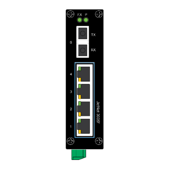
Page 15: Jetnet 3905F
See Front Panel LEDs on page 16 for further details System LED RJ-45 console ports Console/Terminal Port (RJ45) for device management/debug Fiber port 100BASE SC Type Fiber 3905f-s:Single-mode 30km 3905f-m:Multi-mode 2 km JetNet 3905 Series Installation Guide Page 15 of (35) -
Page 16: Front Panel Leds
Front Panel LEDs The system LEDs are used to monitor the switch activity and performance. The following illustration depicts the front panel on a JetNet 3905 Series. A specific LED panel is dependent on a specific JetNet model. Figure 3: Front Panel LEDs for JetNet 3905 Series No. -
Page 17: Rear View
JetNet 3905 Installation Guide 1.4. Rear View The following rear view illustrates the rear view of a JetNet 3905 Series device. For demonstration purposes a single sample is illustrated. Varying models may differ in shape and form. Figure 4: Rear Panel of JetNet 3905 Series No. -
Page 18: Bottom View
JetNet 3905 Installation Guide 1.5. Bottom View The following bottom view illustrates the bottom view of a JetNet 3905 Series device. The power inputs and relay connectors are located on the bottom panel of the switch as illustrated in the following illustrations. -
Page 19: Dimensions
1.6. Dimensions The power inputs and relay connectors are located on the rear panel of the switch as illustrated in the following illustrations. JetNet 3905 Figure 6: Dimensions of 5-Port JetNet 3905 JetNet 3905 Series Installation Guide Page 19 of (35) -
Page 20: Jetnet 3905F
JetNet 3905 Installation Guide JetNet 3905f Figure 7: Dimensions of 5-Port JetNet 3905f JetNet 3905 Series Installation Guide Page 20 of (35) -
Page 21: Electrical Safety Information
It may be difficult to ensure electromagnetic compatibility in other environments without appropriate precautions due to conducted and radiated disturbances. This equipment is provided as open-type equipment. Enclosures must be designed appropriately to JetNet 3905 Series Installation Guide Page 21 of (35) -
Page 22: Package Contents
2.3. Package Contents After unpacking the device, validate the contents to ensure you have received all the included components. • JetNet 3905 series includes a model: industrial Ethernet switch, model may include JetNet 3905, JetNet 3905f • Documentation — Quick Installation Guide 2.4. -
Page 23: Installing The Switch
In order to ensure the best performance of this equipment, it must be installed in a dust-free environment • It is important that the humidity around the switch does not exceed 90%. JetNet 3905 Series Installation Guide Page 23 of (35) -
Page 24: Din Rail Mounting
If the installation is accurate, the bottom part of the DIN rail should be fully inserted into the release tab. Figure 8: Installing the DIN-Rail Kit The following is an illustration of a completed DIN installation. JetNet 3905 Series Installation Guide Page 24 of (35) -
Page 25: Removing The Din-Rail Mounting Kit
Rotate the lower section of the device towards yourself and away from the DIN rail. When the bottom portion is no longer in contact with the DIN rail, lift the device directly upwards to detach it from the rail. JetNet 3905 Series Installation Guide Page 25 of (35) -
Page 26: Ethernet Cable Wiring
Pin 6 TD- → ← Pin 3 TD+ Pin 3 RD+ Pin 3 TD+ Pin 1 RD+ → → Pin 6 TD- Pin 6 RD- Pin 6 TD- Pin 2 RD- → → JetNet 3905 Series Installation Guide Page 26 of (35) - Page 27 1000Base-TX: 4-pair UTP/STP Cat. 5 cable, EIA/TIA-568 100-ohm (100m) • IEEE 802.3af: 4-pair UTP/STP Cat. 5 cable, EIA/TIA-568 100-ohm (100m) • IEEE 802.3at: 4-pair UTP/STP Cat. 5e / 6 cable, EIA/TIA-568 100-ohm (100m) JetNet 3905 Series Installation Guide Page 27 of (35)
-
Page 28: Data And Power Ports
Description RX + and V port - RX - and V port - TX + and V port + TX – and V port + 4, 5, 7, 8 Not applicable JetNet 3905 Series Installation Guide Page 28 of (35) -
Page 29: Connecting Power Inputs
To minimize network downtime caused by power loss, a redundant power configuration is supported by incorporating a secondary power supply unit. This enables the use of dual power inputs. Figure 12: Power Wiring Diagram JetNet 3905 Series Installation Guide Page 29 of (35) -
Page 30: Considerations
Make sure the device is properly grounded before connecting it. An improper grounding setup may pose a safety risk and could be hazardous. The ground connection must always be made first and disconnected last when installing or replacing the unit. JetNet 3905 Series Installation Guide Page 30 of (35) - Page 31 Install the lug and the wire assembly over the grounding hole and secure with the ground-lug screw (60 in-lb). Connecting the other end of the grounding wire to a grounding point. Figure 13: Installing a Ground Lug and Wire JetNet 3905 Series Installation Guide Page 31 of (35)
-
Page 32: Wiring A Relay
Avoid using any power components that are not explicitly designated for the switch device. To service or wire the switch, it is essential to power down the device and disconnect the power cord. JetNet 3905 Series Installation Guide Page 32 of (35) - Page 33 Ensure the terminal block is secure by pressing it firmly in the receptor. If necessary, tighten the screws on the terminal block. If there is no visible gap between the terminal block and the receptor, it indicates that the terminal block is correctly seated. JetNet 3905 Series Installation Guide Page 33 of (35)
-
Page 34: Disconnecting Power Inputs
Figure 16: Installing Power Cabling in a Terminal Block Ensure the terminal block is secure by pressing it firmly in the receptor. If necessary, tighten the screws on the terminal block. JetNet 3905 Series Installation Guide Page 34 of (35) -
Page 35: Power Supply Specifications
JetNet 3905 Installation Guide Power Supply Specifications Table 1 Power Supply Specifications - JetNet 3905 Series Model Input Range Power Consumption JetNet 3905 10-60 VDC JetNet 3905f JetNet 3905 Series Installation Guide Page 35 of (35)
Need help?
Do you have a question about the JetNet 3905 Series and is the answer not in the manual?
Questions and answers