
Subscribe to Our Youtube Channel
Summary of Contents for Kessler TSM
- Page 1 Assembly instructions with operating and maintenance information Torque motor Type: TSM,TMS TMU, TMI HTM, HTMx HTMe, STMx Art. no.: see type plate/data sheet Serial no.: see type plate/data sheet...
- Page 2 Assembly instructions Franz Kessler GmbH Franz-Kessler-Straße 2 88422 Bad Buchau, Germany Tel.: +49 (0)7582 809-0 Fax: +49 (0)7582 809-170 E-Mail: info@kessler-group.biz Web: http://www.kessler-group.biz Created: 24.04.2015 Issue: 09.06.2021 / bbe Assembly instructions: 000.624.690_EN Original Assembly Instructions - German All other languages are a translation of the original.
-
Page 3: Table Of Contents
Assembly instructions Contents About these assembly instructions ................ 7 1.1 Product designation ....................7 1.2 Importance of these assembly instructions ..........7 1.3 Scope of delivery ....................8 For your safety ....................... 9 2.1 Designated use ......................9 2.2 Non-authorised usage ..................9 2.3 Protection class IP54 ..................... - Page 4 Assembly instructions 5.1 Important notice ....................24 5.1.1 Environmental conditions ................24 5.1.2 Specific dangers .................... 24 5.2 Motor design ......................25 5.2.1 Stator ......................... 25 5.2.2 Rotor ........................25 5.2.3 Rotor shaft ....................... 26 5.2.4 Housing ......................26 5.3 Installation ....................... 27 5.3.1 Preparing for installation ................
- Page 5 12 Error report ........................62 13 Connections ......................... 63 14 EC declaration of conformity ................. 64 15 Service and support ....................65 15.1 KESSLER Germany ....................65 15.2 KESSLER USA ......................65 15.3 KESSLER China ..................... 66 15.4 KESSLER Taiwan ....................66 15.5 KESSLER Russia ....................
- Page 6 Assembly instructions Torque motor...
-
Page 7: About These Assembly Instructions
Assembly instructions 1 About these assembly instructions About these assembly instructions The copyright on these assembly instructions remains with Franz Kessler GmbH. They may not be copied, distributed or made accessible to others either in part or in full without permission. -
Page 8: Scope Of Delivery
Assembly instructions 1 About these assembly instructions Scope of delivery Torque motor Assembly instructions German Assembly instructions English Assembly instructions, additional languages in accordance with technical data sheet Torque motor 8/69... -
Page 9: For Your Safety
Assembly instructions 2 For your safety For your safety The unit is designed in such a way that it can be operated safely and with a high degree of reliability after correct installation of electrical power, coolant, cooling lubricant, hydraulic system, pneumatic system and sensor system as well as correct programming of the motor control. -
Page 10: Operator's Responsibility
Assembly instructions 2 For your safety Operator's responsibility Read these assembly instructions before assembly and commissioning, and follow the warning and safety instructions carefully. In addition to these assembly instructions, the instructions attached to the unit must also be observed. Knowledge of these assembly instructions is essential for avoiding accidents and ensuring fault-free operation. -
Page 11: Qualified Technical Staff
Assembly instructions 2 For your safety Qualified technical staff Work on the unit must be carried out strictly by qualified technical staff. The staff must have read and understood these assembly instructions. Qualified technical staff is staff who are familiar with the installation, assembly, commissioning and operation of the product. -
Page 12: Information About Warning Notices
Assembly instructions 2 For your safety Information about warning notices To emphasise safety relevant procedures in these assembly instructions the following warning notices apply. Warning notices consist of a signal word and a warning sign. If appropriate, prohibiting signs are used. 2.7.1 Warning symbols Following is a list of warning symbols used. -
Page 13: Damage To Property
Assembly instructions 2 For your safety 2.7.3 Damage to property Warns about possible damage to property. Failure to observe the notices can NOTICE result in damage to property. 2.7.4 Other symbols used Prohibiting signs denote a prohibited action, e.g. Entry prohibited. ... -
Page 14: Safety Instructions
Assembly instructions 2 For your safety Safety instructions Observe the following safety instructions in order to avoid danger to persons or the environment. 2.8.1 Danger due to electrical voltage Acute danger of injury or to life from electric shock! Electric shock can result in the following: Death, cardiac arrest, respiratory arrest, neural damage, burns and consequential injury such as broken bones. -
Page 15: Danger Due To Electromagnetic Fields
Assembly instructions 2 For your safety 2.8.2 Danger due to electromagnetic fields There is danger of injury or death due to electromagnetic fields in the vicinity of permanent magnets! An acute danger to the life of persons with pacemakers exists in the immediate vicinity of permanent magnets! Pacemakers are influenced by electromagnetic fields! In the immediate vicinity of permanent magnets there is an acute danger of... -
Page 16: Danger To The Environment From Operating Fluids
Assembly instructions 2 For your safety 2.8.4 Danger to the environment from operating fluids Danger to the environment from operating fluids! Operating fluids such as lubricating grease, hydraulic fluid, cooling agent, cleaning fluid etc. must not be allowed to enter the ground, the water supply or the sewer system. -
Page 17: Product Information
Assembly instructions 3 Product information Product information Product identification The unit can be identified by its type plate. The type plate is securely attached and may not be removed. In addition, the article number and/or serial number are engraved on the unit. Product designation Product name Torque motor... -
Page 18: Transport And Storage
Assembly instructions 4 Transport and storage Transport and storage Transport Transport may only be carried out by qualified technical staff or a specialised company. Read the safety information. See chapter "For your safety". The gross weight can be found in the chapter "Product information". Danger of injury or death due to electromagnetic fields in the vicinity of permanent magnets! DANGER! - Page 19 Assembly instructions 4 Transport and storage Risk of damage from corrosion NOTICE If the unit is unpacked too quickly or exposed to fluctuating temperatures, this could lead to corrosion and, as a consequence, damage to the unit. Store the unit for at least 24 hours at a temperature of 23 ±2°C. After this, first remove the protective foil.
-
Page 20: Transport With Lifting Eye Bolts
Assembly instructions 4 Transport and storage 4.1.4 Transport with lifting eye bolts The motor is provided with threads for lifting eye bolts. Only use the lifting eye bolts supplied to transport the unit. If lifting eye bolts are not included in the scope of delivery we recommend the use of Star Point VRS lifting eye bolts. -
Page 21: Storage
Assembly instructions 4 Transport and storage Storage Risk of damage from incorrect storage and return transport NOTICE Incorrect storage and return transport can result in corrosion or damage to the unit. Observe the following instructions for storage time, environmental conditions, corrosion and damage protection. -
Page 22: Protection From Damage
Assembly instructions 4 Transport and storage 4.2.4 Protection from damage The motor must be protected from vibration and oscillations. Store the motor on a base which isolates against vibration. Store motor and motor parts horizontally in the original packaging. Torque motor 22/69... -
Page 23: Storage Of Components With Permanent Magnets
Assembly instructions 4 Transport and storage 4.2.5 Storage of components with permanent magnets Danger of injury or death due to electromagnetic fields in the vicinity of permanent magnets! DANGER! Danger of injury or death for persons with pacemakers, metal implants or metal parts in the body. -
Page 24: Assembly
Assembly instructions 5 Assembly Assembly Important notice The assembly section contains important information on the connections and the specifications for the required media. Work on the unit must be carried out strictly by qualified technical staff. 5.1.1 Environmental conditions The environmental conditions influence functionality and service life of the unit. ... -
Page 25: Motor Design
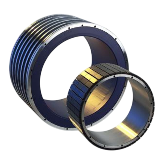
Assembly instructions 5 Assembly Motor design The motor is a synchronous motor. The motor consists of two main assemblies: • the stator assembly • the rotor assembly The measurements and tolerances can be found in the dimension sheet and/or data sheet. 5.2.1 Stator The stator assembly consists of the laminated stator with winding and the shrink-fit... -
Page 26: Rotor Shaft
Assembly instructions 5 Assembly 5.2.3 Rotor shaft The rotor shaft is manufactured in accordance with the specified measurements and tolerances of the relevant dimension sheet. Ensure that all edges of the rotor shaft are absolutely burr-free. 5.2.4 Housing The housing for the motor must be adapted to match the shape and dimensions of the stator cooling jacket (see dimension sheet). -
Page 27: Installation
Assembly instructions 5 Assembly Installation The unit was designed and built to the specifications of the customer. The fitting surfaces must comply with the specified measurements and tolerances. Fitting of the unit may only be carried out by qualified technical staff. ... - Page 28 Following is an installation example. If you have any questions, please contact our service department. • Contact details for the Kessler Service can be found in the chapter “Service and Support”. Installation steps (1) Wrap a 1 mm thick aluminium sheet around the rotor shaft. Ensure that the rotor bandage is not damaged.
-
Page 29: Electrical System
Assembly instructions 5 Assembly Electrical system Work on the electrical system may only be carried out strictly by an electrician. Before you begin work on the electrical system, read the safety instructions. See chapter “For your safety”. Ensure that a second qualified person is available to disconnect the power supply in the event of an emergency. - Page 30 Assembly instructions 5 Assembly For connection with plug The electrical interface consists of one or more plugs. The connector allocation can be found in the dimension sheet and/or circuit diagram. Ensure correct fit of plug connections. Ensure correct fitting of the O-rings in the connector. Leaking plug connections can lead to short-circuit and result in damage to the unit, the machine and the surrounding area.
-
Page 31: Thermal Motor Protection
Assembly instructions 5 Assembly Thermal motor protection The electric motors are supplied with integrated temperature sensors. PTC thermistors and bimetal temperature sensors provide thermal motor protection. To guarantee protection, especially with load during standstill, each motor phase is provided with one of the three in-series connected temperature sensors. Motor damage possible NOTICE Motor damage from thermal overload is possible. -
Page 32: Electrostatic Discharge
Assembly instructions 5 Assembly 5.5.2 Electrostatic discharge Damage to electronic components from electrostatic discharge possible NOTICE Electrostatic discharge can cause damage to electronic components. Measures to protect from electrostatic charge are necessary. Observe the following instructions: Ensure that electronic components do not come into contact with electrically insulating materials such as plastic parts or foil, or synthetic clothing. -
Page 33: Protective Measures For The Temperature Sensor
When the shut-down limit for the motor temperature is reached the motor must be switched off immediately. Should the parameter list no longer be available, a copy can be requested from Kessler Service. See chapter “Service and Support“ for contact details. 5.5.6 PT1000 sensor To monitoring the coil temperature of the motor, the unit is equipped with a platinum temperature sensor. -
Page 34: Kty 84-130/Pt 1000 Sensor
Assembly instructions 5 Assembly 5.5.7 KTY 84-130/PT 1000 sensor The KTY 84-130/PT 1000 sensor measures the motor coil temperature. The sensor is a temperature-sensitive component. When the temperature rises, the electrical resistance increases. The characteristic curve is almost linear within the measuring range. -
Page 35: Ptc Thermistor Temperature Sensor
Assembly instructions 5 Assembly 5.5.9 PTC thermistor temperature sensor The PTC thermistor temperature sensors are elements which have an erratically changing characteristic curve. The resistance rises steeply in the area of the nominal response temperature (see data sheet). Example PTC thermistor resistance PTC thermistor temperature PTC thermistor resistance R depending on the PTC thermistor temperature T... -
Page 36: Connection Example
Assembly instructions 5 Assembly 5.5.10 Connection example Thermal motor protection Thermal motor protection can be effected either by means of the triple bimetal sensors (grey-pink) or the triple PTC sensors (grey-blue). Measuring the coil temperature In addition, the coil temperature can also be measured by the KTY 84-130/ PT 1000 sensor. -
Page 37: Hydraulic System
Assembly instructions 5 Assembly Hydraulic system Work on the hydraulic system must be carried out strictly by qualified technical staff with special knowledge and experience with hydraulic systems. Before you begin work on the hydraulic system, read the safety instructions. See chapter “For your safety”. -
Page 38: Avoid Wear Of Hydraulic Components
Assembly instructions 5 Assembly 5.6.2 Avoid wear of hydraulic components Limit pressure peaks In principle, pressure peaks must not exceed 10 % of the maximum pressure. Example: 80bar nominal pressure, 120bar maximum pressure (take value from data sheet). Maximum permissible pressure peak during operation with nominal pressure is 92bar (80bar +10% of 120bar). -
Page 39: Cooling System
Assembly instructions 5 Assembly Cooling system Work on the cooling system must be carried out strictly by qualified technical staff with special knowledge and experience with hydraulic systems. Before you begin work on the cooling system, read the safety instructions. See chapter “For your safety”. -
Page 40: Connection Data
Assembly instructions 5 Assembly 5.7.2 Connection data Cooling IN Cooling OUT 5.7.3 Important specifications for the cooling agent Pure water severely lowers the pH-value and causes immediate corrosion to uncoated parts. The corrosion goes unnoticed for a time, but later can cause serious corrosion damage. -
Page 41: Protective Measures
If you use system cleaner, first make sure that the cooling system of the plant is rinsed through separately to remove any particles which are present. Only include the cooling system of the Kessler unit after you have done this. Torque motor... -
Page 42: Cooling System Settings
Assembly instructions 5 Assembly 5.7.6 Cooling system settings Optimum operating conditions Optimum operating conditions occur at the following temperatures: Optimum room temperature: 18 – 30 °C Optimum coolant temperature on entry to the motor: 20 - 25 °C Set the cooling unit so that the coolant temperature on entry to the motor lies in the optimum range between 20 °C and 25 °C. -
Page 43: Anti-Corrosion Agent
Assembly instructions 5 Assembly 5.7.7 Anti-corrosion agent If the unit is installed in a system, adhere to the specifications for the coolant in the assembly instructions of the system. When installing a closed water cooling circuit, add an anti-corrosion agent. Observe the manufacturer's instructions on the mixing ratio. -
Page 44: Cooling Diagram
Assembly instructions 5 Assembly 5.7.8 Cooling diagram H1: Cooling IN H2: Cooling OUT Torque motor 44/69... -
Page 45: Commissioning
Assembly instructions 6 Commissioning Commissioning Work on the unit must be carried out strictly by qualified technical staff. Before you begin commissioning, read the safety instructions. See chapter “For your safety”. Before commencing commissioning, ensure that all assembly and connection work is completed. -
Page 46: Limiting Maximum Current
Assembly instructions 6 Commissioning Electrical connections Acute danger of injury or to life from electric shock! Work on the electrical system may only be carried out by an electrician. DANGER! Ensure that the electrical connections are correctly carried out. ... -
Page 47: During Operation
Assembly instructions 7 During operation During operation Monitoring of media supply Recommendation for ensuring media supply To ensure service life and safe function and to reduce failure of the unit the specified values for media supply must be observed.. We recommend monitoring and, if necessary, control of the media supply. ... -
Page 48: Operation Of The Motor
Assembly instructions 7 During operation Operation of the motor Damage to the motor due to excessive voltage loads is possible NOTICE Observe the following instructions: Considerable voltage peaks can occur due to system oscillations when operating the motor with a frequency converter with pulsed voltage output (e.g. PWM). Significant influencing factors, along with the motor size, include the length of the connection leads as well as the number and type of axes in the drive assembly. - Page 49 Assembly instructions 7 During operation Max. torque for synchronous motors The maximum torque has been reached, when the motor has drawn the maximum permissible current. The maximum permissible current is limited by the demagnetisation danger of the rotor's permanent magnets. ...
-
Page 50: Oscillation Speeds Of The Motor
Assembly instructions 7 During operation Oscillation speeds of the motor The maximum permitted oscillation speed of the unit must not be exceeded during operation. If the maximum permitted oscillation speed is exceeded, this can result in damage to the motor. 7.5.1 Permitted oscillation speed while running idle The oscillation speed must be checked for the complete speed range of the motor. -
Page 51: Maintenance
Franz Kessler GmbH. • Contact details for the Kessler Service can be found in the chapter “Service and Support”. The Kessler Academy offers practical seminars for qualification of personnel. -
Page 52: Electrical System
Assembly instructions 8 Maintenance Electrical system Work on the electrical system may only be carried out strictly by an electrician. Before you begin work on the electrical system, read the safety instructions. See chapter “For your safety”. Ensure that a second qualified person is available to disconnect the power supply in the event of an emergency. -
Page 53: Cooling System
Assembly instructions 8 Maintenance Cooling system Work on the cooling system must be carried out strictly by qualified technical staff with special knowledge and experience with hydraulic systems. Before you begin work on the cooling system, read the safety instructions. See chapter “For your safety”. - Page 54 Assembly instructions 8 Maintenance Weekly Check pressure Check that the cooling unit is supplying sufficient operating pressure. Observe pressure specifications. See data sheet. Check the cooling agent level Observe the plant manufacturer's or operator's instructions. Monthly Check flow ...
- Page 55 Assembly instructions 8 Maintenance Immediately when defective, otherwise after 2 years Replace hose lines Due to the fact that hoses for coolant are subject to aging processes, their shelf and usage life is limited. We recommend replacing hoses after a usage life of a maximum of two years. ...
-
Page 56: Repairs
Franz Kessler GmbH. • Contact details for the Kessler Service can be found in the chapter “Service and Support”. The Kessler Academy offers practical seminars for qualification of personnel. -
Page 57: Decommissioning
Assembly instructions 10 Decommissioning 10 Decommissioning Decommissioning may only be carried out by qualified technical staff. Before you begin decommissioning, read the safety instructions. See chapter “For your safety”. Acute danger of injury or to life from electric shock! Failure to observe the warning notices and safety instructions can result in DANGER! electric shock. -
Page 58: Sequence For Decommissioning
Assembly instructions 10 Decommissioning 10.1 Sequence for decommissioning Observe the sequence for decommissioning. Decommissioning the unit (1) Stop the unit. (2) Wait until the voltage in the controller has dissipated (approx. 10 minutes). (3) Check that the unit is free of voltage. Electrical system Before the unit can be dismantled the electrical connections and the system must be put out of operation. -
Page 59: Disassembly
Only work on the unit when it has cooled down and is switched off. Wear protective gloves when working. 10.3 Disposal Dispose of the unit in accordance with applicable local legal regulations. You can also return worn-out units to the Franz-Kessler GmbH. We will carry out appropriate disposal. Torque motor 59/69... -
Page 60: Fault Correction
Before you begin with fault correction, read the safety instructions. See chapter “For your safety”. If you cannot eliminate the fault, request a Kessler technician. • Contact details for the Kessler Service can be found in the chapter “Service and Support”. 11.1 Fault diagnosis 11.1.1... - Page 61 Assembly instructions 11 Fault correction Motor gets too hot: Motor parameters set incorrectly. Check motor parameters and set them Other causes. correctly. See parameter list. Stator coil too hot due to continual load Check if rated output is exceeded. If operation.
-
Page 62: Error Report
Assembly instructions 12 Error report 12 Error report In the event of an error on the unit, please fax this checklist completed in full to Franz Kessler GmbH, Deutschland. Fax: +49 (0)7582 809-172 Customer details Company Telephone Street Postcode/town Date... -
Page 63: Connections
Assembly instructions 13 Connections 13 Connections Further information on connections can be found in the dimension sheet. Designation Temperature sensor Power connection Cooling IN Cooling OUT Connection example Torque motor 63/69... -
Page 64: Ec Declaration Of Conformity
14 EC declaration of conformity 14 EC declaration of conformity pursuant to the Low Voltage Directive 2014/35/EU We the manufacturer: • Franz Kessler GmbH, 88422 Bad Buchau, Germany hereby declare that the following product: Torque motor Type: TSM,TMS TMU, TMI... -
Page 65: Service And Support
Fax: +49 (0)7582 809-172 e-mail: service@kessler-group.biz Sales Tel.: +49 (0)7582 809-0 Fax: +49 (0)7582 809-170 e-mail: sales@kessler-group.biz Kessler Academy (Seminars & Training) Tel.: +49 (0)7582 809-4003 Fax: +49 (0)7582 809-170 e-mail: akademie@kessler-group.biz 15.2 KESSLER USA KESSLER USA Inc. 44099 Plymouth Oaks Blvd. -
Page 66: Kessler China
Assembly instructions 15 Service and support 15.3 KESSLER China KESSLER (Shanghai) Spindle Service Co. Rm. 201, Building #16 No. 318 Yuanshan Rd. Minhang District 201108 Shanghai Tel.: +86 (21) 6489-7034 Fax: +86 (21) 6489-7134 e-mail: info.cn@kessler-group.biz 15.4 KESSLER Taiwan KESSLER TAIWAN Co. Ltd. -
Page 67: Revision Index
Assembly instructions 16 Revision index 16 Revision index Index Date Change 10.05.2012 KTY-84-130 changed 20.06.2012 Storage and return transport (corrosion protection) 25.09.2013 Contents updated 10.06.2015 Contents updated 18.04.2017 Contents updated 19.06.2018 Contents updated (PT1000) 27.05.2019 Contents updated (PT1000) 09.06.2021 Contents updated Torque motor 67/69... -
Page 68: Index
Commissioning ................45 Preparation ................. 45 Connection list ................63 Installation..................27 Contact details ................. 7 Example ..................28 Kessler Academy ..............65 Installation position ............... 9 Sales ....................65 Service ..................65 Coolant specifications/quality ............. 40 Coolant temperature ..............42 KESSLER China ................ - Page 69 Assembly instructions 17 Index Protective equipment, minimum requirements ....11 Temperature sensor PT1000 ..................33 Transport ..................18 Qualified technical staff .............. 11 Transport with lifting eye bolts ..........20 Tubing Diameter ..................39 Type of construction ..............9 Repairs ....................56 unit ......................
Need help?
Do you have a question about the TSM and is the answer not in the manual?
Questions and answers