Advertisement
Quick Links
BY
CDHD
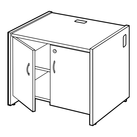
CDHD39
DOOR UNIT
IM P O RTA N T !
Assembly may require the assistance of
another person.
Before you begin assembly:
READ THE DIRECTIONS all the way through one
time. This will speed up the process and help you
understand the sequence of steps.
COUNT THE PARTS AND HARDWARE before
assembly. This ensures you have received all
necessary parts before you begin.
TOOLS: You may need a Phillips head screwdriver,
a medium slotted screwdriver or a plastic mallet. To
protect your new furniture from damage during
assembly, it is recommended to work on a carpeted
surface.
0920
In the event any parts are missing from
this package, send your name, address,
telephone number, and a description of
the missing part(s) to: PARTS, Box 1420,
Missoula, MT 59806 or call:
1-800-769-5693 or FAX 1-800-445-5281.
CAUTION: On assemblies requiring glue, make
sure the unit is assembled correctly before gluing.
Once this unit is assembled with glue, the
manufacturer will not be responsible for damaged
parts. Keep a damp cloth or sponge handy to wipe
off excess glue.
To care for this furniture, simply wipe with a cloth
dampened with glass cleaner containing ammonia-D.
Advertisement

Related Manuals for Ironwood GLACIER CDHD


Summary of Contents for Ironwood GLACIER CDHD
- Page 1 CDHD CDHD39 DOOR UNIT IM P O RTA N T ! In the event any parts are missing from Assembly may require the assistance of this package, send your name, address, another person. telephone number, and a description of Before you begin assembly: the missing part(s) to: PARTS, Box 1420, Missoula, MT 59806 or call: READ THE DIRECTIONS all the way through one...
-
Page 2: Parts Diagram
PARTS DIAGRAM Right Side - CDHD 01010341 1 ea. Left Side - CDHD 01010341 1 ea. Right Side - CDHD39 01010443 1 ea. Left Side - CDHD39 01010443 1 ea. 01010301 1 ea. Back - CDHD 01010152 1 ea. Back - CDHD39 01010252 1 ea. - Page 3 HARDWARE Leveler Insert 274650 4 ea. Leveler H2002 4 ea. Flush Rafix Cam 909911 6 ea. Hinge Plate 400207 4 ea. #8 x 5/8" 988056 4 ea. Catch Plate 452340 1 ea. Panhead Screw Varianta Screw 988060 8 ea. Angle Bracket 401170 2 ea.
- Page 4 #6 x 5/8" 901216 2 ea. Panhead Screw 452310 452320 1 ea. Lock & Key Set 452350 1" Washerhead 920200 4 ea. Screw Handle 400870 2 ea. Door Bumper 298030 2 ea. Door Plate 452330 1 ea. Rafix Shelf 909912 6 ea.
- Page 5 Using the Rafix System: Insert the Rafix Cams into the appropriate holes. The flat edge of the cam should be facing the edge Flat of the panel. edges must be Slide Rafix Cams of the panel to be aligned attached onto the corresponding posts. When screwing post into hole, Do Not over tighten.
- Page 6 Place the Left Side (A) and Right Side (B) on a clean, carpeted surface with the pre-drilled holes facing up. Insert the Leveler Inserts (H1) into the holes in the bottom edges of each Side. Using a plastic mallet, tap until flush with the surface. Screw the Levelers (H2) into the Leveler Inserts. Adjust Levelers when the assembled unit is in place.
- Page 7 Insert six rafix Cams (H10) into the Top (C) with the arrows of the cams facing out. Attach a Catch Plate (H5) to the Top as shown using two #8 x 5/8" Panhead Screws (H6). Insert six Flush Rafix Cams (H4) into the Back (D) and six Rafix Cams (H10) into the Bottom (E) with the...
- Page 8 Attach the Toeboard (F) to the Bottom (E) using three Confirmat Screws (H9) through the pre-drilled holes as shown. NOTE: The Angle Brackets should be oriented towards the inside as shown. Place the Left Side (A) as shown. Position the Top (C) onto the Left Side.
- Page 9 # 10 Position the Bottom Shelf (E) and Toeboard (F) assembly onto the Left Side (A) # 11 Position the bolts and dowels of the Right Side (B) onto the units cams (H4) and (H10)
- Page 10 Secure the Angle Brackets (H7) of the Toeboard (F) to the Left Side (A) and Right Side (B) using Varianta Screws (H8). Insert six Rafix shelf cams (H20) into the Adjustable Shelf (G) with the flat edge facing outwards # 13 and tap until fully seated in place as shown.
- Page 11 # 15 Position the Adjustable Shelf (G) onto the posts as shown. # 16 Press Hinges (H12) into the corresponding holes in the Left Door (L) and Right Door (M). Tap into place. Tighten the screws of each Hinge to secure in place.
- Page 12 # 17 Position the Lock (H13) onto the inner side of the Right Door (M) oriented as shown. Secure the Lock in place using two #6 x 5/8" Panhead Screws (H14) into the pre-drilled holes of the Right Door. Press the trim ring of the lock over the keyhole portion of the lock on the opposite side of Right Door as shown.
- Page 13 # 20 To attach the Left Door (L) to the unit, slide the Door Hinges (H12) onto the Hinge Plates (H3) as shown. Tighten the center screw. # 21 To attach the Right Door (M) to the unit, slide the Door Hinges (H12) onto the Hinge Plates (H3) as shown.
- Page 14 Step B. Loosen the center screw of the hinge plate for IN and OUT door adjustment. Retighten center screw after proper adjustment is made. Step C. To adjust the gap between the doors, turn this screw. For a smaller gap, turn the screw clockwise.
- Page 15 # 24 Insert Grommets (H19) into the Left Side (A), Right Side (B), Top (C), Bottom (E) and the Adjustable Shelf (G). Your Glacier Hinged Door unit is now fully assembled and ready for use. CONNECTING TO OTHER CIRCULATION DESK UNITS Align the side panels of the units to be Remove Grommets from the panels to be connected.
Need help?
Do you have a question about the GLACIER CDHD and is the answer not in the manual?
Questions and answers