Advertisement
Quick Links
BY
CDTD
CDTD39
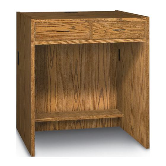
TWO DRAWER
IM P O RTA N T !
Assembly may require the assistance of
another person.
Before you begin assembly:
READ THE DIRECTIONS all the way through one
time. This will speed up the process and help you
understand the sequence of steps.
COUNT THE PARTS AND HARDWARE before
assembly. This ensures you have received all
necessary parts before you begin.
TOOLS: You may need a Phillips head screwdriver,
a medium slotted screwdriver or a plastic mallet. To
protect your new furniture from damage during
assembly, it is recommended to work on a carpeted
surface.
0920
UNIT
In the event any parts are missing from
this package, send your name, address,
telephone number, and a description of
the missing part(s) to: PARTS, Box 1420,
Missoula, MT 59806 or call:
1-800-769-5693 or FAX 1-800-445-5281.
CAUTION: On assemblies requiring glue, make
sure the unit is assembled correctly before gluing.
Once this unit is assembled with glue, the
manufacturer will not be responsible for damaged
parts. Keep a damp cloth or sponge handy to wipe
off excess glue.
To care for this furniture, simply wipe with a cloth
dampened with glass cleaner containing ammonia-D.
Advertisement

Subscribe to Our Youtube Channel
Related Manuals for Ironwood GLACIER CDTD


Summary of Contents for Ironwood GLACIER CDTD
- Page 1 CDTD CDTD39 TWO DRAWER UNIT IM P O RTA N T ! In the event any parts are missing from Assembly may require the assistance of this package, send your name, address, another person. telephone number, and a description of Before you begin assembly: the missing part(s) to: PARTS, Box 1420, Missoula, MT 59806 or call:...
-
Page 2: Parts Diagram
PARTS DIAGRAM 01010541 1 ea. 01010541 1 ea. Left Side - CDTD Right Side - CDTD Left Side - CDTD39 0101641 1 ea. Right Side - CDTD39 01010641 1 ea. 01010501 1 ea. 01010152 1 ea. Back - CDTD Back - CDTD39 01010252 1 ea. - Page 3 Drawer End 1069470 4 ea. Drawer Bottom 1191665 2 ea. Drawer Side 1069870 4 ea. HARDWARE Leveler Insert 274650 4 ea. Leveler 300870 4 ea. Rafix Cam 909909 12 ea. Rafix Bolt 909925 22 ea. Flush Rafix Cam 909910 10 ea. Varianta Screw 988060 8 ea.
- Page 4 LOCKSET 170-HP #6 x 5/8" 901120 4 ea. Flathead Screw 452310 Cam Lock 2 ea. 452360 Bezel 452350 2 ea. Drawer Handle 400870 2 ea. 902215 4 ea. 1 3/4" Screw #6 x 3/8" 01115 12 ea. Panhead Screw Glue 295020 1 ea.
- Page 5 Using the Rafix System: Insert the Rafix Cams into the appropriate holes. The flat edge of the cam should be facing the edge Flat of the panel. edges must be Slide Rafix Cams of the panel to be aligned attached onto the corresponding posts. When screwing post into hole, Do Not over tighten.
- Page 6 Screw nine Rafix Bolts (H3) into the Left Side Panels (A & B) where indicated. Attach a Full Extension Slide (S1) to Left Side (A) using two Varianta Screws (H5) as shown. Note: It will be necessary to slide the sliding portion forward to access the 1st hole.
- Page 7 Attach a Full Extension Slide (S1) to the right side of the Divider (J) using two Varianta Screws (H5) as shown. Attach a Full Extension Slide (S1) to the left side of the Divider (J) using two Varianta Screws (H5) as shown. Insert six Rafix Cams (H4) into the Top (C) with the arrows of the cams facing out.
- Page 8 Screw two Rafix Bolts (H3) into the Top (C) where indicated. Insert Rafix Flush Cams (H6) into the Divider (J) with the arrows of the cams facing out. # 10 Position the Divider (J) onto Be sure slides the Top (C) and turn the cams extend to the clockwise to secure.
- Page 9 # 11 Insert Flush Rafix Cams (H6) into the back (D) and Rafix Cams (H4) into the shelf (D) where indicated # 12 Secure an Angle Bracket (H9) to each end of the Toeboard (F) using the Panhead Screws (H10). # 13 Insert two Rafix Cams (H4) into the Bottom (E) with the...
- Page 10 # 14 Attach the Toeboard (F) to the Bottom (E) using three Confirmat Screws (H11) through the pre-drilled holes as shown. Note: The Angle Brackets should be oriented towards the inside as shown. # 15 # 16 Position the Top (C) and Divider (J) Position the Back (D) onto the Left Side assembly onto the Left Side (A).
- Page 11 # 17 Position the Top Shelf (G) onto the Left Side (A) and attach Top Shelf (G) to Divider (J) by turning cams Position the Toeboard and Bottom Position the bolts and dowels of the # 18 # 19 assembly (F & E) onto the Left Side (A) Right Side (B) onto the unit and turn and turn the cam (H4) to secure.
- Page 12 # 20 Secure the Angle Brackets (H9) of the Toeboard (F) to the Left Side (A) and Right Side (B) using #14x1/2" Panhead Screws (H10). # 21 Apply glue (H19) to the edges of the Drawer Ends as shown. Use four Confirmat Screws (H11) to attach Drawer Side (D1) to Drawer Ends (D2) with the grooves aligned on the...
- Page 13 # 23 # 24 Apply glue (H19) to the exposed edge of Attach the Drawer Front (L) to the Drawer the Drawer Bottom (D5) and the Drawer assembly using two Washerhead Screws Ends (D2). Position the other Drawer Side (H12). (D1) onto unit with the groove aligned with the edge of the bottom.
- Page 14 # 27 Attach a Drawer Handle (H6) to the Drawer Front (L) as shown using two 1-3/4" Screws (H17). # 28 You must disassemble the the Full Extension Slide before proceeding to the next step. The Full Extension Slides (S1) consist of the main slide sections and the channel sections. The four slides were installed on Sides A and B and on both sides of the Divider (J).
- Page 15 # 30 Attach a channel portion of the Full Extension Slide (S1) to the right side of both drawer assemblies using #6x3/8" Panhead Screws (H18) as shown. RIGHT SIDE CHANNEL # 31 Assemble the second Drawer unit in the same manner. Extend cabinet portions of the Full Extension slides completely out.
- Page 16 CONNECTING TO OTHER CIRCULATION DESK UNITS Remove Grommets from the panels to be connected. Using a 13/64" bit, drill through the four pilot holes on the inside of each side panel. Align the side panels of the units to be connected. Tap four Connector Sleeves (H21) through the holes in one side panel and into the holes of the unit to be connected.
Need help?
Do you have a question about the GLACIER CDTD and is the answer not in the manual?
Questions and answers