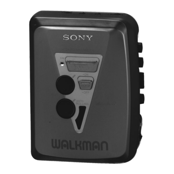
Sony WM-EX372 Service Manual
Hide thumbs
Also See for WM-EX372:
- Operating instructions (2 pages) ,
- Operating instructions (2 pages) ,
- Service manual (18 pages)
Advertisement
Quick Links
SERVICE MANUAL
Ver 1.2 1999. 03
With SUPPLEMENT 1
(9-923-319-81)
With SUPPLEMENT 2
(9-923-319-82)
Dolby noise reduction manufactured under license
from Dolby Laboratories Licensing Corporation.
"DOLBY" and the double-D symbol a are trade-
marks of Dolby Laboratories Licensing Corporation.
MICROFILM
WM-EX372
Model Name Using Similar Mechanism
Tape Transport Mechanism Type
SPECIFICATIONS
AEP Model
E Model
TC-K6/K7
NEW
MT-WMEX372-114
CASSETTE PLAYER
Advertisement

Subscribe to Our Youtube Channel
Summary of Contents for Sony WM-EX372
- Page 1 WM-EX372 SERVICE MANUAL AEP Model E Model Ver 1.2 1999. 03 TC-K6/K7 With SUPPLEMENT 1 (9-923-319-81) With SUPPLEMENT 2 (9-923-319-82) Dolby noise reduction manufactured under license Model Name Using Similar Mechanism from Dolby Laboratories Licensing Corporation. Tape Transport Mechanism Type MT-WMEX372-114 “DOLBY”...
-
Page 2: Table Of Contents
TABLE OF CONTENTS Flexible Circuit Board Repairing • Keep the temperature of the soldering iron around 270 ˚C dur- ing repairing. GENERAL ..............3 • Do not touch the soldering iron on the same conductor of the circuit board (within 3 times). DISASSEMBLY ............ -
Page 3: General
SECTION 1 This section is extracted from instruction manual. GENERAL – 3 –... -
Page 4: Disassembly
SECTION 2 DISASSEMBLY • This set can be disassembled in the order shown below. CABINET (REAR) ASS’Y MAIN BOARD MECHANISM DECK BELT MOTOR (MT-WMEX372-114) (M901) MAGNETIC HEAD (HP901) MEGA BASS UNIT (DOLBY) CASSETTE HOLDER ASS’Y Note: Follow the disassembly procedure in the numerical order given. CABINET (REAR) ASS’Y 2 Insert the precision screw driver (1.4 mm flat-blade) in to the slit at claw A and release the claw. - Page 5 MAIN BOARD, MECHANISM DECK (MT-WMEX372-114) 2 flexible board (CN302) 6 main board 4 toothed lock (WH) screw (M1.4) 3 head flexible board (CN301) 1 Remove four solders of 8 Remove the mechanism motor lead (M901). deck (MT-WMEX372-114) to direction of the arrow. 5 two claws 7 claw 7 claw...
- Page 6 CASSETTE HOLDER ASS’Y 2 Insert a precision screwdriver (1.4 mm flat-blade) vertically in to portion A to release the hinge plate. 1 flexible board (CN302) 3 portion B to release the hinge plate. 5 spring (torsion) 4 cassette holder ass’y NOTE FOR INSTALLATION Note: Follow the assembly procedure in the numerical order given.
- Page 7 MEGA BASS UNIT (DOLBY) 1 two knobs (rotary) 5 flexible board three claws claw claw 3 Remove five claws as 2 claw move the mega bass unit (dolby) to direction of the arrow A . 4 mega bass unit (dolby) –...
-
Page 8: Mechanical Adjustments
SECTION 4 SECTION 3 MECHANICAL ADJUSTMENTS ELECTRICAL ADJUSTMENTS 3-1. MECHANICAL ADJUSTMENTS Precaution • Supplied voltage: 2.5 V Precaution • Switch and control position 1. Clean the following parts with a denatured-alcohol-moistened swab: NORM CrO /METAL switch: NORM playback head pinch roller VOLUME CONTROL: maximum capstan rubber belt... -
Page 11: 5-3. Schematic Diagram
WM-EX372 Ver 1.2 1999. 03 5-3. SCHEMATIC DIAGRAM • See page 15 for IC Block Diagrams. • Waveforms Note on Schematic Diagram: • All capacitors are in µF unless otherwise noted. pF: µµF 50 WV or less are not indicated except for electrolytics 2 IC601 !¡... -
Page 12: Exploded Views
WM-EX372 SECTION 6 EXPLODED VIEWS • IC Block Diagrams NOTE: IC331 NJM2185AV-TE2 • -XX and -X mean standardized parts, so they • Items marked “*” are not stocked since they are seldom required for routine service. Some may have some difference from the original one. - Page 13 (2) CABINET SECTION MT-WMEX372-114 Ref. No. Part No. Description Remark Ref. No. Part No. Description Remark 3-015-285-01 SCREW (M1.4), TOOTHED LOCK (WH) 3-932-037-01 SPRING (CASSETTE) A-3021-042-A MAIN BOARD, COMPLETE (EXCEPT French) 3-019-851-01 CABINET (FRONT) A-3021-043-A MAIN BOARD, COMPLETE (French) 3-022-581-01 PLATE, LIGHT GUIDE 3-022-698-01 TERMINAL (–), BATTERY 3-019-864-01 CABINET (REAR) 3-019-862-01 TERMINAL (+), BATTERY...
- Page 14 (3) MECHANISM DECK SECTION (MT-WMEX372-114) not suplied not suplied M901 HP901 Ref. No. Part No. Description Remark Ref. No. Part No. Description Remark X-3369-749-1 PINCH LEVER (N) ASSY 3-920-990-01 SPRING (UD), COMPRESSION 3-920-996-01 SPRING (PINCH N) 3-921-335-01 WASHER, LEVER X-3369-747-1 WHEEL ASSY, CAPSTAN 3-923-530-01 SLEEVE (M) 3-704-197-71 SCREW (M1.4) 3-728-091-01 WASHER, STOPPER...
-
Page 15: Electrical Parts List
SECTION 7 MAIN ELECTRICAL PARTS LIST NOTE: • Due to standardization, replacements in the • Items marked “*” are not stocked since they When indicating parts by reference number, please include the board. parts list may be different from the parts speci- are seldom required for routine service. - Page 16 WM-EX372 Ver 1.2 1999. 03 MAIN Ref. No. Part No. Description Remark Ref. No. Part No. Description Remark JR302 1-216-296-00 SHORT (CHIP) 0 R324 1-216-298-00 METAL CHIP 1/10W R331 1-216-001-00 METAL CHIP 1/10W JR303 1-216-296-00 SHORT (CHIP) 0 R332 1-216-081-00 METAL CHIP...
- Page 17 Addition of Chinese Model Chinese Model have been added. This is the same as E model which is not described in this supplement-1 Refer to WM-EX372 original service manual (9-923-319-11) for other information. ACCESSORIES & PACKING MATERIAL Page E model Chinese model Ref.
- Page 18 Addition of Tourist Model Tourist Model have been added. This is the same as E model which is not described in this supplement-2 Refer to WM-EX372 original service manual (9-923-319-∏) for other information. ACCESSORIES & PACKING MATERIAL Page E model Tourist model Ref.


Need help?
Do you have a question about the WM-EX372 and is the answer not in the manual?
Questions and answers