
Related Manuals for Panasonic SB-WAK640P


Summary of Contents for Panasonic SB-WAK640P
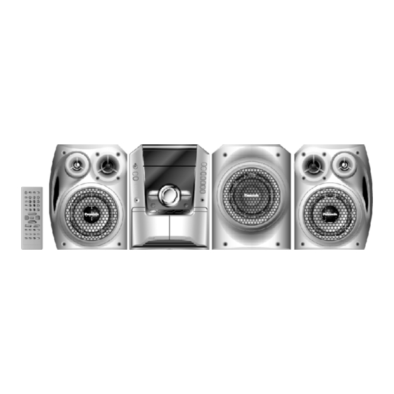
- Page 1 ORDER NO. MD0512449C1 Speaker System SB-WAK640P Colour (S)... Silver Type SPECIFICATIONS Specification PDF created with pdfFactory Pro trial version www.pdffactory.com...
-
Page 2: Assembling And Disassembling
3. The labels “HIGH” and “LOW” on the rear of the speakers refer to High frequency and Low frequency. Music Center : SA-AK640P-S System : SC-AK640P-S Front Speaker : SB-AK640P-S Subwoofer : SB-WAK640P-S Music Center : SA-AK640PC-S System : SC-AK640PC-S Front Speaker : SB-AK640P-S Subwoofer : SB-WAK640P-S 2005 Matsushita Electric Industrial Co. - Page 3 1. This section describes procedures for checking the operation of the major printed circuit boards and replacing the main components. 2. For reassembly after operation checks or replacement, reverse the respective procedures. Special reassembly procedures are described only when required. 3.
- Page 4 Step 1: Remove 4 screws from Front Panel Assembly. Step 2: Remove Front Panel Assembly from Speaker Cabinet Assembly as arrow shown. 1.3. Disassembly of Woofer Follow (step 1) to (step 2) in item 1.2. PDF created with pdfFactory Pro trial version www.pdffactory.com...
- Page 5 Step 1: Detach the (+) Red and (-) Black wires from Woofer. Step 2: Remove 4 screws from Woofer. 1.4. Disassembly of Speaker Cabinet Assembly Follow (step 1) to (step 2) in item 1.2. Follow (step 1) in item 1.3. PDF created with pdfFactory Pro trial version www.pdffactory.com...
-
Page 6: Connection Of The Speaker Cables
2. Connection of the Speaker Cables - Be sure to connect speaker cables before connecting the AC power supply cord. - The load impedance of any speaker used with this unit must be 8 - Be sure to connect the cable from the right speaker to the right terminal and the cable from the left speaker to the left terminal. - Page 7 Connection Use only the supplied speakers The combination of the main unit and speakers provide the best sound. Using other speakers can damage the unit and sound quality will be negatively affected. Note - Keep your speakers at least 10 mm (13/32”) away from the system for proper ventilation.
-
Page 8: Exploded View
3. Connection of the Wiring Diagram 4. Exploded view 4.1. Cabinet Parts Location 4.2. Packaging PDF created with pdfFactory Pro trial version www.pdffactory.com... -
Page 9: Replacement Parts List
5. Replacement Parts List Notes : - Important safety notice : When replacing any of these components, be sure to use only manufacturer’s specified parts shown in the parts list. - [M] markings in the Remarks columns indicates parts supplied by PAVCSG. - Page 10 Ref. No. Part No. Part Name & Description Remarks CABINET AND CHASSIS RYBX0127-S FRONT PANEL ASS’Y RYKX0313-S SPEAKER CAB. ASS’Y RKA0072-KJ LEG CUSHION RGNX0317-K SPEC SHEET XTB4+16AFJK SCREW XTB4+10GFJ SCREW PACKING MATERIALS RPNX0351 POLYFOAM SET RPFX0183 MIRAMAT SPEAKER L0AA16A00029 WOOFER FLE0512W/S PDF created with pdfFactory Pro trial version www.pdffactory.com...
Need help?
Do you have a question about the SB-WAK640P and is the answer not in the manual?
Questions and answers