
Subscribe to Our Youtube Channel
Related Manuals for Leister FUSION 1


Summary of Contents for Leister FUSION 1
- Page 1 FUSION 1 Leister Technologies AG Galileo-Strasse 10 CH-6056 Kaegiswil/Switzerland Tel. +41 41 662 74 74 +41 41 662 74 16 www.leister.com sales@leister.com...
- Page 2 English Operating Instructions...
-
Page 3: Table Of Contents
6.2 Working display ..........................11 7. Setup menu ............................13 7.1 Fixing the setpoint temperature setting .....................14 7.2 Switching off the air supply ......................14 8. Quick Reference Guide FUSION 1 ......................15 8.1 Switching on/Starting ........................15 8.2 Switching off ..........................15 9. Warnings and error messages ........................15 9.1 LCD display for warnings and error messages ...................15... -
Page 4: Important Safety Instructions
Operating instructions (translation of original operating instructions) Congratulations on your purchase of the FUSION 1. You have chosen a first-class hot-air extrusion welder. It has been developed and produced in accordance with the very latest standards of technology in the plas- tics-processing industry. -
Page 5: Intended Use
1.1 Intended use The FUSION 1 is designed for professional welding of thermoplastic materials made from PE and PP in the fields • container construction • pipeline construction • apparatus construction • landfill and contaminated sites • repairs Use only original Leister spare parts and accessories; otherwise, any warranty or guarantee claims will be invali- dated. -
Page 6: Transport
4. Your FUSION 1 4.1 Type plate and identification The model designation and serial number are indicated on the type plate (5) of your FUSION 1. Please enter this information in your operating instructions and always reference it when addressing inquiries to our representatives or authorized Leister Service Centers. -
Page 7: Overview Of Device Parts
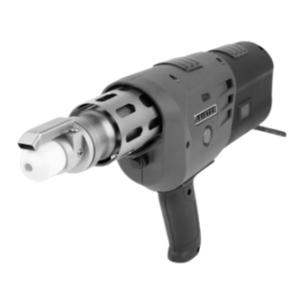
4.3 Overview of device parts 1. Drive motor/blower air inlet 9. Hot-air protective pipe 2. Welding rod openings 10. Air temperature potentiometer 3. Output regulation potentiometer 11. LCD display 4. Handle (can be mounted) 12. Hot-air blower switch 5. Type plate with model designation and series 13. -
Page 8: Preparation For Welding
5. Preparation for welding • Mount the handle (4) on the FUSION 1 (using locking nut 13) if required. Observe the maximum tightening torque of 4 Nm. • Prior to commissioning, check the power cord (6), the plug, and the extension cable for electrical and me- chanical damage. -
Page 9: Starting The Welding Process
• Point the prewarming nozzle (17) at the area to be welded. • Prewarm the area to be welded with oscillating movements. • Place the FUSION 1 on the prepared area to be welded and press the on/off drive switch (15). • Create and analyze a sample weld. -
Page 10: Checking The Temperature Of The Extrudate And The Prewarming Air
Risk of burning Always work with temperature-resistant gloves. Switch off the FUSION 1 while it is warm and disconnect it from the electrical line supply. • Removal – Remove the welding shoe (8) with the welding shoe holder (20) by detaching the clamping screws (18) from the extruder nozzle (22). -
Page 11: Lcd Display
Setpoint setting locked Line voltage is present, FUSION 1 is switched off 6.2 Working display As soon as the FUSION 1 is connected to the line voltage specified on the type plate (5), the current software version appears on the LCD display (11) for approximately 2 seconds. - Page 12 The potentiometer (3) can now be used Operating readiness to adjust the output regulation. The FUSION 1 is and output regula- ready for extrusion. tion adjustment...
-
Page 13: Setup Menu
7. Setup menu Drive button on °C/°F switching > 2 s Drive button on Drive button off > 1 s Temperature setting Drive button on locking > 2 s Drive button on Drive button off < 1 s Save settings Drive button on <... -
Page 14: Fixing The Setpoint Temperature Setting
7.1 Fixing the setpoint temperature setting The FUSION 1 provides the option of fixing the setpoint temperature setting. This prevents the required tempera- ture from being changed. This function is deactivated in the device’s as-delivered state. Setting the required Use the air temperature potentiometer (10) to setpoint set the required temperature. -
Page 15: Quick Reference Guide Fusion 1
After a drive motor overload, you must reset the electronics in order to continue working. To do this, you must disconnect the FUSION 1 from the power by pulling out the power plug. 9.1 LCD display for warnings and error messages... -
Page 16: Led Light Displays For Warnings And Error Messages
Drive overload, switch off FUSION 1, disconnect power plug, and allow FUSION 1 to cool down. Try again with a higher Error prewarming temperature. If the error keeps occurring, contact the Service Center. The drive for output regulation is not reaching the setpoint Warning speed. -
Page 17: Led Light Displays For Warnings And Error Messages
The carbon brushes of the blower are used up after approx. 550 operating hours and must then be replaced at your Leister Service Center. To protect the heating element, the heater is no longer activated if the carbon minimum length is undercut. -
Page 18: Training
Repairs must only be carried out by authorized Leister Service Centers. Leister Service Centers guarantee a professional and reliable repair service within 24 hours with original spare parts in accordance with circuit diagrams and spare parts lists. You will find the address of your authorized Service Center on the last page of these operating instructions. - Page 20 © Copyright by Leister Your authorised Service Centre is: Leister Technologies AG Galileo-Strasse 10 CH-6056 Kaegiswil/Switzerland Tel. +41 41 662 74 74 +41 41 662 74 16 www.leister.com sales@leister.com...
Need help?
Do you have a question about the FUSION 1 and is the answer not in the manual?
Questions and answers