Table of Contents
Advertisement
Quick Links
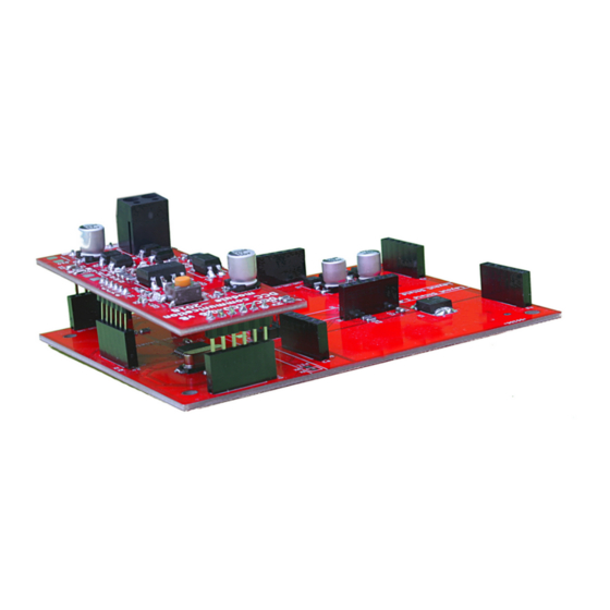
User manual for the Helvest Flex DCC100-E Module
1. GENERAL PRESENTATION OF THE PRODUCT
1.1 Warnings
The boards are not toys and are not suitable for children under 14 years of age. They
contain small pieces that can be swallowed.
Do not leave the product unattended in a position accessible to children.
Read the instructions for use carefully before using the boards.
Take care to make the electrical connections as described. Incorrect connections can
cause damage to the circuit boards or be dangerous to the user.
Under no circumstances must the products be powered in any mode different from those
specified in the instructions, and in particular never exceed a voltage of 16V. Power
supply with inadequate voltages can lead to serious risks for the user and fire hazard.
The product has functional edges and sharp parts.
Do not leave the product powered without supervision.
At the end of the product's life cycle, do not throw it in the waste but dispose of it
according to the provisions for WEEE waste.
1.2 Declaration of conformity
We, Helvest Systems GmbH, Route des Pervenches 1, CH-1700 Fribourg (Switzerland),
declare under our responsibility that the products:
Description and number: HP100, DCC100, ES400, GAW400, UPW400
comply with the requirements of the Electromagnetic Compatibility Directive
(2004/108/EG).
The product complies with the
standards of the harmonised
standards EN55032:2015 and
EN55024:2010+A1:2015.
1.3
Using
the
DCC100
module
This module is part of the Helvest Flex system and allows you to easily mount an
accessory box and flexibly configure it according to your needs.
The module works in combination with an HP100 motherboard (figure 1). It must be
connected by inserting it into the "net" type housing. Please take care to insert it with the
correct alignment without forcing the connectors.
This module deals with communication with any DCC control unit, i.e. it receives its
commands (any control unit conforming to the DCC standard is required) to control
switches, signals or other accessories on the layout of the through the "layout" modules.
1.4 How to install the module
MAX 20V
Fig. 1
Fig.2
NET Module DCC100-E - User Manual
DCC100-E
1.0
Programming ouput
Programmierausgang
PROGRAM MODE
Your DCC central
Ihre DCC Zentrale
The DCC100-E module
must be connected to
the two wires coming
from the control unit
and carrying the DCC
signal. The wires can be
different for program-
ming
and
normal
operation. The power
wires, on the other
hand,
should
be
connected to the HP100
board. Fig. 2 shows an
example of connections
for the programming
step.
For
normal
operation, instead of the
programming
output,
connect to the DCC100-
E the same wires that
are connected to the
track. The module is
now ready to receive
signals from the control
unit.
Advertisement
Table of Contents

Related Manuals for Helvest DCC100-E


Summary of Contents for Helvest DCC100-E
- Page 1 NET Module DCC100-E - User Manual User manual for the Helvest Flex DCC100-E Module This module is part of the Helvest Flex system and allows you to easily mount an accessory box and flexibly configure it according to your needs.
- Page 2 - The flashing of LED no. 3 on the DCC100-E module (fig. 2) means that it is responding address 2, no other accessory can have that Access./Zubehör 1 to the control unit during programming.
- Page 3 (1 second = 50, the maximum value 255, corresponds to about 5 seconds). for the smaller addresses. You can find the complete table on our website www.helvest.ch The CV37 sets the time valid for all outputs of the Layout1 module and the CV38 sets the switching time for all outputs of the Layout2 module.
- Page 4 NET Module DCC100-E - User Manual 3. CV AND ADDRESSES TABLES Values for "Layout Values for "Layout For both modules 1" module 2" module 3.1 List of supported CVs Output address Decoder address CV 1 CV 9 CV 35 CV 36...
- Page 5 An incorrect address was set by mistake. Program CV1 and The complete table can be downloaded from www.helvest.ch CV9 with a new address (see chapter 2). The choice of having two possible ways to activate the accessories depends on the Some parameters have been set incorrectly due to an error.
- Page 6 In the case of large systems it is possible to reprogram the CVs of the individual connected to the layout board! Helvest Flex decoders with a very simple procedure that allows to minimize the electrical connections. 5. ADVANCED SETTINGS (for experienced users) 1) Prepare an additional DCC100-E module dedicated to programming.
Need help?
Do you have a question about the DCC100-E and is the answer not in the manual?
Questions and answers