Advertisement
Quick Links
Helvest
User manual for Helvest
1. General product presentation
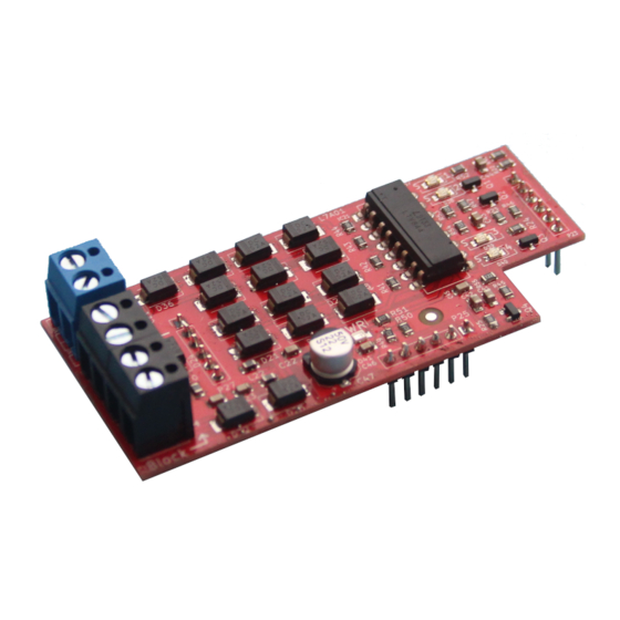
1.1 AB400 train detection feedback module
The AB400 board is a module that detects the location of trains on up to 4 sections of
track, using current-absorption technology: this means that it detects where the train
is based on where, on the track, it picks up current.
This is a layout module for the HP100 motherboard. It must be plugged into the
'layout' connectors of the HP100 board and is automatically recognised by it.
To insert the module, switch off the HP100 board's power supply, ensure that the
connectors are aligned, and apply light pressure until the module is fully inserted
into the slot.
1.2 Preparation of sections
In order to identify whether
the train is on a certain
track
or
in
a
certain
position, the corresponding
tracks
must
first
be
electrically separated.
To
section
the
tracks,
proceed as follows:
- Conventional "two-rail"
power
supply:
interrupt
only one of the two rails,
either by using insulated
joints, or simply by cutting so that the rail sections are electrically insulated (figure
1A).
- "Three-rail" supply systems: with appropriate insulation ( red in the drawing)
interrupt the central conductor in the sections of interest (figure 1B)
®
FleX AB400 board
Fig. 1
FleX Layout module AB400 - User Manual
1.3 Electrical connections
All the following operations must
be performed with the power
switched off.
The HP100 motherboard must be
powered with any voltage from 7
to 20V AC, or 7 to 16V DC. A
digital bus such as DCC is also
suitable,
although
for
large
layouts this is not recommended
(fig. 2)
A 'net' module suitable for data
transmission must be mounted on
the HP100, such as the MVnet
MV100 module or other modules
that will be available in the future.
Fig.
3
shows
the
AB400
connectors in detail. In connector
(1), indicated with COM, must be
inserted the wire common to all
sections, coming from the booster
or the digital control unit. In figure 2 this wire is shown in black.
Connector (2) has the contacts for the four block sections, numbered 1 to 4: these
wires must go to the sectioned rails, also shown 1 to 4 in figure 2.
The unsectioned rail ( marked with the red wire in fig. 2) is to be connected directly
to the control unit or booster.
The track sections where presence is to be detected can be either digital or analogue.
After connecting the tracks as in fig.2, before setting up the board on MVnet, power
up the decoder and the layout and run a train on the connected block sections. The
yellow LEDs in positions 3 and 4 light up as the train runs.
1
3
2
AB400
7-20 V
MV100
1
2
5
Fig. 2
4
Control unit /
Centrale/
Booster
3
4
Fig. 3
Advertisement

Related Manuals for Helvest FleX AB400


Summary of Contents for Helvest FleX AB400
- Page 1 Helvest FleX Layout module AB400 - User Manual Fig. 2 User manual for Helvest ® FleX AB400 board 1.3 Electrical connections 1. General product presentation All the following operations must be performed with the power 1.1 AB400 train detection feedback module switched off.
- Page 2 Helvest FleX Layout module AB400 - User Manual The LEDs at positions no. (3) and (4), numbered 1 to 4, indicate the presence in the 4 sections of the board. If there are no locomotives or vehicles drawing current, the WARNING: It is imperative to connect on the same AB400 module wires coming lights must be switched off.
- Page 3 Helvest FleX Layout module AB400 - User Manual For this purpose, it is sufficient to equip the tail vehicle with a resistor on one axle, which makes contact between the two wheels (fig. 5). We recommend a resistor Problem Possible causes value of around 5 kΩ.
- Page 4 Helvest FleX Layout module AB400 - User Manual "Helvest" is a registered trademark owned by Helvest Systems GmbH, Fribourg (CH). * The names indicated with an asterisk are registered trademarks of other User Manual rev. 1.0 (2023). manufacturers, the property of their respective owners.
Need help?
Do you have a question about the FleX AB400 and is the answer not in the manual?
Questions and answers