Table of Contents
Advertisement
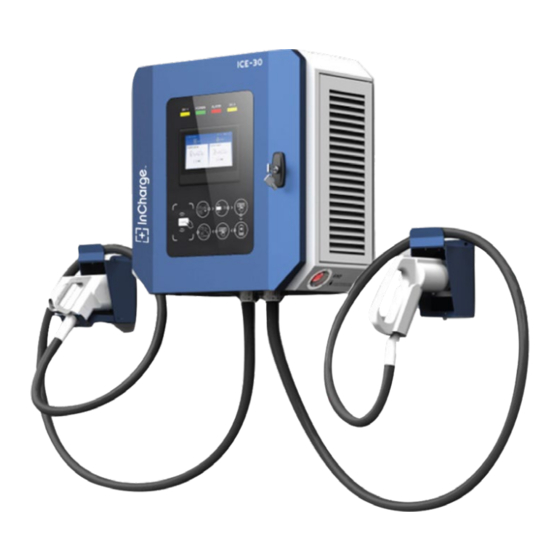
ICE-30
30kW DC Fast Charger
Description
ICE-30 is a compact DCFC capable of charging with one or two connec-
tors and supports both CCS and CHAdeMO standards. This DC Wallbox
is designed for easy wall mounting or can be attached to our pedestal
which includes cable management and convenience lighting. The ICE-30
is easy to operate with an intuitive touchscreen display and is ideal for
auto dealers, fleet charging and a variety of parking applications where
shorter charge times are necessary.
Key Benefits and Features
•
150 to 1000Vdc output voltage range
•
30kW rated output power
•
User friendly control interface allows for access management via PIN or RFID
accessibility
•
OCPP 1.6 standard supports interoperability across backend platforms
•
LTE Modem and LAN
•
Compact design is easy to mount on walls or on the optional InCharge pedestal
•
TUV certification to UL 2202 to ensure safety
•
480V 3-phase input for high efficiency conversion
Specifications
•
Available with CCS1 and CHAdeMO
•
DIN 70212 and ISO 15118-2 protocol supported
•
Hot galvanized steel, plastic facade, and tempered glass screen construction ensures longevity
•
Dimensions (D x W x H): 10.63" x 24.00" x 24.00" / 270 mm x 610 mm x 610 mm
•
Weight: 194lbs / 88kg
The ICE-30 Dual CCS
Advertisement
Table of Contents

Related Manuals for InCharged ICE-30


Summary of Contents for InCharged ICE-30
- Page 1 30kW DC Fast Charger Description ICE-30 is a compact DCFC capable of charging with one or two connec- tors and supports both CCS and CHAdeMO standards. This DC Wallbox is designed for easy wall mounting or can be attached to our pedestal which includes cable management and convenience lighting.
- Page 2 Ordering Information Configuration ICE-30 - CC IDC-30-480-C1C1-WC1R ICE-30 - CJ IDC-30-480-C1CH-WC1R ICE-30 - CC Cold IDC-30-480-C1C1-WC1R-CW Weather IDC-30-480-C1-WC1R ICE-30 - C ICE-30 - C1L IDC-30-480-C1L-WC1R ICE-30 - CC CCR IDC-30-480-C1C1-WC1C ICE-30 - C1LC1L IDC-30-480-C1LC1L-WC1R...
- Page 3 Technical Specifications Configuration Voltage 480Vac WYE, +/- 10 % AC Input Power Connection 3-phase: L1, L2, L3, GND Frequency 45-65 Hz Recommended breaker 50A 3W+G circuit SCCR 10 kAIC Max Current Draw Power factor >0.99 THD - Current < 3% Output Parameters Value Voltage...
- Page 4 ICE-30 Fast DC Charger Installation and Operation Manual Version: 2 Last Time Edited: 2/23/2023 In-Charge Energy Inc. All rights reserved. This manual may be subject to change without notice. https://inchargeus.com/ Service hotline: 818-697-GOEV...
- Page 5 IMPORTANT SAFETY INSTRUCTIONS Please read the operating instructions and notes carefully before starting operation in order to prevent accidents. The "Caution, Attention, Warning and Danger" statements in the products and product manual do not represent all safety matters to be observed and are intended to supplement various operational safety precautions.
- Page 6 Static Electricity Static electricity generated by the human body may damage electrostatic sensitive components on the circuit boards, such as the large-scale integrated circuit (IC), etc. Before handling any patch boards, circuit boards and IC chips, it is necessary to wear an anti-static wrist strap with the anti-static wrist strap wire connected to Ground to avoid damage to sensitive components due to static electricity.
-
Page 7: Table Of Contents
Table of Contents 1 General Product Description ........................5 2 General Characteristics ..........................5 Technical Specification ......................... 5 2.3 Model description ..........................7 2.4 Standards ............................. 7 3 Product Parts Presentation......................... 8 4 Installation ..............................9 Grounding instructions ........................9 Unpacking and visual inspection ...................... -
Page 8: General Product Description
1 General Product Description The ICE-30 Series Wall Box DC Charger is able to fast charge all electric vehicles compliant with CHAdeMO charging system and combined charging system (CCS) standards. Designed to be wall mounted or pedestal mounted, this model is lightweight and versatile. - Page 9 Technical Data Description Remarks Phases/Lines 3 phases Wye + PE Voltage 380Vac-520Vac (+/-10%) Frequency 50 – 60 Hz Nominal Input Current Power 31.5kW Power factor ≥0.99 ≥ 94.5% (Full load) System Efficiency 50A 3W+G Circuit Recommended Breaker Electrical Safety 10 kAIC SCCR Voltage 150~1000Vdc...
-
Page 10: Model Description
2.3 Model description NRTL Model Number Model Configuration Remarks IDC-30-480-C1C1-WC1R 30kW ICE-30-CC CCS-1 + CCS-1 IDC-30-480-C1CH-WC1R ICE-30-CJ CCS-1 + CHAdeMO 30kW 2.4 Standards The EVSE (Electric Vehicle Supply Equipment) complies with the following standards: Table 2 Applicable Standards Technical Data... -
Page 11: Product Parts Presentation
3 Product Parts Presentation The charging system is composed of DC charging cabinet and DC charging connector. The System can be installed outdoors. The ICE-30 fast DC Charger has various possible output combinations as shown below : Figure 1: External View of ICE-30... -
Page 12: Installation
4 Installation 4.1 Safety and compliance Since the working voltage inside the charging system is very high and the current is very large, the following rules should always be observed to ensure personal safety: Only personnel who have received the training of the charging system and fully mastered the knowledge of the charging system can install the charging system. - Page 13 Figure 2: Drilling and Conduits layout Figure 3: ICE-30 Space Requirement...
- Page 14 4 pcs Between the gun holster and the wall Expansion screw, M6 * 16mm 3 pcs/gun M6 * 16, 6pcs Combination Screw Backplane Body Figure 4: ICE-30 Bracket bolt pattern M8 * 30, 4pcs Expansion Screw Figure 5: Grid input wiring...
- Page 15 M6 * 16, 4 pcs Expansion Screw Figure 6: Back hole dimensions...
- Page 16 Figure 7: Concrete foundation view Figure 8: Top view...
-
Page 17: Power Cables Connections
4.4.3 Power cables connections End terminals for input wiring: 4 (four) end terminals for 3 phases + protective ground. Figure 9: AC Input Wiring Table 4-AC input wiring cables The section for AC Max. Power Specification of Amperage feed cables of charger terminal screw L1/L2/L3 is M6... - Page 19 Figure 10: UL Wiring Diagram ※ PE: Earth Bus Bar ※ XT1: Power main input-Terminal Block: L1 L2 L3 N ※ Q1: AC Input MCB For Rectifier Module ※ Q2: AC Input RCD For Auxiliary Power ※ Q3: AC output-power main input MCB ※...
- Page 20 STEP-2 STEP-1 STEP-4 STEP-3...
- Page 21 ※ Step-1:Remove the nuts in the cabinet (marked with a red circle). ※ Step-2: Insert the power module ※ Step-3: Tighten the retaining screw to secure the module. ※ Step-4: Set the Address of the power module (marked with a red rectangle), follow the below picture.
-
Page 22: Start-Up
5 Start-Up 5.1 Verification and inspection Check if the bolts of the AC and protective ground cables of the EVSE are correctly tightened to the specified torque. The torque values are as follows: M8: 8ft-lbs M6: 36in-lbs Check the resistance between the EVSE protective ground and the low voltage switchboard ... - Page 23 Wait for a few seconds. The display will present a picture as below Figure 2: Loading Screen Finally, the display will present the following charging screen CCS1+CHAdeMO Units: Figure 3: Charging screen Before attempting to install or start up the charger must ensure that the safety instructions in this manual have been carefully read and observed by trained personnel.
-
Page 24: User Manual
6 User Manual The EVSE operation depends on its output connections: CCS or CHAdeMO. During the charging process, the Human Machine Interface (HMI), will give instructions and will signal different stages. These sequences are shown in this chapter. 6.1 Output connector The EVSE is prepared to charge electric vehicles according to the mentioned charging systems 6.1.1 CCS Connector Combo TYPE1... -
Page 25: Operation Instructions
6.2 Operation instructions When a user starts an operation on the EVSE, the HMI display will show one of the following screens. CCS1+CHAdeMO Units: 1、Plug the charging gun into the vehicle receptacle. 2、Press “Ready” on the screen. 3、Wait for the charging session to begin. 4、After the vehicle is fully charged, stop charging first, then unplug the charging gun. - Page 26 6.3 Operation Indicator Lights The Indicator lights that are located above the screen show the chargers current state. Light Info:...
-
Page 27: Appendix 1 Engineering And Technical Parameters
※ Hot ventilation air exits to the left. A minimum 40in (1000mm) clearance should be provided to prevent hot air from recirculating back to the air intake. Note: When the system is running, the temperature of the left-side door will be hot so avoid contact. Figure 6: ICE-30 side views... - Page 28 Figure 7: EVSE Space Requirement...
- Page 29 Appendix 3: Maintenance 1 Maintenance Table Position Method Tool Maintenance cycle AC Input for Auxiliary Power Visual Check 2 months Devices and connection points: Main circuit devices (circuit breaker, AC contactor, DC contactor, DC fuse), Visual Check Torque Wrench 2 months copper bar, power module connector AC SPD Visual Check...
- Page 30 2.2 Devices and connection points 1) Check the connection points(circle in the picture)between the main circuit components (circuit breaker, AC contactor, DC contactor, fuse) and copper bar or cable, the connection points between copper bar and copper bar, and the connector of power module for burns or serious discoloration. If damage is found please check the torque and connection according to point 2) and replace the damaged components if required;...
- Page 31 2.3 AC SPD Check the status window of SPD. If the window color changes from green to red, it indicates that SPD has been detected, contact the manufacturer for replacement Status Window 2.4 Charging plug 1) Check whether the charging plug is cracked or damaged. If so, please contact the manufacturer. 2) Check whether the DC + and DC -terminals of the charging plug have obvious burning marks.
- Page 32 2.5 Cooling Fan and Filter cotton 1) Check the dust screen on both sides of the heat exchanger for dust. 2) Use the a brush or cloth to clean the dust on the dustproof net. 3) Depending on the site environment, the dust net shall be effectively removed at least once every three to six months, and it shall be replaced once a year at most.
-
Page 33: Alarm Information
Appendix 3: Alarm information 1) Click “?” In the upper right corner of the screen to view the error code/alarm information. 2) If an alarm is displayed it should be addressed immediately. If it cannot be resolved, contact the manufacturer for assistance. Click here to view alarm information... -
Page 34: Appendix Error Codes And Possible Solutions
Appendix 4: Error codes and possible solutions... - Page 35 Table: Charger_Alarms Alarm_ID Alarm_Name Alarm_Level Description Remark System is out of service and charge is not allowed. System Not This usually comes after Available other critical alarm(e,g EPO pressed) System is out of service and charge is not allowed. System Disabled This happens after system is set to 'In-operative' by service guy or backend.
- Page 36 is over the upper limit point(default is 75 'C) This means system not All Rectifier Failure available All Rectifier Comm This means system not Fail available Rectifier group 1/2 This means the specified Rectifiers Failure gun will not be available shall be specified Rectifier group 1/2 be Rectifiers Comm...
- Page 37 wiring for the current shunt. - Critical alarm - Major alarm - Observative Alarm Stop Reason Code Description Remark Classification Normal Stop Condition satisfied Normal Stop EV Request Stop EV Request Stop Parameter configuration failed Charging Enable timeout Abnormal volt of outside bus Unable lock charging gun Insulation inspection anomaly Insulation inspection timeout...
- Page 38 AllRectFail MainsFailAlm AlRectCommFail E_LockFail GunOverTemp OutputShortCircuit PWM Failure Ground Fault Detected CR Comm Fail kWhMeterComm Fail CCU Comm Fail Battery overvoltage Battery undervoltage Battery current deviation error High battery temperature Battery voltage deviation error Charger Connector Lock Fault EV Error Vehicle shift position Error Status Noticed by EV PLC Low Level Comm Fail...
- Page 39 Reboot DeAuthorized One-Click Stop Hard Reset Soft Reset Other Other...
Need help?
Do you have a question about the ICE-30 and is the answer not in the manual?
Questions and answers