Table of Contents
Advertisement
Quick Links
Advertisement
Table of Contents

Related Manuals for INVENTIA MT-151


Summary of Contents for INVENTIA MT-151
- Page 2 Telemetry Module MT-151 LED V2 User Manual GSM/GPRS Telemetry Module for monitoring and control Class 1 Telecommunications Terminal Equipment for GSM 850/900/1800/1900 UMTS 800/850/900/1900/2100 INVENTIA Sp. z o.o. v2.03...
- Page 3 Mobicon MT-151 LED V2 User Manual © 2019 Inventia Sp. z o.o. Wszelkie prawa zastrze one. aden fragment niniejszego dokumentu nie mo e być powielany lub kopiowany w adnej formie bez względu na stosowaną technologię – graficzną, elektroniczną lub mechaniczną, włączając fotokopiowanie i/lub zapis cyfrowy, równie w systemach przechowywania i wyszukiwania dokumentów –...
- Page 4 4 Analog inputs 0-10V ........................... 13 5 Communication ports ........................... 14 6 GSM antenna ........................... 15 7 SIM card installation ........................... 16 8 SD memory card installation ........................... 17 9 Power supply ........................... 18 © 2019 Inventia Sp. z o.o.
-
Page 5: Table Of Contents
Mobicon MT-151 LED V2 User Manual Starting the module VIII Interfaces and communication methods 1 Serial ports ........................... 21 Transparent m ode ................................21 Modbus Master m ode ................................21 Modbus Slave m ode ................................22 Flex Serial ................................22 M-Bus ................................ - Page 6 Impulse w eight - divider ................................. 50 Offset - engineering units ................................. 51 Hi alarm - engineering units ................................. 51 Lo alarm - engineering units ................................. 51 Alarm hysteresis - engineering units ................................. 51 © 2019 Inventia Sp. z o.o.
- Page 7 Mobicon MT-151 LED V2 User Manual Binary outputs (Q1 - Q12) ................................52 Name ................................. 52 Input type ................................. 52 Filtering ................................. 52 Analog inputs 4-20m A (AI1 - AI4) ................................52 Sampling frequency ................................. 52 Name ................................. 53 Engineering units .................................
- Page 8 IP address ................................. 75 Subnet mask ................................. 75 Default gatew ay ................................. 76 IP routing table entry count ................................. 76 Routing IP ................................. 76 Authorized IP addresses ................................. 76 Number of IP addresses ............................76 © 2019 Inventia Sp. z o.o.
- Page 9 Mobicon MT-151 LED V2 User Manual ............................76 Modbus TCP Client ................................. 77 Delay after error in communication w ith Server ............................77 Number of read/w rite data blocks ............................77 Response timeout ............................77 Ethernet IP ............................78 Server Modbus ID ............................
- Page 10 GSM activity ................................100 Serial ports activity ................................100 Ethernet status ................................100 Module status ................................101 2 MT-151 LED Error signaling ........................... 101 Standard errors ................................102 3 Unlocking the SIM card ........................... 103 Technical parameters 1 General ........................... 104 2 GSM modem ...........................
- Page 11 Mobicon MT-151 LED V2 User Manual VIII 8 Drawings and dimensions ........................... 106 Safety information 1 Working environment ........................... 107 2 Electronic equipment ........................... 107 Heart pacem akers ................................107 Hearing aids ................................107 Other m edical equipm ent ................................107 RF Marked equipm ent ................................
- Page 12 With compact, robust design, integral GSM modem, attractive technical features and easy to use configuration tools the MT-151 LED controller is an optimal solution for demanding wireless telemetry, control, diagnostic, surveillance and alarm systems.
- Page 13 Using the module in places where the signal is weak may lead to interruptions in transmission and possible loss of transmitted data along with increased costs generated by transmission retries. © 2019 Inventia Sp. z o.o.
- Page 14 Chapter contains signaling description of LED indicators which is necessary knowledge during module installation. Module connection diagrams - contains diagrams and procedures for connecting MT-151 with devices and external elements like sensors, antennas or the SIM card. First start of the module - contains recommended first start procedure.
- Page 15 MT\ML module management. Program allows a local and remote configuration of the modules, programing of control algorithms, firmwares upgrade and resources monitor. Application is available on MT-DISC, the DVD that is delivered with MT-151 or can be downloaded after login on www.inventia.pl web site.
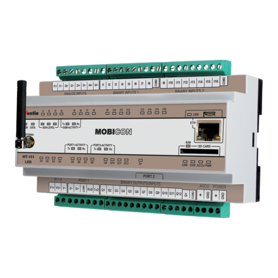
- Page 16 Mobicon MT-151 LED V2 User Manual Module design Hardware resources I1 - I16 binary inputs Q1 -Q12 binary outputs that can operate as binary inputs AI1 - AI4 4-20mA current analog inputs AV1 - AV2 0-10V voltage analog inputs PORT 1...
- Page 17 5.1.7 USB port MT-151 LED telemetry module is equipped with USB (micro USB B) port which is used for device configuration (MTManager is required). This Port is visible in system (driver only for Windows) as COM port. Device communicates at 115200 bps with 8 data bits, no parity bit and 1 stop bit.
- Page 18 5.1.9 Real time clock MT-151 LED module is equipped with Real Time Clock (RTC). This clock is a source for time measurement for the module timers and time stamping measurements stored in the logger and sent via GPRS.
- Page 19 5.2.6 Constant parameters In MT-151 LED module configuration user can define up to 128 constant parameters - 16-bit values in range from -32768 to 32767 that may be further used for control program parameterization. Values of constant parameters are nonvolatile.
- Page 20 Mobicon MT-151 LED V2 User Manual · The execution of program cycle starts every 100 ms. Duration between cycles is count from beginning of first cycle to beginning of second. Run time length of the program not affect for next cycle until it exceeds 90ms. If program loop executes longer than 90 ms (in case of write/erase flash memory of logger, large CPU processing load like lot calls of float function), next cycle will start immediately after ~10ms.
- Page 21 Module design MTManager - sample program in MTprog mode LEDs LED indicators placed on MT-151 LED front panel are a great help during module startup and troubleshooting. Detailed description of LED signaling can be found in LED signaling chapter. SIM cards slots MT-151 LED module is equipped with two SIM card slots that allow installing two miniature SIM cards (not micro!).
- Page 22 Mobicon MT-151 LED V2 User Manual Connection diagrams This chapter presents recommended wiring of external signals and installation procedure of the components. Binary inputs Binary inputs I1 - I16 in positive logic: Binary inputs I1-I16 for proper operation, require connection the power to Q+...
- Page 23 Signal cables length should be < 30m · For longer cables it is advised to use external overvoltage protection Analog inputs 4-20mA Analog input AI1 - connection with active sensor: Analog input AI1 - connection with passive sensor: © 2019 Inventia Sp. z o.o.
- Page 24 Mobicon MT-151 LED V2 User Manual Attention! · Power cables length should be < 10m · Signal cables length should be < 30m · For longer cables it is advised to use external overvoltage protection Analog inputs 0-10V Analog input AV1 - connection with active sensor:...
- Page 25 Receiver input 5 – RTS Handshake output (Ready To Send) 6 - CTS Handshake input (Clear To Send) Ethernet port - optoisolated 10Base-T/100Base-TX communication port. Port connector (RJ- 45) is located on the front panel. © 2019 Inventia Sp. z o.o.
- Page 26 Not connected 8 - NC Not connected GSM antenna Connecting the antenna is necessary for reliable data transmission from MT-151 LED module. SMA female type antenna socket is placed on the module front panel. © 2019 Inventia Sp. z o.o.
- Page 27 SIM card installation MT-151 LED module is equipped with two SIM card slots that allow installing two miniature SIM cards (not micro!). For GPRS transmission it is advised to use static IP addressed SIM cards as it allows communication between devices and not only server and device. Module supports a low voltage 3.3V SIM cards.
- Page 28 Mobicon MT-151 LED V2 User Manual SIM Cards slots are on the left side of module's enclosure SD memory card installation SD memory card has to be slip in the gap narrow side facing toward the memory socket until a click.
- Page 29 For longer cables it is advised to use external overvoltage protection NOTICE! Due to high peak current of MT-151 LED power supply should be able to deliver current >= 2A. Improper power supply may results in faulty operation and can damage the module! ©...
-
Page 30: Starting The Module
Mobicon MT-151 LED V2 User Manual Starting the module First start of the MT-151 LED module requires a few simple activities. Please follow steps listed below: 1. Connect signal wires and GSM antenna Recommended connections diagrams for signal wires and the antenna are in Connection diagrams chapter. - Page 31 Clock of the module with the computer clock. It is crucial since lack of synchronization may result with faulty time stamping of the data in logger and may lead to data loss. More information about time synchronization is in MTManager user manual. © 2019 Inventia Sp. z o.o.
-
Page 32: Interfaces And Communication Methods
Please read carefully description of every mode, it is necessary for proper choosing the right mode for best use of MT-151 LED Next chapters describe a local and remote communication for data sharing between other devices on long distance. -
Page 33: Modbus Slave Mode
8.1.3 Modbus Slave mode In this mode MT-151 LED module acts on this port as Modbus RTU Slave device and waits for incoming Modus RTU commands. It will react on command that is send to ID matching ID of MT- 151 LED for that port. -
Page 34: M-Bus
The protocol is available only on port RS-232. This feature is developed in the module for directly operations with devices that support the M-Bus protocol which are used mainly in energy consumption measurements. Direct communication between MT-151 LED module and M-Bus devices require use an external electrical M-Bus converter that have to be connected to PORT 1. -
Page 35: Ethernet Port
SMS, GPRS transmission, control program or any other method, this new data will be written to Server. In this mode MT-151 LED is using Modbus TCP functions 1, 2, 3 and 4 for polls and 5, 6 for writes. -
Page 36: Modbus Tcp Server
MT-151 LED operates as is server listening on port 502 and waits for Modbus TCP frames. It will react on command that are send to ID matching ID of MT-151 LED for that port. Incoming Modbus TCP commands can be routed to other ports or GPRS according to routing rules defined in Modbus routing table thus allowing to communicate devices connected to different ports. - Page 37 Inventia is using ID 42317. Variable tree structure is defined as a MIB data base and can be saved in text files using ASN1 (Abstract Syntax Notation One) notation. Variable tree MT-151 LED has structure as below: Sending unsolicited data (Traps) Trap is a data packet send from device containing device ID, device IP address, timestamp and Specific ID (trap ID).
-
Page 38: Iec 60870-5-104 Protocol
Changing the setting of parameter in configuration allows to turn on the IEC time synchronization if necessary. First connection of the client to MT-151 LED after reset makes a reply by sending the "end of initialization" (M_EI_NA_1) message. - Page 39 Client site timeout T2 between 3 … 5 seconds and W parameter to 4 or 5 value. Events prepared in configuration use Current sending buffer but they are stored in non-volatile memory and can be sends with delay in case of temporary exceeding a capacity. © 2019 Inventia Sp. z o.o.
-
Page 40: Configuration
Mobicon MT-151 LED V2 User Manual Configuration MT-151 LED just like other MT devices is configured by using MTManager (MTM) which is provided for free with all MT equipment. MTManager is an unified program environment that allows setting up and maintaining whole telemetric system or systems regardless of its scale. -
Page 41: Module Serial Number
- The value of this parameter increases automatically by 1 after each successfully written configuration. 9.1.9 Last configuration date Function - Displays date and time of last successful configuration change Data type - Text © 2019 Inventia Sp. z o.o. -
Page 42: 9.1.10 Last Reading Time
Mobicon MT-151 LED V2 User Manual Range - N/A, read-only parameter Comments - The value changes automatically after each successful configuration change. It is useful for tracing unauthorized configuration changes. 9.1.10 Last reading time Function - Displays internal module time recorded during last... -
Page 43: Configuration Password
- Defines UDP port on which the responses frames shall be sent. Data type - Number Range - 1024 - 65535 Default value - 7110 Comments - Answers for MT-Data Provider data requests will be sent on this port number. © 2019 Inventia Sp. z o.o. -
Page 44: Udp Data Frame Format
Mobicon MT-151 LED V2 User Manual 9.2.7 UDP data frame format Function - This parameter selects data frame type used by module for GPRS communication Data type - Selection list Range - MT Standard Module communicates using the protocol and transmission protection created by Inventia. -
Page 45: Module Phone Number (Sim1/Sim2)
- Defines transmission channel for time synchronization requests. Data type - Selection list Range - GPRS NTP request is sent via GPRS packet transmission interface. Ethernet NTP request is sent via Ethernet interface. Default value - GPRS © 2019 Inventia Sp. z o.o. -
Page 46: 9.2.14 Address
Mobicon MT-151 LED V2 User Manual Comments - N/A 9.2.14 Address Function - Selects the NTP server IP address. Data type - Selection list Range - Numbers defined in GSM -> Authorized numbers -> IP list for data transmission Default value... -
Page 47: Use Of Sms
Caution is vital, when setting the PIN code value. Entering incorrect PIN code may cause modules start-up impossible and lock SIM card. For security reasons module makes attempt to enter PIN code twice. To unlock SIM card please follow procedure described in Problem solving chapter. © 2019 Inventia Sp. z o.o. -
Page 48: Apn Name
Mobicon MT-151 LED V2 User Manual 9.3.4.3 APN name Function - Defines APN name which is used by module to carry out GPRS transmission using that SIM Data type - Text Range - Letters, numerals and special characters - max. 32... - Page 49 - When this field is left at default value 0.0.0.0 remote communication with the module is possible using other IP addresses. Obviously IP address can be inserted manually to allow access to remote module via that SIM card if is logged. © 2019 Inventia Sp. z o.o.
- Page 50 Mobicon MT-151 LED V2 User Manual 9.3.5.2 SIM card PIN number Function - Defines PIN access code for SIM module delivered by GSM operator. For SIM modules not protected by PIN code, the value is insignificant. Data type - Text...
- Page 51 This is possible only when the SIM card in module has the roaming service enabled. 9.3.6 GPRS GPRS contains parameters applying to GPRS communication handling valid for both SIM cards. © 2019 Inventia Sp. z o.o.
- Page 52 - 0.01 - 655.350 [s] Default value - 5.00 [s] Comments - N/A 9.3.7 SMS contains parameters related to sending and receiving of text messages by MT-151 LED module. 9.3.7.1 Daily SMS limit Function - Defines maximum quantity of SMS, the module may send during one day.
- Page 53 - In replay message text may be used symbolic names and macros following syntax rules defined in Appendices in the SNCS commands syntax chapter. 9.3.7.6 Incoming SMS handling Function - allows to choose how will be handled SMS messages, © 2019 Inventia Sp. z o.o.
- Page 54 Mobicon MT-151 LED V2 User Manual Data type - selection list Range - By system Module received SMS messages, system program process the content according to SNCS syntax, settings of macros and symbolic names created by user. System automatically check authorized phone numbers and realize commands and orders included in the message.
- Page 55 Next registers will store next signs of the message content. Data type - Number Range - 0 - 8000 Default value - 1400 Comments - N/A © 2019 Inventia Sp. z o.o.
- Page 56 Mobicon MT-151 LED V2 User Manual 9.3.7.10 Buffer address holding receiver phone number (HREG) Function - address [dec] in holding register space determine first register where the first digits of the receiver's phone number will be stored. Next registers will store next digits of the phone number string.
- Page 57 9.3.7.13 Macros Macros group contains up to 16 user-defined macros. Macro may contain ASCII signs, symbolic names, SMS commands and other macros that will be put in SMS text. In order to use a macro © 2019 Inventia Sp. z o.o.
- Page 58 Mobicon MT-151 LED V2 User Manual in SMS put place there a name preceded by '*' sign in SMS text send from mobile phone to module or in SMS text sent from module or other macro. Using macros makes composing complex SMS texts and queries much more convenient and user friendly.
- Page 59 IP will be accepted or ignored Default value: (allowed) SNMP Query - Value of this parameter determines whether SNMP request arriving from selected IP will be accepted or ignored Default value: (not allowed) © 2019 Inventia Sp. z o.o.
- Page 60 Mobicon MT-151 LED V2 User Manual Resources Group Resources encompasses a list of hardware and software resources available to users. 9.4.1 Binary inputs (I1 - I16) All parameters listed in this group are set individually for each binary input. Binary inputs operate in both positive and negative logic at the same time.
- Page 61 - flow value Impulse weight - Multiplier (eng. units) b - Impulse weight - Divider (eng. units) Offset (eng. units) Available for Counting input as selection type of Input for I1 - I4. © 2019 Inventia Sp. z o.o.
- Page 62 Mobicon MT-151 LED V2 User Manual 9.4.1.8 Offset - engineering units Function - Allows for result correction of the flow by subtracting constant value Data type - Number Range - 0 - 1000 Default value Comments - The calculated value of the flow is outcome a...
- Page 63 This parameter is available in binary input mode only. 9.4.3 Analog inputs 4-20mA (AI1 - AI4) MT-151 LED is equipped with four current analog inputs operating in 4-20mA range. All parameters but sampling frequency are set individually for each input. 9.4.3.1...
- Page 64 Mobicon MT-151 LED V2 User Manual New measurement is available every second. Measurement is slower but more precise - resolution is nearly 20000 units (above 14 bits). This setting is advised for low-dynamics signals. 10Hz New measurement is available every 100 milliseconds.
- Page 65 9.4.3.10 Lo alarm - engineering units Function - Defines Lo alarm level for analog signal value in engineering units. Data type - Number Range - -32768 - 32767 Default value - -32768 © 2019 Inventia Sp. z o.o.
- Page 66 - data is send only when analog input changes. 9.4.4 Analog inputs 0-10V (AV1 - AV2) MT-151 LED is equipped with two voltage analog inputs operating in 0-10V range. All parameters are set individually for each input. 9.4.4.1 Name...
- Page 67 High reference - internal units parameter Data type - Number Range - -32768 - 32767 Default value - 10000 Comments - Used along with other reference parameters for rescaling input signal to engineering units. © 2019 Inventia Sp. z o.o.
- Page 68 Mobicon MT-151 LED V2 User Manual 9.4.4.7 HiHi alarm - engineering units Function - Defines HiHi alarm level for analog signal value in engineering units. Data type - Number Range - -32768 - 32767 Default value - 32767 Comments - If value of analog signal is higher than value of this parameter, then the HiHi alarm flag is raised.
- Page 69 1 to 0 Default value - 0->1 Comments - N/A 9.4.5.3 Decrementing input Function - Defines the bit which state change decrements counter value by 1 Data type - Number © 2019 Inventia Sp. z o.o.
- Page 70 Mobicon MT-151 LED V2 User Manual Range - 0 - 65535 or name from bit list (see bit list Appendices) Default value - N/A Comments - Bit addresses 0 - 9999 point to analog inputs/binary inputs address space while addresses 10000 - 65535 point to Internal registers/binary outputs address space.
- Page 71 - Multiple choice field Range - Jan., Feb., Mar., Apr., May, Jun., Jul., Aug., Sep., Oct., Nov., Dec. Default value - Jan., Feb., Mar., Apr., May, Jun., Jul., Aug., Sep., Oct., Nov., Dec. (all months are selected) © 2019 Inventia Sp. z o.o.
- Page 72 Mobicon MT-151 LED V2 User Manual Comments - Timer is active when date and time of module RTC matching following equation: (X OR Y)AND Z = 1, where X=1, when current RTC day of week is selected on Days of week parameter;...
- Page 73 - N/A 9.4.7 Constant parameters Constant parameters are the constant values entered in configuration which can be used within MT-151 LED program what allows to parameterize universal program for application needs. 9.4.7.1 Number of constant parameters Function - Defines number of constant parameters on list...
- Page 74 Mobicon MT-151 LED V2 User Manual Copying is enabled Copying is disabled Default value - No Comments - N/A 9.4.8.2 Start Function - Defines the synchronization point of timer with RTC Data type - Time Range - 00:00 - 23:59...
- Page 75 - Defines operating mode of serial port Port 1 Data type - Selection list Range - Inactive Serial port is disabled Transparent Serial port communication is channeled to other communication port or GPRS network according to rules defined in Transparent routing table. © 2019 Inventia Sp. z o.o.
- Page 76 Slave devices connected to that port using Data blocks. Also polls and writes from external devices communicating with MT-151 LED can be routed to Port 1 according to rules defined in Modbus routing table. Additional configuration parameters are available Modbus RTU Master mode group.
- Page 77 - Defines selection of Modbus protocol type to use Data type - Selection list Range - RTU ASCII ASCII 8bit available option list Default value - RTU Comments - Available only for operating modes: Modbus Master, Modbus Slave © 2019 Inventia Sp. z o.o.
- Page 78 Comments - N/A 9.5.5.9 Modbus Master mode In this mode MT-151 LED can poll for data from and write data to external Slave devices connected to that port using Data blocks. Also polls and writes from external devices communicating with MT-151 LED can be routed to PORT 1 according to rules defined in...
- Page 79 Input registers (address 3XXX) also known as analog inputs address space, read only Holding Registers Holding registers (address 4XXX) also known as internal registers and analog outputs address space, read/write Default value - Binary Inputs Comments - N/A © 2019 Inventia Sp. z o.o.
- Page 80 9.5.5.10 Flex Serial mode MT-151 module with active Flex Serial mode selected in configuration and external device connected to serial port allows communication in protocol different than Modbus. Whole communication in Flex Serial mode is controlled in internal user program. Data transfer between devices is using internal registers that are indicated in memory and operate as two data buffers, read and write.
- Page 81 - selection of an addressing type for devices connected in M-bus. Data type - Number Range - Unicast addressing based on real address of the device or logical addressing based on serial number of the device Broadcast © 2019 Inventia Sp. z o.o.
- Page 82 - N/A 9.5.5.11.4 M-BUS device (DEVx) Group of parameters described request rules of devices that is read by MT-151 with M-Bus protocol. Each device can have separately configuration of addresses, resources and variables for reading. In case of Broadcast addressing, only one position is on the list. Unicast addressing allows connection up to 16 external devices.
- Page 83 Flow temperature, Return temperature, Temperature difference, External temperature, Pressure, Power, Operating time, On time, Extended(VIFE) Unit/VIFE - selection of unit for quantity that will be sent (value is scaled automatically) Range: physical quantities units © 2019 Inventia Sp. z o.o.
- Page 84 Mobicon MT-151 LED V2 User Manual selection Extended(VIFE) allows to enter HEX value with 4 - 16 number of signs for identify of quantity which will be comparison with VIFE field from information data blocks that comes from M-Bus device. Equality of both values is a condition to fill register selected from HREG space.
- Page 85 - No Ethernet port is disabled Ethernet port is enabled. Default value - No Comments - MT-151 LED operates on Ethernet port as Server - it allows remote connection from clients which then can poll © 2019 Inventia Sp. z o.o.
- Page 86 Mobicon MT-151 LED V2 User Manual for data or write to device. When needed module can connects to server as an client and trying to get the data according to Modbus TCP Client data blocks or can transmitting incoming data according to routing tables.
- Page 87 Communication is carried out using UDP protocol Communication is carried out using TCP protocol Configuration Value of this parameter determines whether remote configuration data arriving from selected IP will be ignored or accepted Default value: (allowed) © 2019 Inventia Sp. z o.o.
- Page 88 (allowed) 9.5.6.10 Modbus TCP Client In this group MT-151 LED can poll for data from and write data to external Modbus TCP Slave devices connected to Ethernet port using Data blocks. Polls and writes from external devices communicating with MT-151 LED can also be routed to Ethernet according to rules defined in Modbus routing table.
- Page 89 - setting this value to 0 disables data block 9.5.6.10.8 Mapped space size Function - Defines number of Modbus TCP Server device addresses (bit or register depending on address space) to be mapped to registers of module Data type - Number © 2019 Inventia Sp. z o.o.
- Page 90 Mobicon MT-151 LED V2 User Manual Range - 1 - 2040 Default value Comments - One register count 16-bits: Example of mapping bits: Mapped space address - Module: Mapped space address - Server TCP: 0 Mapped space size: 16 bits form Server goes to register 116 9.5.6.10.9 Mapped space address - Module...
- Page 91 Modbus sensor from picture above is connected to Port 1 serial port and its Modbus ID is 1. It can be accessed from Ethernet by PLC - it should poll MT-151 LED using Modbus TCP protocol © 2019 Inventia Sp. z o.o.
- Page 92 Mobicon MT-151 LED V2 User Manual for ID 7. This poll will be automatically translated to Modbus RTU and send to Port 1 with ID 1. This sensor can also be accessed from GPRS by Server. It should poll for ID 123 to get access to Modbus sensor.
- Page 93 - Defines primary transmission channel for logger data. Data type - Selection list Range - GPRS Logger records are sent using GPRS packet transmission interface. Ethernet Logger records are sent using Ethernet interface. Default value - GPRS Comments - N/A © 2019 Inventia Sp. z o.o.
- Page 94 Mobicon MT-151 LED V2 User Manual 9.6.2.2 Primary Recipient Function - Defines IP address which shall receive logger data frames Data type - Selection list Range - None and addresses defined in GSM -> Authorized numbers -> list for GPRS transmission...
- Page 95 Trigger logger - Toggles sending the logger content on/off on occurring sending event. Default value is (off). 9.6.4 Data blocks Data blocks subgroup contains definitions of data which then can be used send using Rules. © 2019 Inventia Sp. z o.o.
- Page 96 Mobicon MT-151 LED V2 User Manual 9.6.4.1 Number of data blocks Function - Defines the length of the Data block table Data type - Number Range - 0 - 32 Default value Comments - N/A 9.6.4.2 Data block table Idx.
- Page 97 - It is possible to add to SMS text macros, symbolic names and special mnemonics dynamically changed for values from module, e.g. analog input value or binary input state. Description of this mnemonics can be found in commands syntax chapter in Appendices. © 2019 Inventia Sp. z o.o.
- Page 98 Mobicon MT-151 LED V2 User Manual Parameter is visible only when Transmission type parameter is set to SMS. 9.6.5.3.6 Data block Function - Defines data block which is sent via GPRS by rule Data type - Selection list Range - None and events defined in...
- Page 99 - Provides to server information about type of trap event. Basic information for trap meaning distinction by SNMP server. User can set any value from range: 0 - 65535 MIB file provided by Inventia lists several values of parameter: analog input alarm activated new analog input measurement...
- Page 100 1. Status - Defines value which is sent as trapSourceStatus variable. User can set any value from range: 0 - 65535 MIB file provided by Inventia lists several values of parameter: unknown (noStatus) normal alarm Hi – (highWarning) alarm HiHi –...
- Page 101 9.6.6.6.4 Request table 9.6.6.6.4.1 Triggering bit Function - Defines marker or bit which triggers transmission request Data type - Selection list Range - None or bit number 0 - 65535 or name from bit list © 2019 Inventia Sp. z o.o.
- Page 102 Mobicon MT-151 LED V2 User Manual Declaring bit from Binary input space require add prefix 10xxx to address value of the digital bit (e.g. flag P1 address is 1600[dec] means triggering bit 11600 address) Default value - None Comments - N/A 9.6.6.6.4.2 Triggering slope...
- Page 103 Triggering event Function - Defines event which triggers transmission a notification to Spooler service. Data type - Selection list Range - None and events defined in Event table Default value - None Comments - N/A © 2019 Inventia Sp. z o.o.
- Page 104 Mobicon MT-151 LED V2 User Manual 9.6.7.2 Transmission channel Function - Defines transmission channel for spooler request. Data type - Selection list Range - GPRS Spooler request is sent via GPRS packet transmission interface. Ethernet Spooler request is sent via Ethernet interface.
- Page 105 Time synchronization Function - allows activation of time synchronization in module (Server) from external device (Client) Data type - Selection list Range - Yes Server time will be synchronized according to settings from Client. © 2019 Inventia Sp. z o.o.
- Page 106 Mobicon MT-151 LED V2 User Manual Synchronization of the time is switch off. Default value - No Comments - N/A 9.6.8.10 Variable table Idx. - Index number Name - Friendly name - quantity address from IEC protocol side Range: 1 - 1000...
- Page 107 Bear in mind that sending configuration changes result in immediate and irrevocable updating of the resource. When Presets mode is selected all configuration groups disappear from the panel and only parameters that may have initial value set are displayed. For MT-151 LED module those parameters are counters CNT1 - CNT16. 9.7.1...
- Page 108 Mobicon MT-151 LED V2 User Manual © 2019 Inventia Sp. z o.o.
- Page 109 Problem solving Problem solving 10.1 LED signaling LED indicators placed on MT-151 LED front panel are a great help during module start-up and troubleshooting. 10.1.1 Binary inputs I1 - I16 Binary inputs I1-I16 LED indicators LED indicators of I1 - I16 LED indicators are signaling logical state of I1 - I16 pins (on - high state, off - low state).
- Page 110 Mobicon MT-151 LED V2 User Manual 10.1.3 GSM status GSM status LED indicators GSM and DATA LED indicators are signaling connection to GSM network and data transmission kind. GSM LED light on green color - module logged into GSM 2G network, DATA LED on - module is...
- Page 111 Serial Ports activity LED indicators Short blinks of Tx LED indicate data sending while Rx LED blink indicate data reception on serial port corresponding to LED indicator. 10.1.7 Ethernet status Ethernet status LED indicators © 2019 Inventia Sp. z o.o.
- Page 112 Mobicon MT-151 LED V2 User Manual LNK LED is signaling connection of proper Ethernet cable while ACT LED is signaling data transmission. 10.1.8 Module status Module status LED indicators LEDs from this groups provide information about power and control program status.
- Page 113 Error during GPRS login Connection interrupted Other error SIM card error (locked or missing) Wrong PIN for SIM card LED flashing (0.5Hz) LED off When DATA LED is off the module will automatically try to reinitiate transmission. © 2019 Inventia Sp. z o.o.
- Page 114 Mobicon MT-151 LED V2 User Manual When DATA LED is flashing user intervention is required. Remove the reason for error and reconnect power. 10.3 Unlocking the SIM card Triple insertion of wrong PIN code results in locking the SIM card. Locked card renders SMS and data transmission impossible.
- Page 115 Input voltage range 0 - 30V Input current 2,4mA Input voltage for high state (1) > 9,4V Input voltage for low state (0) < 8,4 V For binary outputs Q1-Q12 operating in binary input mode © 2019 Inventia Sp. z o.o.
- Page 116 Mobicon MT-151 LED V2 User Manual Maximum input voltage Input current 2,4mA / 24V Input voltage for high state (1) > 9,4V Input voltage for low state (0) < 8,4V 11.5 Binary outputs Maximum output current 100mA Voltage drop for 100mA <...
- Page 117 Technical parameters 11.8 Drawings and dimensions NOTICE! All dimensions in millimeters. © 2019 Inventia Sp. z o.o.
- Page 118 Mobicon MT-151 LED V2 User Manual Safety information 12.1 Working environment When deploying telemetry modules one has to observe and comply to local legislation and regulations. Using the telemetry module in places where it can cause radio noise or other disturbances is strictly prohibited.
- Page 119 • Minor text bug fixes v2.00.01 - 2017-07-15 • First released of hardware version V2 13.2 Register of changes - device Current firmware version - v2.03.01 Require MTManager - v5.2.3.27 or higher ---------------------------------------------------------------- V2.03.01 - 2018-04-30 © 2019 Inventia Sp. z o.o.
- Page 120 Mobicon MT-151 LED V2 User Manual • expanded list of authorized IP numbers (upto 64 entries) • improvements in the handling of modbus write functions to the slaves V2.02.02 - 2017-10-26 • improvement in the Modbus TCP client mode (controlling output bits) •...
- Page 121 1234 to holding register 10 and send back SMS with text: >1234 Both read and write commands can be expanded by adding a prefix, which defines data format (notation). Prefix should be placed between '#' mark (command start) and register symbol, and © 2019 Inventia Sp. z o.o.
- Page 122 Mobicon MT-151 LED V2 User Manual should contain one (or more) characters ended with a dot. For example, to read an input register 4 in hexadecimal format, one should use a command: #H.IR4 and module's answer will be: >1FC8 Prefixes can also be used with write commands.
- Page 123 Decimal format, 1-5 characters (with '-' sign when needed), signed. Access to single register treated as 16-bit signed value. F[1-3] Converts decimal value to floating point number. Number next to prefix defines number of digits after dot. © 2019 Inventia Sp. z o.o.
- Page 124 Mobicon MT-151 LED V2 User Manual Textual representation of holding register value (only HR, low byte) - max. 63 characters. Require sign of the end: null (0x0000) TXT(X[+Y]) Read Textual constant parameter value that is defines in configuration branch Resources\Constant parameters\Text. X means index from parameters list (value from 1 to 72).
- Page 125 Status set to 9 informs that this binary input was turned off. Type set to 2 informs that this binary input is internal module binary input while index points to first binary input. © 2019 Inventia Sp. z o.o.
- Page 126 Mobicon MT-151 LED V2 User Manual 13.4.1 Sending traps using internal program Below is presented sample configuration of three traps with data assigned to trap variables indirectly via holding registers (Trap data source parameter is set to Registers). Trap is defined by: ·...
- Page 127 // set trap value to 1 end: 13.5 List of Bits During its operation MT-151 LED is setting a series of binary variables associated with the I/O and module diagnostics. MTManager, for user convince, has implemented list of predefined bits.
- Page 128 13.6 Memory map All accessible from remote and by program resources of MT-151 LED module were collected in four address spaces: Binary Inputs, Input Register, Binary Outputs and Holding Registers. Spaces of Binary Inputs and Input Register and spaces of Binary Outputs and Holding Registers are connected in pairs and contain the same resources.
- Page 129 6 (L oH i) A I 1 _raw meas urement [mA ] A nalog input A I 2 3 2 0 int1 6 (L oH i) A I 2 _raw meas urement [mA ] © 2019 Inventia Sp. z o.o.
- Page 130 Mobicon MT-151 LED V2 User Manual A nalog input A I 3 3 3 6 int1 6 (L oH i) A I 3 _raw meas urement [mA ] A nalog input A I 4 3 5 2 int1 6 (L oH i)
- Page 131 1 4 5 6 units ) 1 4 7 2 C alc ulated flow value int3 2 (L oH i) FL _E N G _I 3 I 3 (engineering 1 4 8 8 units ) © 2019 Inventia Sp. z o.o.
- Page 132 Mobicon MT-151 LED V2 User Manual 1 5 0 4 C alc ulated flow value int3 2 (L oH i) FL _E N G _I 4 I 4 (engineering 1 5 2 0 units ) 1 0 0 1 6 0 0...
- Page 133 2 (L oH i) CNT3 c ounter regis ter 3 2 - bit int3 2 (L oH i) CNT4 c ounter regis ter 3 2 - bit int3 2 (L oH i) CNT5 c ounter regis ter © 2019 Inventia Sp. z o.o.
- Page 134 Mobicon MT-151 LED V2 User Manual 3 2 - bit int3 2 (L oH i) CNT6 c ounter regis ter 3 2 - bit int3 2 (L oH i) CNT7 c ounter regis ter 3 2 - bit int3 2 (L oH i)
- Page 135 P 2 5 P 2 5 P 2 4 P 2 4 flags P_FLG_16 1856 G eneral int1 6 (L oH i) REG1 purpos e 1 6 - bit regis ter … … … … … © 2019 Inventia Sp. z o.o.
- Page 136 Mobicon MT-151 LED V2 User Manual 5936 G eneral int1 6 (L oH i) REG256 purpos e 1 6 - bit regis ter 5952 G eneral purpos e 3 2 - 5968 int3 2 (L oH i) DREG1 bit regis ter...
- Page 137 2 - float variable FREG1 purpos e 3 2 - bit regis ter … … … … … 1022 16352 G eneral float3 2 - float variable FREG100 purpos e 3 2 - © 2019 Inventia Sp. z o.o.
- Page 138 Mobicon MT-151 LED V2 User Manual 1023 16368 bit regis ter 1 6 3 8 T RA P _ST A T Regis ters 1 0 2 4 int1 6 (L oH i)(trapSourc eStatus - SN M P variable) us ed for...
- Page 139 Actually there is one special function: Module restart (executed about 5-7 seconds after entering both values) 57005 into HR9000 (first insert) 42435 into HR9001 (second insert) © 2019 Inventia Sp. z o.o.
- Page 140 Mobicon MT-151 LED V2 User Manual About User Manual User Manual for Telemetry Module MOBICON MT-151 LED V2 Copyright © 2019 Inventia Sp. z o.o. v2.03.01 Created: Wednesday, January 2, 2019 All rights reserved. No parts of this work may be reproduced in any form or by any means - graphic, electronic, or mechanical, including photocopying, recording, taping, or information storage and retrieval systems - without the written permission of the publisher.
Need help?
Do you have a question about the MT-151 and is the answer not in the manual?
Questions and answers