Table of Contents
Advertisement
Advertisement
Table of Contents

Related Manuals for INVENTIA MT-021


Summary of Contents for INVENTIA MT-021
- Page 2 Telemetry Module MT-021 User Manual GSM/GPRS Telemetry Module for monitoring and control Class 1 Telecommunications Terminal Equipment for GSM 850/900/1800/1900 v1.51 INVENTIA Sp. z o.o...
- Page 3 MT-021 © 2013 Inventia Ltd. Wszelkie prawa zastrzeżone. Żaden fragment niniejszego dokumentu nie może być powielany lub kopiowany w żadnej formie bez względu na stosowaną technologię – graficzną, elektroniczną lub mechaniczną, włączając fotokopiowanie i/lub zapis cyfrowy, również w systemach przechowywania i wyszukiwania dokumentów – bez pisemnej zgody Wydawcy.
-
Page 4: Table Of Contents
INDEX 1. MODULE'S DESTINATION ........................ 7 2. GSM REQUIREMENTS ........................7 3. MODULE'S DESIGN ........................... 7 3.1. ............................ 7 ODULE S TOPOGRAPHY 3.2. .............................. 8 OWER SUPPLY 3.3. ............................... 9 CARD 3.4. - Page 5 6.2.2.2. Configuration password .......................... 31 6.2.2.3. Use of GPRS .............................. 32 6.2.3. SMS .............................. 32 6.2.3.1. Daily SMS limit .............................. 32 6.2.3.2. Roaming for SMS ............................ 32 6.2.3.3. Number of SMS sending retries ........................ 33 6.2.3.4. Answer for blank SMS ........................... 33 6.2.3.5. SMS limit exceed information text ........................ 33 6.2.3.5.1. Phone number of info recipient ...................... 33 6.2.3.5.2. SMS limit exceed information ....................... 34 6.2.3.6. Formats ................................. 34 6.2.3.6.1. Date format ............................ 34 6.2.3.6.2. Time format ............................ 34 ...
- Page 6 6.2.6.1.3.2. Input type ............................ 44 6.2.6.1.3.3. Filtering constant [s] ........................ 44 6.2.6.1.3.4. Signal range ........................... 44 6.2.6.1.3.5. Low reference ‐ internal units ....................... 45 6.2.6.1.3.6. High reference ‐ internal units ...................... 45 6.2.6.1.3.7. Low reference ‐ engineering units .................... 45 6.2.6.1.3.8. High reference ‐ engineering units .................... 45 6.2.6.1.3.9. Alarm HiHi ‐ engineering units ...................... 46 6.2.6.1.3.10. Alarm Hi ‐ engineering units ...................... 46 6.2.6.1.3.11. Alarm Lo ‐ engineering units ....................... 46 6.2.6.1.3.12. Alarm LoLo ‐ engineering units .................... 46 6.2.6.1.3.13. Alarm hysteresis ‐ engineering units ................... 46 6.2.6.1.3.14. Deadband ‐ engineering units ..................... 47 6.2.6.1.4. Inputs 1‐WIRE1, 1‐WIRE2 ........................ 47 ...
- Page 7 6.2.8.1. Massage sending ............................ 57 6.2.8.1.1. Number of message sending rules ...................... 57 6.2.8.1.2. Sender e‐mail address ........................... 57 6.2.8.1.3. SMTP server name .......................... 58 6.2.8.1.4. SMTP server port .......................... 58 6.2.8.1.5. SMTP authentication .......................... 58 6.2.8.1.6. SMTP user name ........................... 58 6.2.8.1.7. SMTP password ............................. 58 6.2.8.1.8. Message sending rules 1...32 ........................ 59 6.2.8.1.8.1. Triggering event .......................... 59 6.2.8.1.8.2. Transmission type ......................... 59 6.2.8.1.8.3. Recipient number .......................... 59 6.2.8.1.8.4. Receiver e‐mail address ........................ 60 6.2.8.1.8.5. E‐mail title ............................. 60 ...
- Page 8 9.2.2. Hearing aids............................ 69 9.2.3. Other medical equipment ........................ 69 9.2.4. RF Marked equipment ........................ 70 9.3. .......................... 70 XPLOSIVE ENVIRONMENT 10. APPENDICES ..........................70 10.1. ........................... 70 EGISTER OF CHANGES 10.2. SMS ......................... 71 ODULE CONFIGURATION VIA 10.3. .................. 79 YNTAX FOR READING AND WRITING DATA IN MODE 10.4. ............................. 85 EMORY MAP 10.4.1. Analog inputs address space ...................... 86 ...
- Page 9 6 ...
-
Page 10: Module's Destination
1. Module's destination Telemetry Module MT-021 with built-in GSM modem is a device dedicated for remote monitoring, diagnostics and control of objects via short text messages (SMS), CLIP calls or e-mail. Configurable messages send from device with static (text) or dynamic (text and measured values) content are a convenient way of passing important information to the monitoring center, or directly to the defined phone numbers. -
Page 11: Power Supply
3.2. Power supply MT-021 may be powered by 9...30 V (DC). 8 ... -
Page 12: Sim Card
Proper placement of the SIM card is imperative for module's operation. The module accepts only SIM cards operating in low potential technology 3,3V. 3.4. LED diodes LED indicators placed on MT-021 front panel are convenient during module start up phase. The LED's have assigned following significance: ... -
Page 13: Antenna
Refer chapter Problem solving/LED signaling. 3.6. Housing MT-021 module is encapsulated in standard housing made of plastic compliant with safety requirements and protecting the module in standard operating environment. The applied solution complies with standard industrial requirements for DIN rail mounting. -
Page 14: Resources
Standard RS232 - configuration 3.7.1. Binary inputs MT-021 module is equipped with 4 optoisolated binary inputs marked as I1...I4. They may work only in positive logic. All binary inputs have same reference - module's electrical ground - negative pole of the power supply connected to GND pin. -
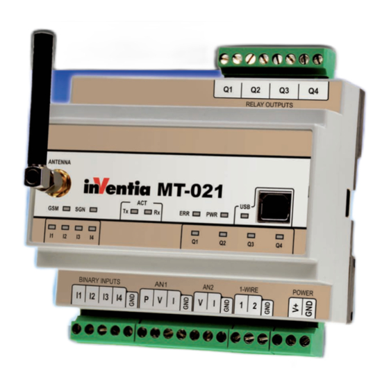
Page 15: Relay Outputs
These flags may be used in events table to trigger rules. 3.7.2. Relay outputs MT-021 telemetry module has 4 relay outputs Q1 ... Q4. Outputs can operate in one of two functional modes: monostable bistable The outputs operate independently and are isolated from each other. -
Page 16: Real Time Clock (Rtc)
20mA 3.7.4. Real time clock (RTC) MT-021 Module is equipped with astronomical time clock (RTC). The clock is a base for defining working cycles of module, timers and time stamps for measurement results recorded in registers. Imprecise clock setting results in faulty time stamping and subsequent loss of vital information. -
Page 17: Event Logger
3.7.8. 1-Wire inputs Telemetry Module MT-021 is equipped with two 1-Wire inputs for connection sensors using this interface for transmission of measured temperature value and Dallas I-button used for identification. - Page 18 15 ...
-
Page 19: Starting The Module
4. Starting the module Starting MT-021 module requires few basic activities. There are two methods of configuring module: locally - using MTManager remotely - via SMS Using one method does not exclude using of the second as the can be used interchangeably. -
Page 20: Configuring Mt-021 Using Mtmanager
Setting RTC clock of the device. 4.1. Configuring MT-021 using MTManager Install MTManager on your PC from CD provided with module. When installed with default setting MTManager creates shortcuts on Desktop and in Start menu. -
Page 21: Configuration Password
Choose MT-021 as type, type module name (e.g. ST_1) in name field and select firmware version (firmware version is marked on the box). In the next step set parameters essential for establishing GSM connection: SIM card PIN number (required if PIN code request is on ... - Page 22 Create Event EVT1 (in this example event will be triggered by binary input I1 when changing it will change logical state 0->1). As last step of configuration please set SMS sending rule 1. Choose EVT1 as Triggering event, type ALARM in text.
- Page 23 USB cable provided with module. Proper USB connection is signaled by USB LED. Operating system should automatically install driver for MT-021 - it will be seen in Device Manager as additional COM port called Silicon Labs CP210x USB to UART Bridge (COMX), where X is COM port number.
-
Page 24: Remote Configuration Via Sms
I1 and power GND with binary inputs GND, will result in sending SMS that reads ‘ALARM ‘ to +48111222333. 4.2. Remote configuration via SMS Configuration described in chapter Configurating MT-021 using MTManager can be also written to module using SMS commands. Those commands, their default values and allowed value ranges are described in chapter Appendices/Module configuration via SMS. -
Page 25: How Do Idisable Asim Pin Number
&#SPIN="2323"#CONF_PSW="PASS"#SMSN_1="+48111222333"#EVNO=1 #EV_TRIG_1=2#EV_FLAG_1=0#EV_EDGE_1=1#TRNO=1#TR_TRIG_1=1 #TR_TCH_1=1#TR_T_1="ALARM"#TR_N_1=1 That SMS sets: SIM card PIN number (2323) Configuration password (PASS) First telephone on Authorized->Phone list (+48111222333) Event EVT1 triggered when binary input I1 changes its logical state 0->1 SMS sending rule 1 which will send SMS saying ALARM to previously defined telephone number each time event EVT1 is triggered. -
Page 26: Connections Scheme
The chapter shows standard configurations securing proper operation of MT-021 module's integral inputs/outputs in all available operating modes. 5.1. Power supply MT-021 module can be powered from any DC power source providing voltage within the range 9-30 VDC. Notice! Exceeding the range of power supply may cause faulty... -
Page 27: Binary Inputs I1
5.2. Binary inputs I1 ... I4 Internal optoisolated binary inputs marked as I1...I4 may work only in positive logic. All binary inputs have same reference - module's electrical ground - negative pole of the power supply connected to GND pin. Connection scheme: Notice! Supply cables length <... -
Page 28: Relay Outputs Q1
5.3. Relay outputs Q1...Q4 Telemetry module has 4 normally open (NO) relay outputs marked as Q1 ... Q4. The outputs operate independently and are isolated from each other. Connection scheme: Notice! Maximum voltage between contacts is 230V AC Maximum switching current is 6A. 5.4. - Page 29 Pt-100 - 2 wire (AN1 only) Pt-100 - 3 wire (AN1 only) NTC (AN2 only) Voltage output sensor 26 ...
-
Page 30: 1-Wire Inputs
Current output sensor 5.5. 1-Wire inputs For the 1-Wire communication is used one line for data and GND line. The MT-021 has two 1-Wire bus inputs marked as 1 and 2 with a common reference point (GND). Connection scheme: 27 ... -
Page 31: Configuration
6. Configuration 6.1. General information The configuration of MT-021 module, as is the case for other modules in the MT series, is carried out using the MTM (MT Manager) program portal, delivered free of charge to users of our telemetry solutions. -
Page 32: Header
6.2.1. Header Header of parameter structure describes MT-021 telemetry module. It holds basic information unique to the module, the configuration contained by module and configuration file version. Information displayed is not user editable and solely used for verification and information purpose. -
Page 33: Modem's Firmware Version
6.2.1.6. Modem's firmware version Function - displays GSM modem's firmware version Data type - text Range - n/a, read-only parameter Default value - n/a Comments - the field updates automatically after downloading the firmware. 6.2.1.7. Firmware version Function - displays the identifier of current firmware version Data type - text Range... -
Page 34: Last Reading Time
6.2.1.11. Last reading time Function - displays internal module time recorded during last configuration reading or during last time setting Data type - text Range - compliant with Date and Time format Comments - this field is useful in verifying last access time and checking internal module clock settings (RTC) 6.2.2. -
Page 35: Sms
When GPRS is enabled new group of parameters called GPRS is visible. 6.2.3. SMS Group SMS contains parameters related to sending and receiving of text messages by MT-021 module. 6.2.3.1. Daily SMS limit Function Defines max number of SMS, the module may send during one day. - Page 36 All SMS messages are sent regardless of the GSM roaming Default value Answer Comments In order to be able to sent SMS in roaming the SIM card in the module has to have roaming option active. 6.2.3.3. Number of SMS sending retries Function Defines max number of retries of failed SMS transmission Data type...
-
Page 37: Formats
Comments The recipient must be previously defined in Authorized numbers -> Phone. 6.2.3.5.2. SMS limit exceed information Function Contains the text of the SMS message sent upon reaching Daily SMS limit. Data type Text Range max 160 characters Default value empty Comments This information is sent beyond standard messages queue and... - Page 38 HH - if placed in this format text automatically changed for current hour in 24h format (e.g. 01), MN - if placed in this format text automatically changed for current minutes (e.g. 01), SS - if placed in this format text automatically changed for current seconds (e.g.
-
Page 39: Symbolic Names
6.2.3.7.2. Symbolic name Function Defines user friendly name Data type Text Range 0..50 characters Default value IREG0...IREG15 Comments 6.2.3.7.3. Space Function Selection of register address space assigned to symbolic name. Data type selection list Range HReg Internal registers address space (registers readout) IReg Analog input address space (registers readout) -
Page 40: Macro Name
Default value Comments 6.2.3.8.2. Macro name Function Defines macro's user friendly name Data type Text Range 0..20 characters Default value Comments 6.2.3.8.3. Macro's content Function The content that is inserted into the SMS message, instead of macro name. Data type text Range 0..160... -
Page 41: Module Ip
Default value - empty Comments - Optional parameter used only if required by GSM network operator 6.2.4.4. Module IP Function - allows user to define IP number for newly created module definition and displays IP number read from the module configuration that was assigned to the module during last login to GPRS network Data type... -
Page 42: Authorized Numbers
whether transmission is still possible. The frame is sent to the address specified by parameter GPRS testing IP address, if different than 0.0.0.0. Lack of reply to sent ping frame after exercising defined timeout and number of retries is considered as GPRS connection loss and resets modem. -
Page 43: Phone
Data type selection list Range authorization is on authorization is off Default value Comments If set to Yes, all mobile phones stored on SIM card are treated as if they were placed on Authorized numbers\Phone list with tick next to Receiving voice calls option. -
Page 44: Terminals
Final functionality of each input depends on settings and configuration parameters connected. 6.2.6.1.1. Inputs I1 ... I4 Module MT-021 has four identical binary inputs. Inputs can operate in one of two functional modes: standard binary input ... -
Page 45: Triggering Slope
6.2.6.1.2. Outputs Q1 ... Q4 The MT-021 module is equipped in four relay outputs Q1...Q4. Outputs can operate in one of two functional modes: monostable bistable Each mode has a set of specific configuration parameters. -
Page 46: Name
6.2.6.1.2.1. Name Function Defines output's user friendly name Data type Text Range Letters and numerals, max 16 characters Default value Respectively (Q1...Q4) Comments Assigning friendly names facilitates discrimination of outputs destination and required settings. 6.2.6.1.2.2. Output mode Function selection of binary output mode Data type selection list Range... -
Page 47: Name
6.2.6.1.3. Analog inputs AN1...AN2 MT-021 module is equipped with two analog inputs operating in 4...20mA or 0...5V/0...10V standard and direct measurement of the temperature sensor PT100 (AN1) or NTC (AN2). Each mode has a set of specific configuration parameters. 6.2.6.1.3.1. Name... - Page 48 Range 0...10V or 0...5V Default value 0...10V Comments - N/A 6.2.6.1.3.5. Low reference - internal units Function - used along with other reference parameters for rescaling input signal range to engineering units range Data type - number Range 0...500 for voltage input (range 0...5V) 0...1 000 for voltage input (range 0...10V) 0...2 000 for current input Default value...
- Page 49 6.2.6.1.3.9. Alarm HiHi - engineering units Function - Defines HiHi alarm level for analog signal value in engineering units. Data type - number Range -32767...32767 Default value 32 767 Comments - Upon exceeding the preset value by analog signal the HiHi alarm flag is risen.
-
Page 50: Name
1 engineering unit. Deadband flags are dedicated to continuous monitoring of analog signal changes. 6.2.6.1.4. Inputs 1-WIRE1, 1-WIRE2 MT-021 module is equipped with two 1-WIRE inputs which allow connection of external transducers (e.g. temperature sensors). 6.2.6.1.4.1. Name Function... -
Page 51: Alarm Hihi
6.2.6.1.4.2.1.1. Alarm HiHi Function - Defines HiHi alarm level for 1-wire value. Data type - number Range -25...125 Default value Comments - Upon exceeding the preset value by 1-wire signal the HiHi alarm flag is risen. The resetting level of the flag depends on setting. -
Page 52: Deadband
6.2.6.1.4.2.1.6. Deadband Function - This parameter defines a minimal change of registered 1-wire signal to react on. Data type - number Range 0..50 Default value Comments - When set to value 0, the flag will rise upon every detected signal change by minimum 1 unit. Deadband flags are dedicated to continuous monitoring of 1-wire signal changes. -
Page 53: Period
6.2.6.3. State logging Save status Subgroup contains parameters for defining messages (which may include the current states of inputs and outputs) periodically saved in the event logger of MT-021 module. This allows to periodically record measured values. 6.2.6.3.1. Start [HH:MM] Function... -
Page 54: Logged Information
6.2.6.3.3. Logged information Function Defines text of message periodically put in event logger Data type text Range 0..160 characters Default value Comments text may contain any string of characters, except diacritical. It may contain mnemonics dynamically replaced at run-time by values drawn from the module e.g.: time, register or logical states of bits. -
Page 55: Trigger Input
Clocks Events associated with TMR1...TMR4 timer flags Flags Events generated by the system/internal processor Counters Events associated with counter's flags Connections Events associated with incoming telephone calls Default value None Comments 6.2.7.3.1. Trigger input Function select flag of binary input which can trigger an event Data type selection list Range... -
Page 56: Trigger Input
Default value None Comments 6.2.7.4.1. Trigger input Function select flag of analog input which can trigger event Data type selection list Range AN1, AN2 Default value Comments 6.2.7.4.2. Trigger condition Function Defines the alarm flag associated with the selected analog input and used to trigger an event Data type selection list Range... -
Page 57: Trigger Condition
Range 1-WIRE1...1-WIRE2 Default value 1-WIRE1 Comments 6.2.7.5.2. Trigger condition Function Defines the alarm flag associated with the selected 1-WIRE input and used to trigger an event Data type selection list Range Alarm HiHi, Alarm Hi, Alarm Lo, Alarm LoLo Default value Alarm HiHi Comments 6.2.7.6. -
Page 58: Triggering Flag
6.2.7.7. Trigger source (Flags) Function defines resource to trigger event Data type selection list Range None Inactive event Binary inputs Events associated with binary inputs I1 ... I4 Analog inputs Events associated with analog inputs AN1, AN2 Inputs 1-WIRE Events associated with 1-WIRE inputs Clocks Events associated with TMR1...TMR4 timer flags Flags... -
Page 59: Triggering Counter
Connections Events associated with incoming telephone calls Default value None Comments 6.2.7.8.1. Triggering counter Function Defines the flag associated with the configured counter input and used to trigger an event Data type selection list Range I1...I4 Default value Comments 6.2.7.9. Trigger source (Connections) Function defines resource to trigger event Data type... -
Page 60: Rules
Default value Comments 6.2.7.9.1.1. Dial-in from number Function select phone number name from authorized list which can trigger event Data type selection list Range friendly names of recipients associated with phone numbers in Authorized number list Default value NUM 1 - first number on the list Comments 6.2.8. -
Page 61: Smtp Authentication
6.2.8.1.3. SMTP server name Function Allows to enter name of SMTP server which will be used for e-mail sending, e.g. smtp.company.com Data type text Range 0..31 characters Default value Comments 6.2.8.1.4. SMTP server port Function declares port number which is used for communication with SMTP server Data type number... -
Page 62: Triggering Event
Default value Comments 6.2.8.1.8. Message sending rules 1...32 Each of rules residing on the list is defined by following parameters: Triggering event Transmission type Recipient number Receiver e-mail address E-mail title Message text 6.2.8.1.8.1. Triggering event Function Assigns which one of previously defined event will trigger sending of a particular text message. -
Page 63: Clip Calls
6.2.8.1.8.4. Receiver e-mail address Function Allows to enter receiver e-mail address, e.g. jane.brown@other_company.com Data type text Range 0..31 characters Default value Comments 6.2.8.1.8.5. E-mail title Function Defines an e-mail title Data type text Range 0..31 characters Default value Comments 6.2.8.1.8.6. Message text Function Defines text which will be send as an e-mail or SMS message... -
Page 64: Recipient Number
6.2.8.2.1. Number of CLIP calls rules Function declares number of CLIP calls rules. Data type number Range 1..16 Default value Comments diminishing the number of rules does not delete settings until the configuration is written to the module. 6.2.8.2.2. CLIP call rules 1...16 Each of rules residing on the list is defined by following parameters: Triggering event Recipient number... -
Page 65: Smtp Authentication
Default value Comments diminishing the number of rules does not delete settings until the configuration is written to the module. 6.2.8.3.2. Sender e-mail address Function Allows to enter sender e-mail address, e.g. john.smith@company.com Data type text Range 0..31 characters Default value Comments 6.2.8.3.3. -
Page 66: Smtp Password
6.2.8.3.6. SMTP user name Function Allows to enter user name which will be used during authentication process on SMTP server, e.g. john.smith Data type text Range 0..31 characters Default value Comments 6.2.8.3.7. SMTP password Function Allows to enter password which will be used during authentication process on SMTP server, e.g. -
Page 67: Configuration Writing
6.2.8.3.8.3. E-mail title Function Defines an e-mail title Data type text Range 0..31 characters Default value Comments 6.2.8.3.8.4. E-mail text Function Defines text of an message Data type text Range 0..160 characters Default value Comments Text may contain any string of characters, except diacritical signs. -
Page 68: Technical Data
Current for 24 VDC Max 0,70 CAUTION! Due to high momentary current consumption the power supply must be capable of delivering >= 1A of current. Inappropriate power supply may result in faulty operation or cause damage to MT-021 module! 65 ... -
Page 69: An1, An2
7.4. Binary inputs I1..I4 Signal voltage range 0 ... 30VDC Input resistance 5,4 k Input ON (1) voltage > 9V Input OFF (0) voltage 0 ... 3V 7.5. Relay outputs Q1...Q4 Output type Relay, optoisolated, NO Maximum voltage between contacts 250VAC/300VDC Load current 6A/230VAC, 6A/24VDC... -
Page 70: Drawings And Dimensions
7.7. Drawings and dimensions (All dimensions in millimeters) 67 ... -
Page 71: Problem Solving
8. Problem solving 8.1. LED signaling LED indicators placed on MT-021 panel are a great diagnostic tool. In table below are described all states signaled by LED diodes. Signaling Description Module powered V+ and GND terminals USB connected - module powered from USB Input activated I1...I4... -
Page 72: Sim Card
8.2. Unblocking of SIM card Three failed attempts of entering PIN code locks the SIM card and requires entering the PUK code. The fact that the SIM card locked is indicated by the ERR LED. An attempt to unlock the module may be performed only when the right PIN code is known. Necessary procedure: ... -
Page 73: Explosive Environment
When there is a need of installing telemetry module in vicinity of medical equipment one has to contact the manufacturer of this equipment in order to make sure that the equipment is adequately protected against interference of radio frequency waves (RF). 9.2.4. - Page 74 10.2. Module configuration via SMS MT-021 can be configured locally using MTManager (software tool for telemetry modules management) and remotely via SMS commands. However, you should note that the first SMS message with configuration commands is processed without sender authorization verification - number of sender does not have to figure on Authorized numbers->Phone...
- Page 75 General group: Parameter MTManager description Default value Range Definition from 4 to 8 SPIN SIM card PIN number empty characters or empty CONF_PSW Configuration password empty max. 32 characters 2000-01-01 YYYY-MM-DD CRTC RTC time 00:00:01 HH:MN:SS GPRS_EN Use of GPRS SMS group: * - index from 1 to 16 Default...
- Page 76 Authorized numbers group: * - index from 1 to 32 Default Parameter MTManager description Range Definition value LPHN Number of phone numbers 1...32 Update phone numbers from SIM SPBS card Phone number from SIM card SALS always authorized SMST_* Name NUM * max.
- Page 77 Default Parameter MTManager description Range Definition value None EVT1 OUT_OFFEVT_* Off event EVT16 (* - index from 1 to 16) Analog inputs AN1, AN2 * - index from 1 to 2 AN_NAME_* Name max. 16 characters Voltage input Current input AN_MODE_* Input type PT100 (AN1) or...
- Page 78 Synchronous timers TMR1...TMR4 group: * - index from 1 to 4 Default Parameter MTManager description Range Definition value TMR_ON_* Active TMR_START_* Start [HH:MM] 00:00 00:00...23:59 1 min. 2 min. 3 min. 5 min. 10 min. 15 min. 30 min. TMR_PERIOD_* Period 1 hour.
- Page 79 Events group: † - index from 1 to 16 Default Parameter MTManager description Range Definition value EVNO Number of events 0...32 None Binary inputs Analog inputs Inputs 1-wire EV_TRIG_† Trigger source Clocks Flags Counters Connections Binary inputs I1...I4 (counter inputs) EV_FLAG_†...
- Page 80 Rules group: * - index from 1 to 16 † - index from 1 to 32 Default Parameter MTManager description Range Definition value Message sending TRNO Number of message sending rules 1...32 TR_SMF Sender e-mail address empty max. 63 characters TR_SMA SMTP server name empty...
- Page 81 For example to enable authorization for eighth and ninth phone on the list you need to set parameter to 80010000 (10000000 00000001 00000000 00000000 in binary notation). 2.) Information about days of month is stored in one 32-bit digit, in which each single bit corresponds to one day of month according to table below: position Day of...
-
Page 82: Sms Mode
&ADMIN#LPHN=6#SMST_6="Mark"#SMSN_6="+48987654321" Module response: >#LPHN=6#SMST_6="Mark"#SMSN_6="+48987654321" Setting HiHi alarm threshold of 1-Wire 2 input to 115: &ADMIN#OW_ACT_2=2#OW_ALM_HH_2=115 Module response: >#OW_ACT_2=2#OW_ALM_HH_2=115 Setting new event on seventh position on event list. Event is triggered by crossing LoLo alarm threshold on analog input AN2: &ADMIN#EVNO=7#EV_TRIG_7=3#EV_FLAG_7=71#EV_EDGE_7=4 Module response: >#EVNO=7#EV_TRIG_7=3#EV_FLAG_7=71#EV_EDGE_7=4... - Page 83 After reception of SMS message, internal application tries to parse SMS text and execute command enclosed in it. Parsing process generates new message text, which is send back to user (if module is allowed to, either by configuration or by presence/absence of '$' sign).
- Page 84 causes module to write value 1234 to holding register 10 and send back SMS with text: >1234 Both read and write commands can be expanded by adding a prefix, which defines data format (notation). Prefix should be placed between '#' mark (command start) and register symbol, and should contain one (or more) characters ended with a dot.
- Page 85 #date #time: inputs - #B8.IB64, #IR19 SMS sent but expansion of macro 1 will not contain text assigned to macro name *mtime, therefore text being executed after macro 1 was used will look like: *mtime: input 0 counter: #D2.HR0 which in turn causes module to send back SMS containing: >*mtime: input 0 counter: 123 Register spaces Module's firmware distinguishes two register spaces:...
- Page 86 UTC time fetched from three consecutive registers Rn:Rn+1:Rn+2, where n corresponds to register symbol used. Time format according to „Time format” string in configuration. Local date fetched from three consecutive registers Rn:Rn+1:Rn+2, where n corresponds to register symbol used. Date format according to „Date format”...
- Page 87 Predefined symbolic names Name Description Returns local time read from RTC registers – the same as #LT.IR0 TIME command Returns local date read from RTC registers – the same as #LD.IR0 DATE command Returns UTC time and date read from RTC registers – the same as #T1.IR0 command NAME Returns module name...
-
Page 88: Memory Map
Binary representation of input register 4 (readout): #B.IR4 Read flag (bit) 4: #B.IB4 Write hexadecimal value 01AC to holding register 0: #H.HR0=01AC 10.4. Memory map All accessible from remote resources of MT-021 module were collected in two address spaces: analog inputs and internal registers. 85 ... - Page 89 10.4.1. Analog inputs address space Address 11 12 13 14 Description address Month Year Hour Day of month Seconds Minutes Event source Number of event in a second digital I/Os GSM status GSM signal GSM signal [0...31] Number of SMS messages sent since power Number of SMS messages sent today Number of SMS messages which could not been sent...
- Page 90 Address 11 12 13 14 Description address Pulse counters flags I4 CNT Timer flags TMR2 TMR3 TMR4 General flags: CALL * RESET - set to '1' after reset AUTH ORIZE * CALL AUTHORIZED - set to '1' on incoming authorized call Analog inputs alarm flags HiHi LoLo...
- Page 91 Address 11 12 13 14 Description address Number of e-mail sending errors (zeroed on reset) Number of e-mail sending retries (zeroed on reset) 88 ...
- Page 92 "GSM Status" register flags description Flag Description Modem OK Successful modem initialization GSM SEARCH GSM network searching GSM OK Module registered in GSM network GSM ERROR Unsuccessful GSM registration attempt SMS ERR Unsuccessful SMS sending attempt NO SIM No SIM card, or SIM card inserted improperly PIN ERROR Wrong PIN PIN CNT...
- Page 93 10.4.2. Internal registers address space Internal registers address space (read 03H/write 06H or 10) - Not zeroed at reset LOW byte HIGH byte Address addr Description Symbol Dec (Hex) 0 (0x00) 32 bit (Low 16 bits) counter - CNT_I1 input I1 1 (0x01) (High 16 bits) 2 (0x02)
-
Page 94: Flags
10.5. Flags During operation MT-021 module governs a number of binary flags (assuming value True or False) that trigger rules processing and remote diagnostics. The User has access to following flags: Bit name Description I1…I4 State of binary inputs I1...I4...
Need help?
Do you have a question about the MT-021 and is the answer not in the manual?
Questions and answers