
Subscribe to Our Youtube Channel
Related Manuals for INVENTIA MT-703


Summary of Contents for INVENTIA MT-703
- Page 1 T e l e me t r y M o d u l e T e l e me t r y M o d u l e M T - 7 0 3 M T - 7 0 3 U s e r M a n u a l t e l e me t r i a p l...
- Page 2 1471 Telemetry Module MT-703 User Manual GSM/GPRS Telemetry Module for monitoring and control Class 1 Telecommunications Terminal Equipment for GSM 850/900/1800/1900 v5.08 INVENTIA Sp. z o.o...
- Page 3 MT-703 © 2010 Inventia Ltd. Wszelkie prawa zastrzeżone. Żaden fragment niniejszego dokumentu nie może być powielany lub kopiowany w żadnej formie bez względu na stosowaną technologię – graficzną, elektroniczną lub mechaniczną, włączając fotokopiowanie i/lub zapis cyfrowy, również w systemach przechowywania i wyszukiwania dokumentów – bez pisemnej zgody Wydawcy.
-
Page 4: Table Of Contents
INDEX 1. DESIGNATION OF THE MODULE .......................... 4 2. GSM REQUIREMENTS ............................ 5 3. DESIGN OF THE MODULE ............................ 5 3.1. MT‐703 ............................ 5 AYOUT OF ELEMENTS 3.2. ................................ 5 HE RESOURCES 3.2.1. Binary inputs .............................. 6 3.2.2. Analog inputs .............................. 7 3.2.3. Timers ................................ 7 3.2.4. The internal logger ............................ 8 3.2.5. Real time clock .............................. 8 3.3. ................................ 9 ... - Page 5 6.1.2.7. USB mode ................................... 2 3 6.1.2.8. Low battery voltage alarm ............................ 2 4 6.1.3. The GPRS group .............................. 24 6.1.3.1. APN name .................................. 2 4 6.1.3.2. APN user name ................................ 2 4 6.1.3.3. APN login password .............................. 2 4 6.1.3.4. IP assignment ................................ 2 5 6.1.3.5. Device's identifier ............................... 2 5 6.1.3.6. Module IP ................................... 2 5 ...
- Page 6 6.1.6. The Rules group .............................. 37 6.1.6.1. SMS sending ................................ 3 7 6.1.6.1.1. Number of SMS sending rules .......................... 3 7 6.1.6.1.2. SMS sending ............................... 3 8 6.1.6.1.2.1. Trigger source ............................. 3 8 6.1.6.1.2.2. Trigger flag .............................. 3 8 6.1.6.1.2.3. SMS message text ............................ 3 9 6.1.6.1.2.4. Recipient number ............................ 3 9 ...
-
Page 7: Designation Of The Module
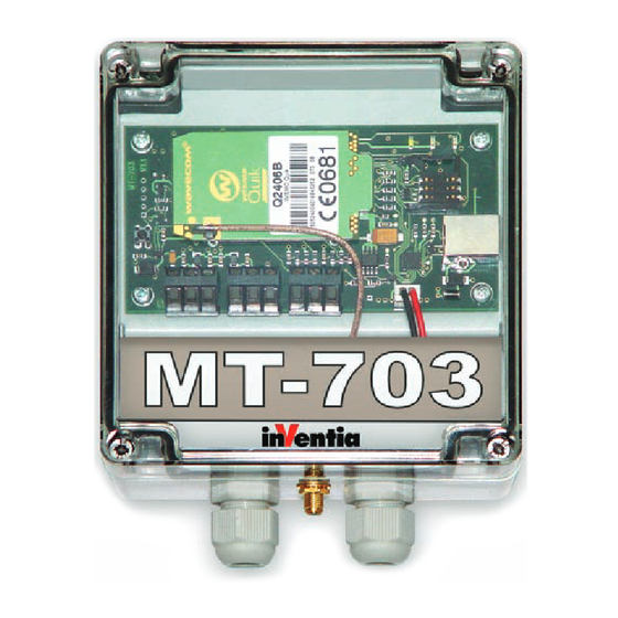
1. Designation of the module The MT-703 (or MT-703 HC) module is a specialized telemetry device. It is optimised for use in the simple measuring or alarm systems, which do not have network power supply. The module features compact design and low energy consumption from integrated batteries. -
Page 8: Gsm Requirements
3. Design of the module 3.1. Layout of MT-703 elements 3.2. The resources Hardware resources of the MT-703 module: DI - binary with counting and powering of potential-free contact capabilities inputs with alarm on opening the module cover AI - analog 0-3.3 VDC, with option of powering the measured circuit... -
Page 9: Binary Inputs
3.2.1. Binary inputs The MT-703 telemetry module has two general purpose binary inputs (DI) indicated as I1, I2, and one auxiliary binary input I3, which is factory connected with the cover opening sensor. Because the operation of the I3 input is factory fixed and it has no additional features we focus on the functionality of the inputs I1, I2 only. -
Page 10: Analog Inputs
The mode of input operation depends on its configuration. 3.2.2. Analog inputs The MT-703 telemetry module has two analog inputs (AI) of voltage type marked as AN1, AN2. The inputs operate in 0 - 3.3 VDC voltage range. They convert an analog signal from sensors powered by the 3.3 VDC voltages. -
Page 11: The Internal Logger
3.2.4. The internal logger The MT-703 telemetry module is equipped with programmable logger which can collect up to 576 data records. This allows to store the 24 hours measurements, executed every 5 minutes. -
Page 12: Usb Interface
3.3. USB interface The USB interface built inside the MT-703 module is used for the connecting a computer during the local configuration of the module. Because the USB standard provides a possibility of powering the devices connected to the USB port from the host computer, such mode is also possible in this particular case. -
Page 13: Powering Of The Module
3.4. Powering of the module The MT-703 telemetry module can be powered only from the built-in set of batteries of nominal voltage 4.5 VDC. The batteries are placed inside the special holder under the main circuit board of the module. They are connected to the board by two-wire cable with a miniature plug. -
Page 14: Leds
3.6. LEDs The LEDs placed on the MT-703 module board simplify the running process of the module. The LEDs have strictly assigned meanings: The GSM LED indicates the operation mode of the GSM module. The Status LED indicates activity and stand-by states of the GSM module. -
Page 15: The Antenna
I2 are initialized to "0" (cleared). 3.9. The antenna Connecting the antenna is necessary to provide the proper operation of the MT-703 telemetry module. The antenna should be connected to the SMA (or optionally FME) socket placed on the bottom side of a module housing. -
Page 16: Connecting The Module
The potential on the opened binary inputs is not greater than 2.5 VDC. 4.2. Connecting the analog inputs A1, A2 The analog inputs of the MT-703 module are the voltage type, with the input voltage range from 0 to 3.3 VDC. -
Page 17: Connecting Supply Voltage
MT-703 module). 4.3. Connecting supply voltage The MT-703 module is powered by the internal 4.5 VDC battery, consisting of 3 pieces of 1.5 V R20 alkaline cells (6 pieces in HC version). The total capacity of a new battery set is estimated as 16 Ah (32 Ah for HC). Depending on the data or SMS transmission events rate, it allows for an autonomous operation of the module without replacing the battery even up to 5 years. -
Page 18: Running The Module
5.2. Initial setup During the initial setup of the MT-703 module the parameters ensuring login onto GSM network and/or GPRS transmission are configured. To make this configuration properly, the module must be connected by an USB cable with the PC, which runs the MTM program. -
Page 19: Inserting Sim Card
GPRS packet data transmission. It is recommended to insert a SIM card while a supply voltage is off, so in the case of the MT-703 module means not only disconnecting battery and USB cable but also waiting a time till the module is not active anymore. The SIM card can be placed in a holder before the initial setup is done. -
Page 20: Starting The Module
1. No communication with the GSM modem 2. The GSM modem is running 3. The USB port of the MT-703 module is ready for communication 4. The GSM modem is registered in the GSM network 5. The GSM modem is logged in the selected APN of GPRS network ... - Page 21 The blink repetition period and blinks duration are shown on the figure below. In a case of problems with the network registration you should observe the Status LED. During the login operation the Status LED shows the strength of GSM signal passing from the antenna to the module, in a scale 1...5.
-
Page 22: Configuration
6. Configuration The configuration of the MT-703 module is accomplished by means of MTManager software (MTM). This software package is distributed free of charge to the users of our telemetric equipment. The MTManager is a programmatic environment designed especially for managing the entire telemetric system despite of its size. -
Page 23: Module Type
This field contains unique and fixed serial number of the device and is used as the module identifier. It is originally assigned to the module by the manufacturer. 6.1.1.5. Module firmware version Function Identifier of current firmware version of the MT-703 telemetry module Data type Text Variation... -
Page 24: Last Configuration Date
6.1.1.8. Last configuration date Function Date and time of the last effective update of the module configuration Data type Text Variation None, read-only parameter range Comment This value changes automatically after the successful storing of configuration. It can be used for tracing of non-authorized configuration changes 6.1.1.9. -
Page 25: Gsm Band
6.1.2.2. GSM band Function sets the frequency of locally-employed GSM system. Data type selection list List EU-900/1800 MHz for areas employing 900/1800 MHz standard US-850/1900 MHz for areas employing 850/1900 MHz standard Default EU-900/1800 MHz value Comments Parameter active only in modules using quad-band Wavecom WISMO Quick PLUS modem module. -
Page 26: Monthly Sms Limit
Variation range The module operates in the GPRS mode, and attempts login to the selected APN after switching on. It is obligatory to use the SIM card in this mode because it enables access to the GPRS The module operates in GSM mode. The only way of remote communication is SMS messaging. - Page 27 6.1.2.8. Low battery voltage alarm Function Sets alarm level for the module supply voltage Data type Number Variation 0.01…100.00 range Default Standard value Associated Bat_Low flag Comment Setting the flag on low battery voltage alarm is important, because the battery is the only one available power source for the module. Normally it is hard to precisely define the remaining battery capacity and its usability time, so this flag may be useful 6.1.3.
-
Page 28: Ip Assignment
6.1.3.4. IP assignment Function Selects the way of the IP assignment while login the module to GPRS network Data type Selection list Variation Static range Optimum mode for the transmission with static addressing, when the module obtains the same IP address with each login to the network Dynamic The alternative mode for static addressing. -
Page 29: Spooler
IP address of the computer which runs MTSpooler (i.e., the program for automated update of the module configuration). After login to the network the MT-703 module sends the information about its readiness for a configuration update to the entered IP... -
Page 30: Number Of Login Retries
Comments This parameter sets recipient's address for data frames testing GPRS transmission channel sent after 4 minute elapses. Leaving recipient address at 0.0.0.0 sends data frames to module's own IP address. Any other valid address (within the APN) is accepted as the recipient. -
Page 31: The Authorized Numbers Group
6.1.4. The Authorized numbers group The Authorized Numbers group contains the lists of phone numbers and IP addresses which the module will communicate with. The IP address list is also used as the base for defining access to the configuration changes and data receiving. 6.1.4.1. -
Page 32: Resources
6.1.5.1.1. Binary inputs I1, I2 The MT-703 module has two identical binary inputs. An energy saving feature of the module assumes these inputs should be connected with potential-free contacts. Such contacts are placed between the input and the module ground terminal. -
Page 33: Module Activation
6.1.5.1.1.3. Module activation Function - Defines the method of the module activation Data type - Selection list Variation range The binary input state change causes the module activation and starts the processing of rules The function is disabled Default value Comment - Setting this parameter to causes asynchronous and... - Page 34 6.1.5.1.2. Binary input I3 The MT-703 module has a special binary input I3, which is factory connected with a cover opening sensor. Activating this sensor causes immediate wake up of the module, and then the information about the cover opening may be sent out. The information may contain data packet or it may be a SMS message.
-
Page 35: Low Reference - Internal Units
6.1.5.1.3. Analog inputs AN1, AN2 The MT-703 module has two identical analog inputs. Each analog input is associated with the output of a supply voltage used for powering the analog signal sensor. Such solution allows to minimize the energy consumption comparing to continuous powering of a sensor. -
Page 36: High Reference - Engineering Units
range Default value Comment - Together with remaining reference parameters, this one is used to transform the physical input signal range to the range expressed in engineering units 6.1.5.1.3.4. High reference - engineering units Function - The high reference level for engineering units Data type - Number Variation... -
Page 37: Alarm Lolo
Comment - Sets the flag used in rules processing 6.1.5.1.3.8. Alarm Lo Function - The Lo alarm level for the signal on the analog input, expressed in engineering units Data type - Number Variation - 0…10000 range Default value Comment - Sets the flag used in rules processing 6.1.5.1.3.9. -
Page 38: Measure Timer (T1)
range Default - 00:00 value Comment - This parameter sets the point on the 24-hours time scale which is then used as the reference for the moments when measurements and data transmissions begin 6.1.5.2.2. Measure timer (T1) The Measure timer is responsible for periodic activation of the module in order to make the signal measurements, to compute the signal increments, to check the alarm levels and then to process the rules. -
Page 39: Logger
6.1.5.3. Logger 6.1.5.3.1. Activity Function - Selects an activity of the data logger Data type - Selection list Variation range The data logger is enabled The data logger is disabled Default value Comment - n/a 6.1.5.3.2. Write timer Function - Selects the timer which will initialize the process of writing data to the logger Data type - Selection list... -
Page 40: The Rules Group
The parameter list contains all parameters which can be used to create the Status. Selected variables should be marked on the list. 6.1.6. The Rules group The Rules group contains lists of transmission tasks which are to be executed by module firmware according to the rule criteria. -
Page 41: Sms Sending
6.1.6.1.2. SMS sending Each rule on the list is defined by the following parameters: Trigger source Trigger flag SMS message text Recipient number Status sending 6.1.6.1.2.1. Trigger source Function - Selects the source of event which can trigger the rule Data type - Selection list Variation... -
Page 42: Data Sending
6.1.6.1.2.3. SMS message text Function - The text of the message to be sent when the rule is triggered Data type - Text Variation - Letters, digits and special characters - maximum length is range 160 characters Default value Comment - Total length of the SMS message text together with status information is limited to 160 characters. -
Page 43: Number Of Data Transmission Rules
The number of rules can be set by the value of Number of data sending rules parameter as well. 6.1.6.2.1. Number of data transmission rules Function - Number of rules used for data sending Data type - Number Variation - 1…32 range Default value Comment... -
Page 44: Ip Address
6.1.6.2.2.2. Trigger flag Function - Defines the flag associated with the selected input and used to trigger an event Data type - Selection list Variation None range The rule is disabled Bi In 0->1, Bi In 1->0 The flags which are to be set by the binary input state change Min DTA, Max DTA The flags which are to be set by a low and a high... -
Page 45: Counters
In the MT-703 module there are the values of counters associated with binary inputs I1 and I2. 6.2.1. Counters In the MT-703 module the initial setup is allowed only for two resources, namely the counters associated with binary inputs I1 and I2. Resource name... -
Page 46: Verifying The Configuration
7. Troubleshooting 7.1. LED signaling The tree LEDs placed on the circuit board of the MT-703 module are a very useful diagnostic tool. As it was mentioned previously, each LED has a specific function and its name. Starting from the left, there are following diodes: ... - Page 47 5. The GSM modem is logged in the selected APN of GPRS network The blink repetition period and blinks duration are shown on the figure below. The above sequence of blinks is valid only with successful login onto the GSM/GPRS network.
-
Page 48: Unlocking The Sim Card
The above described procedures will reset the counter of faulty attempts stored in the SIM card and will enable the access to the card from the MT-703 module. An additional possibility of SIM card unlocking is provided by connecting the module to the PC and use a terminal emulation program (for example Hyperterminal). -
Page 49: Replacing The Battery
7.3. Replacing the battery Despite the large capacity of batteries powering the MT-703 module, sometimes it may be necessary to replace them with the new ones. It is quite easy and does not require special preparations due to a special mechanical construction of the module. To replace the battery you should: ... -
Page 50: Gsm/Gprs Modem
8.2. GSM/GPRS modem WISMO Quick 2406B: Modem type WISMO Quick 2406B Dual Band GSM/GPRS module EGSM900/1800 Frequency range Transceiver: from 880 MHz to 915 MHz (EGSM 900 MHz) Receiver: from 925 MHz to 960 MHz Peak transmitting power 33 dBm (2W) – class 4 station (EGSM 900 MHz) Frequency range Transceiver: from 1710 MHz to 1785 MHz... -
Page 51: Power Supply Output For Analog Sensor
8.4. Power supply output for analog sensor Output voltage 3.3 V Maximum output current 150 mA Minimum activity period 50 s 120 s Maximum activity period 300 s (active connection with spooler or logger data transmission) Voltage settling time (before the 40 s measurement) 8.5. -
Page 52: Drawings And Dimensions (All Dimensions Are In Millimeters.)
8.8. Drawings and dimensions (All dimensions are in millimeters.) MT-703 module (standard version) MT-703 module (HC version) 49 ... -
Page 53: Safety Informations
9. Safety informations 9.1. Working environment When deploying telemetry modules one has to observe and comply to local legislation and regulations. Using the telemetry module in places where it can cause radio noise or other disturbances is strictly prohibited. 9.2. Electronic equipment Thou most of modern electrical equipment is well RF (Radio Frequency) shielded there is no certainty that radio waves emitted by the telemetry module's antenna may have negative influence on its function. -
Page 54: Appendices
10.2. Triggering inputs During operation, the internal system of MT-703 module creates a number of variables related to its inputs/outputs and to module diagnostics. Triggering inputs and triggering flags in conjunction with rules processing enable instantaneous reaction in occurring states. -
Page 55: Memory Map
10.3. Memory map Internal registers (read 3) Description Write 15 14 13 12 11 10 Binary inputs IxRE - rising edge 0x04 I3FE I2FE I1FE I3RE I2RE I1RE I3 I2 I1 flag IxFE - falling edge flag Binary outputs (not implemented) 0x05 Counter I1 0x06... -
Page 56: Flags
10.4. Flags During the operation, the inner system of the MT-703 module sets several binary flags (with the values True or False), which enable the triggering of rules and the remote diagnostics of the module. There are following flags available for the user:... -
Page 57: Housing 121207/121210 - Technical Specification
10.5. Housing 121207/121210 - technical specification 54 ...
Need help?
Do you have a question about the MT-703 and is the answer not in the manual?
Questions and answers