
Subscribe to Our Youtube Channel
Related Manuals for BOC Starpower 304


Summary of Contents for BOC Starpower 304
- Page 1 OM 2208 175 493L October 1999 Processes Multiprocess Welding Description Arc Welding Power Source Starpower 304 CC/CV and CC Models...
-
Page 3: Table Of Contents
TABLE OF CONTENTS SECTION 1 – SAFETY PRECAUTIONS - READ BEFORE USING ......1-1. -
Page 5: Section 1 - Safety Precautions - Read Before Using
SECTION 1 – SAFETY PRECAUTIONS - READ BEFORE USING som _nd_4/98 1-1. Symbol Usage Means Warning! Watch Out! There are possible hazards with this procedure! The possible hazards are shown in the adjoining symbols. This group of symbols means Warning! Watch Out! possible Y Marks a special safety message. - Page 6 ARC RAYS can burn eyes and skin. BUILDUP OF GAS can injure or kill. D Shut off shielding gas supply when not in use. Arc rays from the welding process produce intense D Always ventilate confined spaces or use visible and invisible (ultraviolet and infrared) rays that can burn eyes and skin.
-
Page 7: Additional Symbols For Installation, Operation, And Maintenance
1-3. Additional Symbols For Installation, Operation, And Maintenance FIRE OR EXPLOSION hazard. MOVING PARTS can cause injury. D Do not install or place unit on, over, or near D Keep away from moving parts such as fans. combustible surfaces. D Keep all doors, panels, covers, and guards D Do not install unit near flammables. -
Page 8: Emf Information
1-5. EMF Information Considerations About Welding And The Effects Of Low Frequency 1. Keep cables close together by twisting or taping them. Electric And Magnetic Fields 2. Arrange cables to one side and away from the operator. Welding current, as it flows through welding cables, will cause electro- magnetic fields. -
Page 9: Section 1. Consignes De Securite - Lire Avant Utilisation
SECTION 1 – CONSIGNES DE SECURITE – LIRE AVANT UTILISATION som _nd_fre 4/98 1-1. Signification des symboles Signifie Mise en garde ! Soyez vigilant ! Cette procédure présente des risques de danger ! Ceux-ci sont identifiés par des symboles adjacents aux directives. Ce groupe de symboles signifie Mise en garde ! Soyez vigilant ! Il y a des Y Identifie un message de sécurité... - Page 10 LES RAYONS DE L’ARC peuvent pro- LES ACCUMULATIONS DE GAZ ris- voquer des brûlures dans les yeux et quent de provoquer des blessures ou sur la peau. même la mort. Le rayonnement de l’arc du procédé de soudage D Fermer l’alimentation du gaz protecteur en cas de génère des rayons visibles et invisibles intenses non utilisation.
-
Page 11: Dangers Supplémentaires En Relation Avec L'installation, Le Fonctionnement Et La Maintenance
1-3. Dangers supplémentaires en relation avec l’installation, le fonctionnement et la maintenance Risque D’INCENDIE OU DES ORGANES MOBILES peuvent D’EXPLOSION. provoquer des blessures. D Ne pas placer l’appareil sur, au-dessus ou à proxi- D Rester à l’écart des organes mobiles comme le mité... -
Page 12: Principales Normes De Sécurité
1-4. Principales normes de sécurité Safety in Welding and Cutting, norme ANSI Z49.1, de l’American Wel- Safe Handling of Compressed Gases in Cylinders, CGA Pamphlet P-1, ding Society, 550 N.W. Lejeune Rd, Miami FL 33126 de la Compressed Gas Association, 1235 Jefferson Davis Highway, Suite 501, Arlington, VA 22202. -
Page 13: Section 2 - Introduction
SECTION 2 – INTRODUCTION 2-1. Specifications RMS Amps Input at Rated Load Output, 60 Hz 3-Phase at NEMA Load Voltage Amperage Max. Open- Voltages and Class I Rating Rated Output at Range in Range in Circuit 60% Duty Cycle 230 V 460 V 575 V CV Mode... -
Page 14: Volt-Ampere Curves
2-3. Volt-Ampere Curves Volt-ampere curves show mini- mum and maximum voltage and A. CC Mode amperage output capabilities of unit. Curves of other settings fall be- tween curves shown. ARC CONTROL B. CV Mode va_curve1 4/95 – SA-178 652 / SA-178 653 OM-2208 Page 10... -
Page 15: Section 3 - Installation
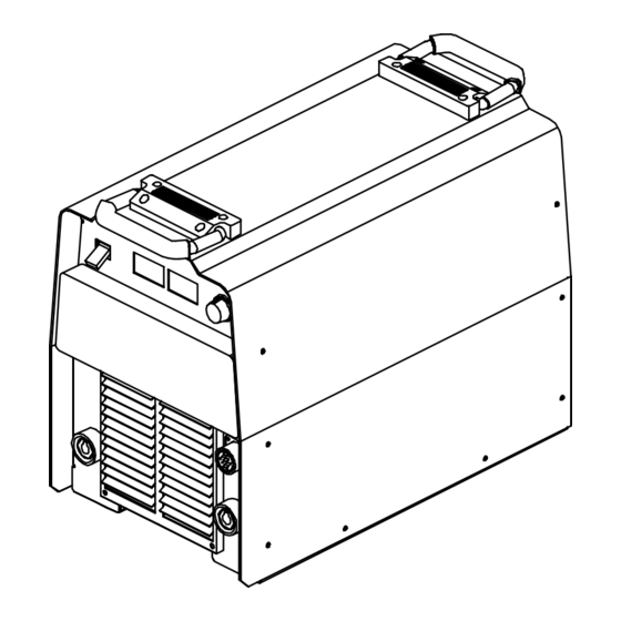
SECTION 3 – INSTALLATION 3-1. Selecting a Location 24 in (610 mm) Dimensions And Weight 76 lb (34.6 kg) 17 in (432 mm) 12-1/2 in (318 mm) Lifting Handles Movement Use handles to lift unit. Hand Cart Y Do not move or operate unit Use cart or similar device to move where it could tip. -
Page 16: Weld Output Receptacles And Selecting Cable Sizes
3-2. Weld Output Receptacles And Selecting Cable Sizes Total Cable (Copper) Length In Weld Circuit Not Exceeding 150 ft 200 ft 250 ft 300 ft 350 ft 400 ft 100 ft (30 m) Or Less (45 m) (60 m) (70 m) (90 m) (105 m) (120 m) -
Page 17: Optional 115 Volts Ac Duplex Receptacle And Circuit Breakers
3-4. Optional 115 Volts AC Duplex Receptacle And Circuit Breakers 115 V 10 A AC Receptacle Power is shared between duplex receptacle and Remote 14 recep- tacle (see Section 3-3). Circuit Breaker CB1 Circuit Breaker CB2 CB1 protects duplex receptacle and 115 volts ac portion of Remote 14 receptacle from overload. -
Page 18: Connecting Input Power
3-6. Connecting Input Power Check input voltage available at site. The Auto-Link circuitry in this unit automatically links the power source to the primary voltage being applied. 230/460 unit can be connected to either 230 or 460 VAC input power. A 460/575 model can be connected to either 460 or 575 VAC input power. -
Page 19: Section 4 - Operation
SECTION 4 – OPERATION 4-1. Front Panel Controls For CC/CV Model Power Switch best results, place Inductance/Dig control in wards minimum, short-circuit amperage at the maximum position. low arc voltage is the same as normal weld- The fan motor is thermostatically ing amperage. -
Page 20: Front Panel Controls For Cc Model
4-2. Front Panel Controls For CC Model Power Switch V/A Control switch. Dig Control For Air Carbon Arc (CAC-A) cutting and The fan motor is thermostatically When set towards minimum, short-circuit gouging, place switch in one of the Stick amperage at low arc voltage is the same as controlled and only runs when cooling is positions. -
Page 21: Meter Functions For Cc/Cv Model
4-3. Meter Functions For CC/CV Model NOTE The meters display the actual weld output values for approximately three seconds after the arc is broken. Mode Meter Reading At Idle Meter Reading While Welding Scratch 80.0 10.3 Start TIG Actual Volts (OCV) Preset Amps Actual Volts Actual Amps... -
Page 22: Meter Functions For Cc Model
4-5. Meter Functions For CC Model NOTE The meters display the actual weld output values for approximately three seconds after the arc is broken. Mode Meter Reading At Idle Meter Reading While Welding Scratch 80.0 10.3 Start TIG Actual Volts (OCV) Preset Amps Actual Volts Actual Amps... -
Page 23: Lift-Arc Tig Procedure
4-7. Lift-Arc TIG Procedure With Process Switch in the Lift-Arc TIG position, start an arc as follows: TIG Electrode Workpiece Touch tungsten electrode to work- piece at weld start point, hold electrode to workpiece for 1-2 seconds, and slowly lift electrode. An arc will form when electrode is lifted. -
Page 24: Voltmeter/Ammeter Help Displays
5-2. Voltmeter/Ammeter Help Displays HE.L P–0 HE.L P–5 HE.L P–1 HE.L P–6 HE.L P–2 HE.L P–7 HE.L P–3 HE.L P–8 HE.L P–4 HE.L P–9 fan to cool it (see Section 2-2). Operation shown, have an electrician check the input All directions are in reference to the front will continue when the unit has cooled. -
Page 25: Blowing Out Inside Of Unit
5-3. Blowing Out Inside Of Unit Y Do not remove case when blowing out inside of unit. To blow out unit, direct airflow through front and back louvers as shown. ST-801 192 5-4. Troubleshooting Trouble Remedy No weld output; unit completely inop- Place line disconnect switch in On position (see Section 3-6). -
Page 26: Section 6 - Electrical Diagrams
SECTION 6 – ELECTRICAL DIAGRAMS 197 550 Figure 6-1. Circuit Diagram For 230/460 Volt Models OM-2208 Page 22... - Page 27 197 553 Figure 6-2. Circuit Diagram For 460/575 Volt Models OM-2208 Page 23...
-
Page 28: Section 7 - Parts List
SECTION 7 – PARTS LIST Hardware is common and not available unless listed. ST-801 428-D Figure 7-1. Parts Assembly OM–2208 Page 24... - Page 29 Item Dia. Part Mkgs. Description Quantity Figure 7-1. Parts Assembly ....+175 148 WRAPPER ........... .
- Page 30 Item Dia. Part Mkgs. Description Quantity Figure 7-1. Parts Assembly (Continued) ..C3,4 ..192 935 CAPACITOR, elctlt 2700uf 450VDC (230/460) ..... .
- Page 31 Warranty Effective January 1, 2000 (Equipment with a serial number preface of “LA” or newer) This limited warranty supersedes all previous manufacturers Limited Warranty shall not apply to: warranties and is exclusive with no other guarantees or warranties expressed or implied. Consumable components;...
-
Page 32: Options And Accessories
Owner’s Record Please complete and retain with your personal records. Model Name Serial/Style Number Purchase Date (Date which equipment was delivered to original customer.) Distributor Address City State Resources Available Always provide Model Name and Serial/Style Number. Contact your Distributor for: Welding Supplies and Consumables Options and Accessories Personal Safety Equipment...
Need help?
Do you have a question about the Starpower 304 and is the answer not in the manual?
Questions and answers