
Related Manuals for BOC Smootharc Elite TIG 230 AC/DC


Summary of Contents for BOC Smootharc Elite TIG 230 AC/DC
-
Page 1: Operating Instructions
Operating instructions Welding machine Smootharc Elite TIG 230 AC/DC 099-000143-BOC01 16.11.2009... -
Page 2: General Instructions
+61 (02) 8874 4721. A list of authorised sales partners can be found at www.boc.com.au or www.boc.co.nz Liability relating to the operation of this equipment is restricted solely to the function of the equipment. No other form of liability, regardless of type, shall be accepted. - Page 3 Premium quality with a three-year warranty - Five year warranty on transformers and rectifiers Congratulations on purchasing a BOC SMOOTHARC ELITE machine. You have chosen a quality product from EWM Hightec Welding – Germany’s leading manufacturer and technology expert of arc welding machines.
-
Page 4: Table Of Contents
Contents Notes on the use of these operating instructions Contents 1 Contents ..............................4 2 Safety instructions ..........................6 Notes on the use of these operating instructions................6 General............................8 Transport and installation......................11 Ambient conditions........................12 2.4.1 In operation........................12 2.4.2 Transport and storage ....................12 3 Intended use ............................13 Applications..........................13 Documents which also apply......................13 3.2.1... - Page 5 Contents Notes on the use of these operating instructions 5.8.6 Pulse variants .......................38 5.8.6.1 Pulses (thermal pulses) ................38 5.8.6.2 Automated pulses ..................39 5.8.6.3 AC pulses...................... 39 5.8.6.4 AC special ..................... 39 5.8.7 TIG activArc welding..................... 40 5.8.8 Welding torch (operating variants) ................41 5.8.9 Torch mode and up/down speed setting ..............
-
Page 6: Safety Instructions
Safety instructions Notes on the use of these operating instructions Safety instructions Notes on the use of these operating instructions DANGER Working or operating procedures which must be closely observed to prevent imminent serious and even fatal injuries. • Safety notes include the "DANGER" keyword in the heading with a general warning symbol. •... - Page 7 Safety instructions Notes on the use of these operating instructions Instructions and lists detailing step-by-step actions for given situations can be recognised via bullet points, e.g.: • Insert the welding current lead socket into the relevant socket and lock. Symbol Description Press Do not press...
-
Page 8: General
Safety instructions General General DANGER Electromagnetic fields! The power source may cause electrical or electromagnetic fields to be produced which could affect the correct functioning of electronic equipment such as IT or CNC devices, telecommunication lines, power cables, signal lines and pacemakers. •... - Page 9 Safety instructions General WARNING Smoke and gases! Smoke and gases can lead to breathing difficulties and poisoning. In addition, solvent vapour (chlorinated hydrocarbon) may be converted into poisonous phosgene due to the ultraviolet radiation of the arc! • Ensure that there is sufficient fresh air! •...
- Page 10 Please note that under no circumstances should any equipment or parts be altered or changed in any way from the standard specification without written permission given by BOC. To do so, will void the Equipment Warranty. • Further information can be obtained from Welding Institute of Australia (WTIA) Technical Note No.7 ´Health and Safety Welding` Published by WTIA, PO Box 6165 Silverwater NSW...
-
Page 11: Transport And Installation
Safety instructions Transport and installation Transport and installation WARNING Incorrect handling of shielding gas cylinders! Incorrect handling of shielding gas cylinders can result in serious and even fatal injury. • Observe the instructions from the gas manufacturer and in any relevant regulations concerning the use of compressed air! •... -
Page 12: Ambient Conditions
Safety instructions Ambient conditions Ambient conditions CAUTION Installation site! The machine must not be operated in the open air and must only be set up and operated on a suitable, stable and level base! • The operator must ensure that the ground is non-slip and level, and provide sufficient lighting for the place of work. -
Page 13: Intended Use
Intended use Applications Intended use This machine has been manufactured according to the latest developments in technology and current regulations and standards. It must only be operated in line with the instructions on correct usage. WARNING Hazards due to improper usage! Hazards may arise for persons, animals and material objects if the equipment is not used correctly. -
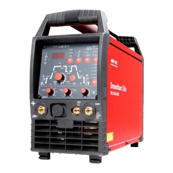
Page 14: Machine Description - Quick Overview
Machine description – quick overview Smootharc TIG 230 AC/DC Machine description – quick overview Smootharc TIG 230 AC/DC 4.1.1 Front view Figure 4-1 Item Symbol Description Machine control See Machine control – operating elements chapter Connection socket, "+" welding current •... -
Page 15: Rear View
Machine description – quick overview Smootharc TIG 230 AC/DC 4.1.2 Rear view Figure 4-2 Item Symbol Description Carrying strap Carrying handle Ignition type changeover switch = HF ignition = Liftarc (contact ignition) 8-pole connection socket Cooling unit control lead Connection socket, 19-pole Remote control connection Main switch, machine on/off 4-pole connection socket... -
Page 16: Machine Control - Operating Elements
Machine description – quick overview Machine control – Operating elements Machine control – Operating elements T 2.30 Puls Automatic VOLT special DC + DC - AMP% AMP% AMP% 4> 4> JOB 0 Figure 4-3 Item Symbol Description Welding process button MMA welding TIG welding Operating mode button... - Page 17 Machine description – quick overview Machine control – Operating elements Item Symbol Description Welding current polarity button Direct current welding with positive polarity on the electrode holder in relation to the workpiece (pole reversal switch, MMA only). DC welding with negative polarity on the torch (or stick electrode holder) in relation to the workpiece.
-
Page 18: Function Sequence
Machine description – quick overview Machine control – Operating elements 4.2.1 Function sequence AMP% AMP% AMP% Figure 4-4 Item Symbol Description Select welding parameters button This button is used to select the welding parameters depending on the welding process and operating mode used. Gas pre-flow time (TIG) Absolute setting range 0.1 s to 5.0 s (0.1 s increments). - Page 19 Machine description – quick overview Machine control – Operating elements Item Symbol Description Tungsten electrode diameter / Ignition optimisation (TIG) Infinitely adjustable from 1 mm to 4 mm or greater (0,1 mm increments) Alternating current balance (TIG AC) Max. setting range: -30 % to +30 % (1% increments). Optimisation of cleaning effect and fusion penetration characteristics.
-
Page 20: Design And Function
Design and function General Design and function General DANGER Risk of injury from electric shock! Contact with live parts, e.g. welding current sockets, is potentially fatal! • Follow safety instructions on the opening pages of the operating instructions. • Commissioning may only be carried out by persons who have the relevant expertise of working with arc welding machines! •... -
Page 21: Installation
Design and function Installation Installation CAUTION Installation site! The machine must not be operated in the open air and must only be set up and operated on a suitable, stable and level base! • The operator must ensure that the ground is non-slip and level, and provide sufficient lighting for the place of work. -
Page 22: Mains Connection
Design and function Mains connection Mains connection DANGER Hazard caused by improper mains connection! An improper mains connection can cause injuries or damage property! • Only use machine with a plug socket that has a correctly fitted protective conductor. • If a mains plug must be fitted, this may only be carried out by an electrician in accordance with the relevant national provisions or regulations (any phase sequence for three-phase machines)! -
Page 23: Tig Welding
Design and function TIG welding TIG welding 5.6.1 Connecting the welding torch and workpiece lead NOTE Prepare welding torch according to the welding task in hand (see operating instructions for the torch). Figure 5-2 Item Symbol Description Connection socket, "-" welding current Welding current lead connection for TIG welding torch G¼"... -
Page 24: Torch Connection Options And Pin Assignments
Design and function TIG welding 5.6.2 Torch connection options and pin assignments Down Uref 10V Uref 10V IH-Down Poti UD/ein Poti UD/ein 5-pole control lead 8-pole control lead 12-pole control lead Figure 5-3 5.6.3 Shielding gas supply (shielding gas cylinder for welding machine) WARNING Incorrect handling of shielding gas cylinders! Incorrect handling of shielding gas cylinders can result in serious and even fatal injury. -
Page 25: Connecting The Shielding Gas Supply
Design and function TIG welding 5.6.3.1 Connecting the shielding gas supply • Place the shielding gas cylinder into the relevant cylinder bracket. • Secure the shielding gas cylinder using a securing chain. Figure 5-4 Item Symbol Description Pressure reducer Shielding gas cylinder Output side of the pressure reducer Cylinder valve •... -
Page 26: Setting The Shielding Gas Quantity
Design and function TIG welding 5.6.3.2 Setting the shielding gas quantity CAUTION Electric shocks! When setting the shielding gas quantity, high voltage ignition pulses or open circuit voltage are applied at the welding torch; these can lead to electric shocks and burning on contact. -
Page 27: Select Welding Task
Design and function Select welding task Select welding task Operating Action Result element Select and display welding process MMA welding TIG welding Select and display welding current polarity Direct current welding with positive polarity at the electrode holder (MMA). DC welding with negative polarity at the torch (or electrode holder) with respect to the workpiece. -
Page 28: Save Welding Tasks (Jobs)
Design and function Select welding task 5.7.1 Save welding tasks (JOBs) All user settings are saved immediately after being modified or changed. No special save command or user input is needed. The last welding parameters that were used are available even after switching off and on again. There are altogether 8 JOBs that can be used to save the respective parameters for different frequently occurring welding tasks. -
Page 29: Welding Data Display
Design and function Select welding task 5.7.2 Welding data display The following welding parameters can be displayed before (nominal values) or during (actual values) welding. Parameter Before welding During welding (nominal values) (actual values) Welding current Welding voltage JOB number Parameter times Frequency, balance Parameter currents... -
Page 30: Tig Welding
Design and function TIG welding TIG welding 5.8.1 Arc ignition 5.8.1.1 HF ignition Figure 5-6 The arc is started without contact from high-voltage ignition pulses. a) Position the welding torch in welding position over the workpiece (distance between the electrode tip and workpiece should be approx. -
Page 31: Optimising The Ignition Characteristics For Pure Tungsten Electrodes
Design and function TIG welding 5.8.2 Optimising the ignition characteristics for pure tungsten electrodes The best ignition and stabilisation of the arc (DC, AC) and optimum spherical cup formation in the tungsten electrode depend on the electrode diameter being used. The set value should correspond to the diameter of the tungsten electrode. -
Page 32: Function Sequences/Operating Modes
Design and function TIG welding 5.8.4 Function sequences/operating modes The parameters for the function sequence are set using the “Select welding parameters” button and the “Welding parameter setting” rotary dial. Pos. Description T 2.30 Puls “Select welding parameters” button Automatic VOLT “Welding parameter setting”... - Page 33 Design and function TIG welding Non-latched mode NOTE When the foot-operated remote control RTF is connected, the machine switches automatically to non-latched operation. The up- and down-slopes are switched off. AMP% start Down Figure 5-9 1st cycle: • Press and hold torch trigger 1. •...
- Page 34 Design and function TIG welding Latched mode NOTE When the foot-operated remote control RTF is connected, the machine switches automatically to non-latched operation. The up- and down-slopes are switched off. AMP% start Down Figure 5-10 Step 1 • Press torch trigger 1, the gas pre-flow time elapses. •...
-
Page 35: Spotarc
Design and function TIG welding 5.8.4.2 SpotArc The TIG SpotArc function is activated with the pulse variant automated frequencies by default, because this combination produces the most effective results. The user can of course combine the function with other pulse variants depending on the selected welding process. NOTE The up-slope and down-slope times should be set to “0 s”... - Page 36 Design and function TIG welding Sequence: • Press and hold torch trigger 1. • The gas pre-flow time elapses. • HF ignition pulses jump from the electrode to the workpiece, the arc ignites. • The welding current flows and immediately assumes the value set for the ignition current I start •...
-
Page 37: Pulses, Function Sequences
Design and function TIG welding 5.8.5 Pulses, function sequences NOTE The function sequences in pulses basically behave in the same way as in standard welding, but during the main current phase there is a continual switching back and forth between the pulse and pause currents at the relevant times. 5.8.5.1 TIG pulses –... -
Page 38: Pulse Variants
Design and function TIG welding 5.8.6 Pulse variants NOTE The machines have an integrated pulse device. With pulses, the machine switches back and forth between the pulse current (main current) and pause current (secondary current). 5.8.6.1 Pulses (thermal pulses) AMP% Figure 5-14 Operating Action... -
Page 39: Automated Pulses
Design and function TIG welding 5.8.6.2 Automated pulses The automated pulses are used with tacking and spot welding of workpieces in particular. An oscillation in the molten pool is produced by the current-dependent pulse frequency and balance, which positively influences the ability to bridge the air gap. The pulse parameters required are automatically specified by the machine control. -
Page 40: Tig Activarc Welding
Design and function TIG welding 5.8.7 TIG activArc welding The EWM activArc process, thanks to the highly dynamic controller system, ensures that the power supplied is kept virtually constant in the event of changes in the distance between the welding torch and the weld pool, e.g. -
Page 41: Welding Torch (Operating Variants)
Design and function TIG welding 5.8.8 Welding torch (operating variants) Different torch versions can be used with this machine. Functions on the operating elements, such as torch triggers (TT), rockers or potentiometers, can be modified individually via torch modes. Explanation of symbols for operating elements: Symbol Description Press torch trigger... -
Page 42: Torch Mode And Up/Down Speed Setting
Design and function TIG welding 5.8.9 Torch mode and up/down speed setting The user has the modes 1 to 4 and modes 11 to 14 available. Modes 11 to 14 include the same function options as 1 to 4, but without tapping function for the secondary current. The function options in the individual modes can be found in the tables for the corresponding torch types. -
Page 43: Standard Tig Torch (5-Pole)
Design and function TIG welding 5.8.9.1 Standard TIG torch (5-pole) Standard torch with one torch trigger: Diagram Operating Explanation of symbols elements BRT1 = Torch trigger 1 (welding current on/off; secondary current via tapping function) Functions mode Operating elements BRT 1 Welding current On/Off (factory-set) BRT 1... - Page 44 Design and function TIG welding Standard torch with one rocker (MG rocker, two torch triggers) Diagram Operating Explanation of symbols elements BRT 1 = torch trigger 1 BRT 2 = torch trigger 2 Functions mode Operating elements BRT 1 Welding current On/Off Secondary current BRT 2 (factory-set)
-
Page 45: Tig Up/Down Torch (8-Pole)
Design and function TIG welding 5.8.9.2 TIG up/down torch (8-pole) Up/down torch with one torch trigger Diagram Operating Explanation of symbols elements TT 1 = torch trigger 1 Functions Mode Operating elements BRT 1 Welding current on/off BRT 1 Secondary current (tapping mode) / (Latched mode) (factory- set) Increase welding current, infinite adjustment (up function) - Page 46 Design and function TIG welding Up/down torch with two torch triggers Diagram Operating Explanation of symbols elements TT 1 = torch trigger 1 (left) TT 2 = torch trigger 2 (right) Functions Mode Operating elements BRT 1 Welding current on/off BRT 2 Secondary current BRT 1...
-
Page 47: Potentiometer Torch (8-Pole)
Design and function TIG welding 5.8.9.3 Potentiometer torch (8-pole) The welding machine needs to be configured for operation with a potentiometer torch (see chap. "Configuring TIG potentiometer torch") Potentiometer torch with one torch trigger: Diagram Operating Explanation of symbols elements BRT 1 = torch trigger 1 Functions Mode... -
Page 48: Retox Tig Torch (12-Pole)
Design and function TIG welding 5.8.9.4 RETOX TIG torch (12-pole) NOTE For operation with this welding torch, the welding machine must be equipped with the retrofit option "ON 12POL RETOX TIG" (12-pole torch connection socket)! Diagram Operating elements Explanation of symbols TT= torch trigger BRT 1 BRT 3... -
Page 49: Mma Welding
Design and function MMA welding MMA welding CAUTION Risk of being crushed or burnt. When replacing spent or new stick electrodes • Switch off machine at the main switch • Wear appropriate safety gloves • Use insulated tongs to remove spent stick electrodes or to move welded workpieces and •... -
Page 50: Select Welding Task
Design and function MMA welding 5.9.2 Select welding task Operating Action Result element Select MMA welding process signal light lights up in green Set welding current 5.9.3 Hotstart The hotstart device improves the ignition of the stick electrodes using an increased ignition current. a) = Hotstart time b) = Hotstart current Welding current... -
Page 51: Remote Control
Design and function Remote control 5.10 Remote control NOTE The remote control is operated on the 19-pole remote control connection socket. • If required, extension cables are available in different lengths (see chapter Accessories). • Plug the remote control unit into the remote control connection socket on the welding machine or wire feed unit and lock it only when the machine is switched off. -
Page 52: Interfaces For Automation
Design and function Interfaces for automation 5.11 Interfaces for automation 5.11.1 Remote control connection socket, 19-pole CAUTION Damage to the machine due to improper connection! Unsuitable control leads or incorrect connection of input and output signals can cause damage to the machine. •... -
Page 53: Advanced Settings
Design and function Advanced settings 5.12 Advanced settings 5.12.1 Testing the machine fan The machine fan can be switched on at the machine controls so that you can check that it is working correctly. VOLT Figure 5-19 Display Setting/selection Lock JOB menu Protect welding parameters from unauthorised access Service menu Service settings... -
Page 54: Limiting The Mains Current (10A)
Design and function Advanced settings 5.12.2 Limiting the mains current (10A) If the plug socket has a 10A mains fuse in order to comply with national regulations, it may be necessary to reduce the mains current of the welding machine to 10A in order to avoid triggering the fuse. This restricts the welding machine's power input. -
Page 55: Protecting Welding Parameters From Unauthorised Access
Design and function Advanced settings 5.12.3 Protecting welding parameters from unauthorised access To protect against unauthorised or unintentional changes to the welding parameters, you can lock the machine controls with a software key (3-digit machine code). If the access lock is active, only the following parameters can be changed: •... -
Page 56: Changing The Three-Digit Machine Code
Design and function Advanced settings 5.12.3.1 Changing the three-digit machine code In this menu you can change the 3-digit machine code. After entering and confirming the old code, you can enter a new code. The correct machine code is necessary for activating and deactivating the access lock! VOLT Figure 5-22 Display... -
Page 57: Setting The Welding Current (Absolute/Percentage)
Design and function Advanced settings 5.12.4 Setting the welding current (absolute/percentage) The welding currents for start current, secondary current, end current and hotstart current can be set as percentages (factory setting) or absolute values. If absolute current display is set, the "AMP" signal light for the main current is lit in addition to the respective "AMP%"... -
Page 58: Selecting The Welding Current Polarity During The Ignition Phase
Design and function Advanced settings 5.12.5 Selecting the welding current polarity during the ignition phase Selection of welding current polarity during ignition phase, until the arc stabilises. It always switches over to DC- polarity after a few milliseconds. VOLT Figure 5-24 Display Setting/selection Lock JOB menu... -
Page 59: Maintenance, Care And Disposal
Maintenance, care and disposal General Maintenance, care and disposal DANGER Risk of injury from electric shock! Cleaning machines that are not disconnected from the mains can lead to serious injuries! • Disconnect the machine completely from the mains. • Remove the mains plug! •... -
Page 60: Repair Work
Maintenance, care and disposal Repair Work Repair Work DANGER Do not carry out any unauthorised repairs or modifications! To avoid injury and equipment damage, the unit must only be repaired or modified by specialist, skilled persons! The warranty becomes null and void in the event of unauthorised interference. •... -
Page 61: Rectifying Faults
Rectifying faults Machine faults (error messages) Rectifying faults All machines are subject to rigorous production checks and final checks. If despite this, anything fails to work at any time, please check the machine using the following chart. If none of the fault rectification procedures described leads to the correct functioning of the machine, please inform your authorised dealer. -
Page 62: Resetting Welding Parameters To The Factory Settings
Rectifying faults Resetting welding parameters to the factory settings Resetting welding parameters to the factory settings NOTE All customised welding parameters that are stored will be replaced by the factory settings. VOLT Figure 7-1 Display Setting/selection Input confirmation User entries are applied, release button(s). 099-000143-BOC01 16.11.2009... -
Page 63: Display Machine Control Software Version
Rectifying faults Resetting welding parameters to the factory settings 7.2.1 Display machine control software version NOTE The query of the software versions only serves to inform the authorised service staff! VOLT Figure 7-2 Display Setting/selection Lock JOB menu Protect welding parameters from unauthorised access Service menu Service settings Exit the menu... -
Page 64: Technical Data
Technical data Smootharc TIG 230 AC/DC Technical data Smootharc TIG 230 AC/DC NOTE Performance specifications and guarantee only in connection with original spare and replacement parts! Setting range Welding current 3 A-230 A 5 A-180 A 5 A-230 A 5 A-180 A Welding voltage 10.1V-19.2V 20.2V-27.2V... -
Page 65: Accessories, Options
Accessories, options TIG welding torch Accessories, options TIG welding torch Type Designation Item no. TIG 200 GD 4M 8P 2T UD TIG welding torch, 4m, gas-cooled, double 094-010981-00200 pressure, U/D TIG 200 GD 4M 12P RETOX TIG welding torch, 4m, gas-cooled, RETOX, flex., 094-011554-00004 leather Electrode holder / workpiece lead...
Need help?
Do you have a question about the Smootharc Elite TIG 230 AC/DC and is the answer not in the manual?
Questions and answers