Table of Contents
Advertisement
Advertisement
Table of Contents

Related Manuals for BOC Smootharc MMA 170


Summary of Contents for BOC Smootharc MMA 170
- Page 1 Smootharc MMA 170 O P E R AT I N G M A N U A L...
-
Page 2: Welcome To A Better Way Of Welding
The document has been prepared in good faith and is professional opinion only. Information in this document has been derived from third parties, and though BOC believes it to be reliable as at the time of printing, BOC makes no representation or warranty as to the accuracy, reliability or completeness of information in this document and does not assume any responsibility for updating any information or correcting any error or omission which may become apparent after the document has been issued. -
Page 3: Table Of Contents
Contents Welcome to a better way of welding 4.0 Machine Specifications and Contents 28 Operating Controls 1.0 Recommended Safety Precautions Health Hazard Information 5.0 Operating Functions Personal Protection Welding selections Electrical Shock Earthing User Responsibility 6.0 Technical Specifications 2.0 Manual Metal Arc Welding Process 7.0 Periodic Maintenance (MMAW) Daily Maintenance... -
Page 4: Recommended Safety Precautions
1.0 Recommended Safety Precautions 1.1 Health Hazard Information • Fumes from the welding of some metals could have an adverse effect on your health. Don’t The actual process of welding is one that breathe them in. If you are welding on material can cause a variety of hazards. - Page 5 • Ensure that no gas is leaking from the cylinder valves. valve connection or the system to which the Don’t repaint or disguise markings and cylinder is connected. DO NOT use ammonia- damage. If damaged, return cylinders to BOC based leak detection fluid as this can damage immediately.
-
Page 6: Electrical Shock
BOC stock a huge range of personal protective If you suspect the valve is damaged, DO equipment. This combined with BOC’s extensive NOT use it. Report the issue to BOC and Gas and Gear network ensures fast, reliable arrange for the cylinder to be returned service throughout the South Pacific. -
Page 7: Manual Metal Arc Welding Process (Mmaw)
The heat of the arc melts the parent metal and the electrode which mix together to form, on BOC supplies a popular range of arc welding cooling, a continuous solid mass. machines. Machines range from small portable welders that operate from standard 240 Volt... -
Page 8: Welding Technique
Volt supply (15 amps Input), has an output of 170 most fabrication using mild steel and for this amps DC @ 50% duty cycle. material has a choice of various standard BOC electrodes, each of which will have qualities Having decided on a welding machine, appropriate suited to particular tasks. - Page 9 BOC Smootharc S 308L E308L Rutile basic coated low carbon electrodes for welding austenitic stainless steel and difficult to weld...
- Page 10 Overhead welding Correct Work Preparation requires a very short arc, so that a minimum of metal will be lost. Certain BOC electrodes have The method of preparation of components to been specially designed for ‘touch’ welding.These...
-
Page 11: Types Of Joints
2.6 Types of Joints Double ‘V’ Butt Weld Used on plate of 12 mm and over Butt Welds in thickness when welding can A butt weld is a weld made between two be applied from both sides. It allows faster welding and greater plates so as to give continuity of section. -
Page 12: Fillet Welds
General notes on Butt Welds LAYERS Electrode Angle for Subsequent Layers The first run in a prepared butt weld should WELD BEADS be deposited with an electrode not larger than 4.0 mm. The angle of the electrode for the WELD METAL various runs in a butt weld is shown. - Page 13 The following terms and definitions are ‘T’ Joints important in specifying and describing A fillet weld may be placed either fillet welds. on one or both sides, depending on the requirements of the work. Leg Length The weld metal should fuse into or penetrate the corner formed A fusion face of a fillet weld, as shown below.
- Page 14 Fillet Weld Data Concave Fillet Weld A fillet in which the contour of the weld is Nominal Minimum Plate Electrode below a straight line joining the toes of the Fillet Size Throat Thickness Size (mm) weld. It should be noted that a concave fillet (mm) Thickness (mm)
-
Page 15: Typical Defects Due To Faulty Technique
Shielded metal arc welding, like other welding penetration is poor, each run is small, concave processes, has welding procedure problems and smooth (only BOC Smootharc 13 is that may develop which can cause defects suitable for this position). in the weld. Some defects are caused by The downwards method should be used for problems with the materials. - Page 16 Slag inclusions occur when slag particles are type and size of electrode and the welding trapped inside the weld metal which produces a position weaker weld. These can be caused by: • holding the arc as short as possible • erratic travel speed •...
-
Page 17: Gas Tungsten Arc Welding (Gtaw/Tig)
3.0 Gas Tungsten Arc Welding (GTAW/TIG) 3.1 Introduction Direct or alternating current power sources with constant current output characteristics The Tungsten Inert Gas, or TIG process, uses are normally employed to supply the welding the heat generated by an electric arc struck current. -
Page 18: Process Variables
Lift Arc™ DCEN - Narrow bead - Deep penetration During this method of arc initiation, the tungsten is actually touching the workpiece. Nozzle This occurs at very low amperage that is only sufficient to pre-heat, not melt the tungsten. As the tungsten is moved off the plate, the arc Ions Electrons is established. -
Page 19: Welding Techniques
3.4 Welding Techniques Welding techniques The suggested electrode and welding rod angles for welding Vertical a bead on plate. The same angles are used when making Welding Rod a butt weld. The torch is held 60–75° 60–75° from the metal surface. Shield gas Nozzle This is the same as holding the... -
Page 20: Shielding Gas Selection
3.5 Shielding Gas Selection Brass With argon, the arc is stable and there is little smoke. Cobalt-based alloys Argon provides a stable, easy-to-control arc. Copper nickel (Monel) Argon gives a stable, easy-to-control arc. Also used for welding copper nickel to steel. Deoxidised copper Helium is preferred as it helps greatly in counteracting thermal conductivity of copper. -
Page 21: Consumable Selection
Welding wire The following table includes the recommended welding consumable for the most commonly welded materials. Base Material BOC Consumable C-Mn and low Carbon steels BOC Mild steel TIG wire Low Alloy steels 1.25Cr/0.5Mo Comweld CrMo1 2.5Cr/1Mo Comweld CrMo2... - Page 22 b) Non consumable Tungstens Tungsten Electrode Selector Chart Base metal type Thickness range Desired results Welding Electrode type current Copper alloys, General purpose DCSP 2% Thoriated (EW-Th2) Cu-NI alloys and Nickel alloys 2% Ceriated (EW-Ce2) Only thin sections Control penetration ACHF Zirconiated (EW-Zr) Only thick sections...
- Page 23 Shielding Tungsten performance characteristics 75% Argon/ Best stability at medium currents. Good arc starts. Medium tendency to spit. 25% Helium Medium erosion rate. 75% Argon/ Low erosion rate. Wide current range. AC or DC. No spitting. Consistent arc starts. 25% Helium Good stability.
- Page 24 Tungsten tip preparation Tungsten Grinding Shape by grinding longitudinally DCSP (EN) or DCRP (EP) (never radially). Remove the sharp point to leave a = Diameter Flat truncated point with a flat 1/4–1/2x Dia spot. Diameter of flat spot determines amperage capacity. (See below) Taper length 2–3x Dia...
-
Page 25: Typical Welding Joints For Gas Tungsten Arc Welding
3.7 Typical Welding Joints for Gas T -joint Tungsten Arc Welding When welding a T-joint, the edge and the flat surface are to be joined together, and the Butt welds edge will melt faster. Angle the torch to direct TIG welding is commonly combined with other more heat to the flat surface and extend the faster filling processes such as MMA or MIG electrode beyond the cup to hold a shorter arc. - Page 26 Troubleshooting guide Problem Cause Solution Excessive 1. Inadequate gas flow 1. Increase gas flow electrode 2. Improper size electrode for 2. Use larger electrode consumption current required 3. Operating of reverse polarity 3. User larger electrode or change polarity 4. Electrode contamination 4.
- Page 27 Troubleshooting guide Problem Cause Solution Porosity 5. Alloy impurities in the base metal 5. Change to a different alloy composition which is in Weld such as sulphur, phosphorous, lead weldable. These impurities can cause a tendency to Deposit and zinc crack when hot.
-
Page 28: Machine Specifications And Contents
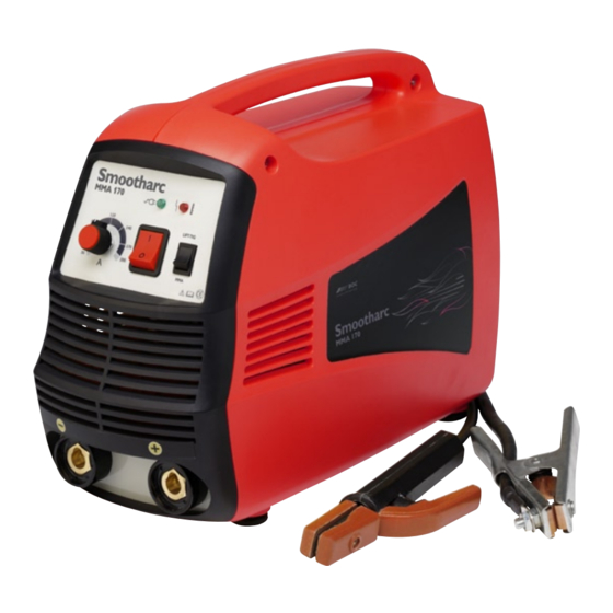
4.0 Machine Specifications and Contents 4.1 Operating Controls Power indicator light Overtemperature control indicator Welding current regulator On/Off switch Process selector switch MMA/Lift TIG Heavy duty 15A input plug Negative '35' dinse connector Positive '35' dinse connector... -
Page 29: Operating Functions
5.0 Operating Functions 5.1 Welding selections Manual Metal Arc welding (MMA) Select the current as per the ■ recommendations of the consumable manufacturer. Select the polarity of the electrode cable as ■ per the recommendations (+/-) Select the process selector switch to MMA ■... -
Page 30: Technical Specifications
6.0 Technical Specifications MMA170 Part No. MMA170P Input Voltage (V) 1PH AC240V±15% Frequency (Hz) 50/60 Input Plug Requirement Industrial Heavy duty 15A Rated Current 27.5 20.3 No-load Voltage (V) Output Current Range (A) 20-170 Rated Output Voltage (V) 26.8 16.8 Duty Cycle (%) 100% 170A... -
Page 31: Periodic Maintenance
If problems in use are not solved with above mentioned measures, please contact your local 7.1 Daily Maintenance BOC representative. Perform the following maintenance daily: • Clean electrode holder and TIG torch's gas nozzle. Replace damaged or worn parts. -
Page 32: Terms Of Warranty
• Valid for 18 months from date of purchase. serial number of the equipment in order to • An authorised BOC Service Agent must carry validate the warranty. out warranty repairs. • The parts replaced under the terms of the •... -
Page 33: Recommended Safety Guidelines
9.0 Recommended Safety Guidelines Some safety precautions BOC recommends are as follows: • Repair or replace defective cables immediately. • Keep fire extinguishing equipment at a handy location in the shop. • Never watch the arc except through lenses of the correct shade. - Page 36 AUSTRALIA BOC is a trading name of BOC Limited, a member of The Linde Group, © BOC Limited 2009. Reproduction without permission is strictly prohibited. Details given in this document are believed to be correct at the time of printing. Whilst proper care has been taken in the preparation, no liability for injury or damage resulting from its improper use can be accepted.
Need help?
Do you have a question about the Smootharc MMA 170 and is the answer not in the manual?
Questions and answers