Table of Contents
Advertisement
Quick Links
µEZ GUI Start Here Guide
Introduction
At Future Designs, our goal is to make it easy for our customers to get their projects up and running as
quickly as possible. In this guide, you will develop a simple graphical user interface (GUI) on the µEZ
platform to demonstrate how to use some of the core features of emWin and µEZ. Using this "Hello
World" type of walkthrough as a starting point, we hope to shorten the learning curve for GUI
development. Aside from this document, there are many additional resources available at
www.TeamFDI.com. If you ever need more help, contact us and we will be happy to assist you.
Hardware Used in This Guide: (Included in Kit)
UEZGUI-1788-43WQR-BA
SEGGER J-Link Lite Probe
FDI J-Link 20-pin to mini-10 pin adapter model JLINK-ARM-AD
USB Type A to USB Type Mini B Cable (2x)
Universal AC to 5V USB plug Power Supply Unit
Software Used in This Guide:
(Installation and usage instructions are provided within the guide)
SEGGER J-Link Software
µEZ Source w/ Project Maker (v2.08 or later)
One of the following IDEs:
o Rowley CrossWorks v3.6.5
o IAR Embedded Workbench v7.60
Files Used in This Guide:
(Installation and usage instructions are provided within the guide)
Start Here Project Files (located in the µEZ source download)
Rev. 1.11 Aug 31, 2016
www.TeamFDI.com
UEZGUI-1788-43WQR
FDI_AN_µEZ_009
Page 1
Advertisement
Table of Contents

Related Manuals for FDI uEZ GUI


Summary of Contents for FDI uEZ GUI
- Page 1 UEZGUI-1788-43WQR-BA SEGGER J-Link Lite Probe FDI J-Link 20-pin to mini-10 pin adapter model JLINK-ARM-AD USB Type A to USB Type Mini B Cable (2x) Universal AC to 5V USB plug Power Supply Unit Software Used in This Guide: (Installation and usage instructions are provided within the guide) ...
-
Page 2: Table Of Contents
Website and Support ................28 Important Legal Information Information in this document is provided solely to enable the use of Future Designs products. FDI assumes no liability whatsoever, including infringement of any patent or copyright. FDI reserves the right to make changes to these specifications at any time, without notice. -
Page 3: Hardware Verification
It also contains user manuals, schematics, and documentation for the product including this guide. FDI recommends that you visit the documentation tab of the product page of your µEZ GUI to get the latest documentation. -
Page 4: J-Link Installation
Linux ARMV7: http://tinyurl.com/zat25fs C. µEZ Installation µEZ is a middleware API library built on FreeRTOS and emWin. It is created, managed and regularly updated by FDI. Download the latest µEZ release at the link provided below: EZ (v2.08): https://sourceforge.net/projects/uez/ Extract the µEZ 7z, or zip file, to the desired location. -
Page 5: Connecting The J-Link Debugger To The Μez Gui For Programming
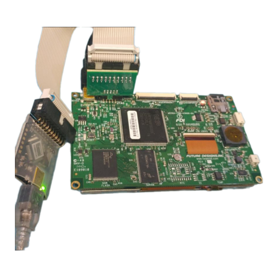
2. Connect the J-Link probe to the FDI mini-10 pin JTAG connector (J5) on the bottom side of the µEZ GUI. The J-Link ribbon cable and FDI adapter for the µEZ GUI are supplied in the kit. The 10-pin connector can only be connected one way. -
Page 6: Building And Running The Initial Project
GUI Start Here Guide UEZGUI-1788-43WQR More complex functions such as managing windows, button widgets, list-view widgets, edit widgets, etc. Displaying images. Support for multiple displays. Support for multiple layers and transparency settings. Control of GUI by mouse and touch screen. - Page 7 GUI Start Here Guide UEZGUI-1788-43WQR 3. Navigate through the uEZ folder to uEZ_v2.XX_SourceForge/uEZ/Build/Generic/NXP. Then, locate the folder corresponding to the microcontroller used in the EZ GUI. NOTE: The processor number is the first set of numbers in the model number of the µEZ GUI.
- Page 8 GUI Start Here Guide UEZGUI-1788-43WQR 5. After the project opens: For IAR: Select the “Debug” Build from the workspace menu if not already selected. For Crossworks: Select the “Project Explorer” sub-window if not already selected. 6. Next building the project: For IAR: Select “Project >...
- Page 9 GUI Start Here Guide UEZGUI-1788-43WQR 9. Next open up the actual start here project by navigating to the appropriate location: For IAR the workspace file is at StartHere\Build\uEZGUI_1788_43WQR\IAR\uEZGUI_StartHere.eww. For Crossworks the project file is at StartHere\Build\uEZGUI_1788_43WQR\Crossworks\uEZGUI_StartHere.hzp. Figure 10: Start Here...
- Page 10 GUI Start Here Guide UEZGUI-1788-43WQR Figure 12: Debug Settings 14. Click the [OK] button to exit the dialog. Proceed to step 17 15. If using Crossworks, proceed to step 16, otherwise proceed to step 17. 16. Click “Target > Connect > SEGGER J-Link” from the drop down menu. This activates the J-Link probe.
-
Page 11: Adding A Button To The Home Screen
GUI Start Here Guide UEZGUI-1788-43WQR To see where the window is developed, examine the folder structure of the initial project. Figure 15: File Hierarchy All of the source code used to provide functionality to the project is within the “Source\App”... - Page 12 GUI Start Here Guide UEZGUI-1788-43WQR The remainder of the file contains the emWin event handler function and a window setup function. Any callback function that is used for widgets will also be placed in this section. NOTE: Most of the code segments in this guide are formatted to be copied and pasted to assist you in easily applying the code to your project.
- Page 13 GUI Start Here Guide UEZGUI-1788-43WQR 2. Replace the definitions with the names and values associated with the new button being created: /*---------------------------------------------------------------------------* * Constants: *--------------------------------------------------------------------------*/ #define ID_WINDOW (GUI_ID_USER + 0x00) #define ID_TITLE_TEXT (GUI_ID_USER + 0x01) #define ID_MYBUTTON_BUTTON (GUI_ID_USER + 0x02)
- Page 14 GUI Start Here Guide UEZGUI-1788-43WQR 3. The two arrays under the section header “Local Data” still contain the information from the “Start Here” text. Each widget is represented in one of the sections within each array. Identify where the “Start Here” text is.
-
Page 15: Creating A New Window
GUI Start Here Guide UEZGUI-1788-43WQR /** Generic Mapping of Screen Layout*/ static T_LAFMapping HomeScreenMapping[] = { { ID_WINDOW, "", GUI_BLACK, GUI_WHITE, &FONT_SMALL, LAFSetupWindow, 0}, { ID_TITLE_TEXT, "My Main Screen", GUI_BLACK, GUI_WHITE, &FONT_LARGE, LAFSetupText, 0}, { ID_MYBUTTON_BUTTON, "Temperature", GUI_GRAY, GUI_BLACK, &FONT_LARGE,... - Page 16 GUI Start Here Guide UEZGUI-1788-43WQR NOTE: To simplify this process, just press Ctrl+H to open the Find and Replace dialog. Insert “HomeScreen” in the Find what field and “SecondScreen” in the Replace with field. Select Match case and make sure Match whole word is unselected. Click Replace All and the entire document will be updated.
- Page 17 GUI Start Here Guide UEZGUI-1788-43WQR 8. The two arrays that hold the information for the various widgets on a window are shown below. Delete the lines highlighted in red that are specific to the first window. The only remaining values within each of these array variables define the window’s properties and title text that will be used by emWin to setup the window.
- Page 18 GUI Start Here Guide UEZGUI-1788-43WQR 9. This file now contains the minimum required information to setup a blank window. The final step to creating the window is to update the WindowManager.c file. Open the file and update the WindowManager_Create_All_Active _Windows function as...
-
Page 19: Adding Callback Functionality
GUI Start Here Guide UEZGUI-1788-43WQR E. Adding Callback Functionality Now that the second screen has been created, return to HomeScreen.c and add a callback function to the previously created button. Once this callback function is created, the button will switch to the newly created second window when it is pressed. -
Page 20: Interfacing With The Onboard Temperature Sensor
GUI Start Here Guide UEZGUI-1788-43WQR /*-------------------------------------------------------------------------* * Routine: IHandleSecondScreen *-------------------------------------------------------------------------* * Description: Change to the second screen when the temperature button is pressed. *-------------------------------------------------------------------------*/ static TBool IHandleSecondScreen(WM_MESSAGE * pMsg, aNCode, aID) (aNCode == WM_NOTIFICATION_RELEASED) { WindowManager_Show_Window(SECOND_SCREEN); return EFalse; 4. Use the appropriate steps to Build, download, debug, and run the updated project to test the functionality. - Page 21 GUI Start Here Guide UEZGUI-1788-43WQR NOTE: The µEZ GUI screen coordinates are defined such that the coordinates (0,0) are located at the upper left corner of the screen. 4. Add the temperature widget to each of the “Local Data” arrays. This text field will not need a callback function.
-
Page 22: Creating A Task
GUI Start Here Guide UEZGUI-1788-43WQR G. Creating a Task The next set of steps will describe the process for setting up a new task to monitor the data provided by the onboard I C digital temperature sensor. Creating new tasks allows multiple continuous processes to operate “simultaneously”... - Page 23 GUI Start Here Guide UEZGUI-1788-43WQR #include <uEZ.h> #include <uEZTemperature.h> #include <uEZGPIO.h> #include <uEZProcessor.h> #include "MyTask.h" #include <stdio.h> extern void UpdateTemp(char *myString); // Access to function in SecondScreen.c TUInt32 TemperatureLoopTask(T_uezTask aMyTask, void *aParams) { char myString[10] = ""; // String to hold temperature TInt32 i, f;...
-
Page 24: Adding A Back Button
GUI Start Here Guide UEZGUI-1788-43WQR 5. Use the appropriate steps to Build, download, debug, and run the updated project to verify that there are no errors. The temperature on the second screen should display an accurate reading. Figure 18:... - Page 25 GUI Start Here Guide UEZGUI-1788-43WQR #define ID_WINDOW (GUI_ID_USER + 0x00) #define ID_TITLE_TEXT (GUI_ID_USER + 0x01) #define ID_TEMP_TEXT (GUI_ID_USER + 0x02) #define ID_BACK_BUTTON (GUI_ID_USER + 0x03) // ID #define WINDOW_XSIZE (UEZ_LCD_DISPLAY_WIDTH) #define WINDOW_YSIZE (UEZ_LCD_DISPLAY_HEIGHT) #define WINDOW_XPOS #define WINDOW_YPOS #define TITLE_TEXT_XSIZE...
- Page 26 GUI Start Here Guide UEZGUI-1788-43WQR 3. Add a line in both of the local data arrays for the new back button. /*---------------------------------------------------------------------------* * Local Data: *---------------------------------------------------------------------------*/ /** Structure to hold all of the widgets used in this dialog*/ static const...
-
Page 27: Restoring The Out-Of-Box (Oob) Demo (Optional)
GUI Start Here Guide UEZGUI-1788-43WQR Figure 19: Final Screen Congratulations! This concludes the walkthrough for building a simple GUI! Professional looking designs with complex functionality can be designed using advanced features provided in the emWin and µEZ libraries. Documentation and support for learning these features is available through Future Designs, Inc. -
Page 28: Next Steps
TTL UART Serial Communications: ..................http://tinyurl.com/zrc7gp2 Video Conversion Guide: ....................http://tinyurl.com/jxthcvv FDI also provides documentation for using the demo bootloader for playing videos and slideshows as well as running other applications from the menu. Slideshow Creation Guide: ....................http://tinyurl.com/zlu9ood ...
Need help?
Do you have a question about the uEZ GUI and is the answer not in the manual?
Questions and answers