
Related Manuals for flamco Logotherm LogoThermic G2


Summary of Contents for flamco Logotherm LogoThermic G2
- Page 1 Logotherm LogoThermic G2 Thermostatically controlled heat interface units S-Line, 35 kW (UC/MC) M-Line, 46 kW (UC/MC) Installation and servicing instructions www.flamcogroup.com/manuals...
- Page 2 Acronyms Domestic water, cold Domestic hot water Domestic water circulation Domestic water heating Heating flow line Heating return line Unmixed heating circuit Mixed heating circuit Plate heat exchanger Male thread Female thread prim. Primary heating circuit (heat supply) sec. Secondary heating circuit (heat consumer) Heat flow meter SM/FM Surface-mounted / flush-mounted...
-
Page 3: Table Of Contents
Table of contents Acronyms .......................... 2 Safety instructions ....................5 Intended use ........................6 1.1.1 Use for intended purpose ........................ 6 1.1.2 Improper use ............................ 7 Device designation .......................7 Hazard notes ........................7 What to do in the event of breakdown or leaks ..............8 Spare and wear parts ......................8 Requirements on trained engineers ..................8 Liability and copyrights ......................9... - Page 4 Optional accessories ....................27 Additional static heating circuit (only for MC variants) ............28 6.1.1 Additional static heating circuit (for MC) and simultaneous heating circuit distribution... 28 Heating circuit manifold for surface-mounted / flush-mounted variants ......30 6.2.1 Standard manifold with 3 to 8 heating circuits for MC variants ........... 30 6.2.2 Underfloor manifold with 3 to 12 heating circuits (wide version) ..........
-
Page 5: Safety Instructions
1. Safety instructions Please follow these safety instructions carefully to prevent hazards and injury to persons and property. These operating instructions are primarily designed for the safe use and installation of the device and make no claims to completeness. These operating instructions describe the functionality of the device and are intended to provide information about the required safety instructions and to draw attention to possible hazards. -
Page 6: Intended Use
Permissible mains supply and operating parameters - Heating side/primary side: Permissible pressure rating: PN10 Max. permissible operating temperature: 90°C Max. permissible differential pressure: 2.0 bar - With actuator for zone valve: 1.0 bar - Sanitation side: Permissible pressure rating: PN10 Max. -
Page 7: Improper Use
In particular, please check the permissible limit values, e.g. electrical conductivity, the pH value, the water hardness level and the ammonium concentration. Furthermore, in Germany all applicable norms, regulations and guidelines specific to the federal states must be taken into consideration, alongside the instructions in the applicable installation and operating manuals. -
Page 8: What To Do In The Event Of Breakdown Or Leaks
Life-threatening electric shocks can be caused by spraying or splashing water. Escaping water may also disable the safety devices. Any changes made to the unit that have not been authorised by the manufacturer will invalidate any warranty claims. Residual hazards: The product has been built in accordance with the most relevant and recognised safety regulations. -
Page 9: Liability And Copyrights
1.7 Liability and copyrights We reserve all copyrights to this document. Any misuse, in particular reproduction or disclosure to third parties, is prohibited. This original operating manual may not be reproduced or distributed, either in part or in its entirety, without the express permission of the manufacturer. -
Page 10: Logothermic Units
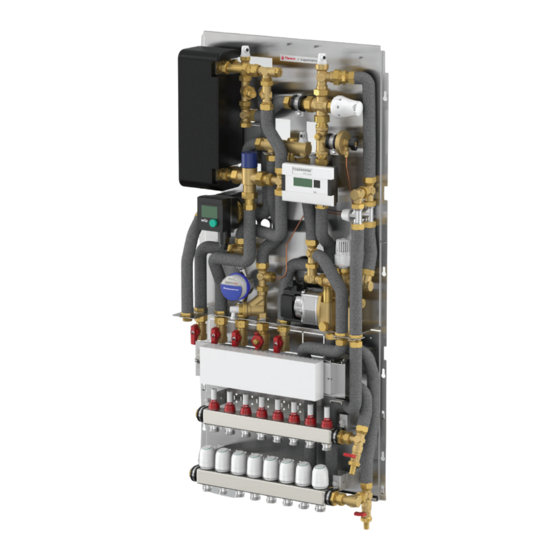
Further features Adaptors for a heat and cold water meter are included in the scope of supply with every station. - Other accessories according to current price list Fig. application example LogoThermic units 3.1 Technical data 3.1.1 HIU characteristics and performance parameters •... - Page 11 Performance parameters: Draw-off capacity S-Line 12 l/min (35 kW); M-Line 17 l/min (46 kW) at approx. 1 bar pressure loss, at max. 40 K heating and 65°C FL temperature Heating capacity - residential unit up to 10 kW (20 K) Max.
-
Page 12: Components And Hydraulic Diagram
3.1.2 Components and hydraulic diagram Models: LogoThermic G2, UC LogoThermic G2, MC Hydraulic function diagram: LogoThermic G2, UC LogoThermic G2, MC (with optional UC) * Example figure LogoThermic G2 Manual... - Page 13 Legend: Description of components Stainless steel plate heat exchanger (copper or stainless steel brazed; or copper brazed with sealing) Circulation bridge (35 to 65°C) with forced leakage (for RL temperature limitation), Factory setting: 1.5 rotations up Thermostatic three-way valve DN 20, Kvs=3.5 in RL and startec 4-M30x1.5 thermostatic head for setting the priority switching (20 to 50°C) 0.17 mm/K with 2 m remote sensor, factory setting: Mark number 30, or 45 for DWC variants Flamcomix 1"...
-
Page 14: Dimensions
3.1.3 Dimensions Dimensions of the unit with base plate and connection holes (in mm): LogoThermic G2, UC LogoThermic G2, MC 3.2 Variants 3.2.1 LogoThermic G2 with domestic hot water circulation (DWC) The domestic water circulation system is (DWC) used to provide a constant supply of domestic hot water (DHW) to the taps. - Page 15 Notes: The water content of the longest DHW line (without taking DWC into account) should not begreater than 3 litres. Any possible health risk (e.g. Legionella growth) versus possible energy savings must be borne in mind when setting up and operating the DWC system. The relevant applicable technical rules and valid standards must be observed and complied with.
-
Page 16: Special Variants
Dimensions: LogoThermic G2, UC with DWC LogoThermic G2, MC with DWC Example representation Pump characteristic curve: Areas of use of the DWC pump: Media temperature = 2 to 95°C, ambient temperature = 2 to 40°C, max. 10 bar, pump protection code: IP42 The domestic water circulation pump is suitable for use in hard water up to 20°dH. -
Page 17: Installation
4. Installation Please follow the safety instructions contained in this document and any additional assembly instructions during installation! Installing and operating the stations incorrectly will invalidate any warranty claims. The LogoThermic heat interface station can be installed as follows: A) Wall-mounted with surface-mounted cover B) Flush or shaft-mounted (set into wall) with flush-mounted cover or corresponding installation frame Corresponding surface-mounted and flush-mounted covers are available as accessories 4.1 SM/FM mounting rail with 7 ball valves (for MC/UC) -
Page 18: Dn20 Ball Valves, Straight
4.2 DN20 ball valves, straight Legend, see Section 3.1.2 Ball valves with ¾" FT x ¾" FT union nut, with 1 ball valve with sensor Art. No. mount for HFM and domestic water ball valves, DVGW-tested Version with 7 ball valves (as shown above) M10252.32 Version with 8 ball valves, for e.g. -
Page 19: Optional Water Meter Installation
4.3.2 Optional water meter installation LogoThermic G2 HIUs are fitted with an adaptor (with L = 110 mm, 2x ¾" MT) for a cold water meter (B1) that must be removed before the water meter is installed. Procedure: All shut-off valves "A" (if present) on the unit must be closed. -
Page 20: Dirt Traps
5.2 Dirt traps Dirt traps in the units’ SL connection (and the domestic RL for UC versions) protects the system against sludge and impurities. Detailed structure of a dirt trap (example illustrations): The dirt traps can be cleaned by flushing through the drainage device (4) or by removing the locking screw (3) and removing the sieve insert. -
Page 21: Zone Valve For Heating Circuit
5.3 Zone valve for heating circuit The pre-adjustable zone valve in the heat interface unit limits the hot water flow rate to the heating circuit to compensate for the higher pressure losses during the heating of the hot water. To avoid flow noise in the apartment, it is advisable to adjust the zone valve in accordance with the design documents. -
Page 22: Differential Pressure Regulator
Setting curves for the zone valve: Note: In the case of an existing heat meter, the volume flow can also be set with the aid of the heat meter. 5.4 Differential pressure regulator For the specifications for setting the differential pressure regulator, please refer to the design documents. -
Page 23: Thermostatic Circulation Bridge
Valve settings for desired differential pressure 20-40 kPa Rotations Dp [kPa] Setting with 4-mm hexagon socket wrench. Note: a change in the differential pressure regulator leads to a change in the control behaviour. 5.5 Thermostatic circulation bridge The thermostatic circulation bridge guaran- tees uninterrupted provision of the heating medium for water heating. -
Page 24: Thermostatic Control Valves
5.6 Thermostatic control valves Item Description The 3-way valve is for switching between heating and the DHW supply (priority switching) Switching occurs when cold domestic water flows into the heat exchanger. Setting recommendation for the thermostatic head: Mark numbers: 30 (without sanitary circulation) | 45 (with sanitary circulation) The 3-way valve consists of: -startec 4 (M30x1.5) thermostatic head with setting range 20 to 50 (incl. -
Page 25: Thermostatic Domestic Water Mixing Valve, Flamcomix
5.6.1 Thermostatic domestic water mixing valve, Flamcomix Factory setting: 3 turns from closed Functionality based on a sectional view: Setting options Service and maintenance Unisilkon L250L We reserve the right to change the designs and technical specifications of our products. -
Page 26: Thermostatic Head, Type Rotherm Ii (Only For Stations With Mixed Heating Circuit)
5.6.2 Thermostatic head, type Rotherm II (only for stations with mixed heating circuit) The following fixing option is available for the Example: Locking the thermostatic head at 40: thermostatic head, type Rotherm II (item C) Remove the Remove the two thermostatic head metal pins with from the valve... -
Page 27: Heating Circuit Pump
5.7.2 Heating circuit pump Electrical data: 230 V, 50 Hz Number of P1 (W) I1/1 [A] Revolutions MIN. 0.07 MAX. 0.52 Performance characteristic: Technical data: Operating pressure: max. 1.0 MPa Minimum supply pressure: 0.05 MPa Media temperature: +2 to +110°C The pump is equipped with an operating key. -
Page 28: Optional Accessories
6. Optional accessories Note: Some examples are described in the following sections. The illustrations are examples. For other products, such as terminal strips for underfloor manifolds, room temperature controllers, see the corresponding price list or planning document. 6.1 Additional static heating circuit (only for MC variants) After removing the relevant ¾"... -
Page 29: Additional Static Heating Circuit (For Mc) And Simultaneous Heating Circuit Distribution
6.1.1 Additional static heating circuit (for MC) and simultaneous heating circuit distribution LogoThermic G2, MC with 3-8 HC LogoThermic G2, MC with 3-12 HC Example representation with optional DWC, CH, Example representation with optional DWC, CH, water/heat meter, STM and terminal strip water/heat meter, STM and terminal strip Item Designation... -
Page 30: Heating Circuit Manifold For Surface-Mounted / Flush-Mounted Variants
Dimensions and connections LogoThermic G2, MC with 3 - 8 HC LogoThermic G2, MC with 3 - 12 HC Example representations 6.2 Heating circuit manifold for surface-mounted / flush-mounted variants Manifold variants: Standard: 3 to 8 heating circuits Wide version: 3 to 12 heating circuits Features: - Emptying, bleed valve in the flow and return line, max. -
Page 31: Standard Manifold With 3 To 8 Heating Circuits For Mc Variants
6.2.1 Standard manifold with 3 to 8 heating circuits for MC variants Heating circuit manifold (connected to compact mixing circuit) for LogoThermic G2, MC variants 8x UFH manifold (example representation): Note: Up to 8 heating circuit outlets are supplied at 100% per outlet piece. After that, the output is divided among all the other heating circuits. -
Page 32: For Mc Variants
6.2.2.1 For MC variants Heating circuit manifold (connected to compact mixing circuit) for LogoThermic G2 MC variants Legend: LogoThermic G2 MC unit Lateral piping (Art. No.: M10253.15) as optional connection set for MC UFH manifold, 3-12 HC, wide version 6.2.2.2 For UC variants Heating circuit manifold (connected via lateral mixer group) for LogoThermic G2 UC variants Hydraulic diagram To the side mixer group:... - Page 33 Legend: LogoThermic G2, UC station Side connection set with HE pump, as thermostatic M10512.26 mixing circuit Underfloor heating circuit manifold 3-12 HC See Section 6.2.2 Item Components where belonging to (B) Comment Vent stoppers ½" Zone valve ¾" Thermostatic head M30x1.5 lockable, please observe Adjustment range: 20…70°C the following setting values accordingly FL connection option UC...
-
Page 34: Terminal Strip For Underfloor Heating Circuit Manifolds
6.2.3 Terminal strip for underfloor heating circuit manifolds See Section 6.2.2.2 for item 10 Notes: on UFH terminal strip (IP44, supply voltage of actuator 230 V): - up to 8/12 zones (up to 18 actuators can be connected in total) - with pump logic module - incl. - Page 35 Wiring plan for controlling actuators in HC manifolds Electrical connection and wiring plan for controlling LogoThermic G2 stations with optional components (such as room thermostats): Attention: Electrical connection work may only be carried out by authorised electricians! Note the safety instructions (see Section 1) We reserve the right to change the designs and technical specifications of our products.
-
Page 36: Covers And Installation Examples
6.3 Covers and installation examples Depth specifications of LogoThermic G2 UC/MC stations depending on equipment: with heating with pre-wiring With DWC FM [mm] SM [mm] circuit manifold concept ✓ ✓ ✓ ✓ ✓ ✓ ✓ ✓ ✓ ✓ ✓ ✓ ✓... -
Page 37: Overview Of Flush-Mounted Covers (Fm)
6.3.2 Overview of flush-mounted covers (FM) Fig. FM, dimensions in [mm] Installation dimensions External dimensions Flush-mounted cover, completely sealed, Height A1 Width A2 Depth A3 Cover trim Cover trim coated steel, white (RAL 9016) (from-to) height B1 width B2 110-160 Art. -
Page 38: Fm Installation Examples
6.3.3 FM installation examples 6.3.3.1 Long version Flush-mounted cover: open at bottom, wall-hanging (white, RAL 9016) Structure and dimensions: Warning! Observe minimum installation depths. With UFH manifold: 160 mm (without terminal strip 140 mm) With circulation: 160 mm Note the installation depth for on-site HFM! Art. -
Page 39: Standard Version
6.3.3.2 Standard version Flush-mounted cover: completely sealed, wall-hanging, incl. drip tray (white, RAL 9016) Structure and dimensions: Warning! Observe minimum installation depths of 110 mm. With stat. HC: 140 mm With circulation: 160 mm Note the installation depth for on-site HFM! Art. -
Page 40: Wide Version
6.3.3.3 Wide version Flush-mounted cover: open at bottom, wall-hanging (white, RAL 9016) Structure and dimensions: Warning! Observe minimum installation depths of 165 mm. Note the installation depth for on-site HFM! Art. No.: M11100.42 M10203.181 M11100.71 Legend: Mounting frame with drip tray Revision frame (depth adjustable) Door with locks Optional mounting rail (further details: see seperate instructions) -
Page 41: Configuration Examples
6.4 Configuration examples 6.4.1 Example I - LT M-Line with 12x UFH manifold via side mixer group Component list (I) Item Designation Art. No. (example) LogoThermic G2, UC, M-Line 17 L station M11124.81 Lateral mixer group with zone valve and HE pump M10512.26 12x UFH manifold M10512.42... -
Page 42: Example Ii - Lt + M-Line With Dwc, Stat. Hc And 12X Ufh Manifold Via Connection Set
6.4.2 Example II - LT + M-Line with DWC, stat. HC and 12x UFH manifold via connection set Component list (II) Item Designation Art. No. (example) LogoThermic G2, MC, DHW-C, M-Line 17 L unit M11124.911 with DWC connection and Z-pump For item A incl. -
Page 43: Example Iii - Lt+, M-Line With Dwc, Stat. Hc And 8X Ufh Manifold
6.4.3 Example III - LT+, M-Line with DWC, stat. HC and 8x UFH manifold Component list (III) Item Designation Art. No. (example) LogoThermic G2, MC, DHW-C, M-Line 17 L unit M11124.911 with DWC connection and Z-pump For item A incl. with thermostat. -
Page 44: Commissioning
7. Commissioning Before using our products, they must be checked for suitability for the respective planned application. Please bear in mind the water quality at the installation location, particularly for domestic water applications. In the case of critical domestic water qualities, please take suitable measures where necessary (e.g. water treatment) in order to prevent functional impairment and/or damage, e.g. -
Page 45: Notes On Thermostatically Controlled Interface Stations
If you have any questions, please contact your installation company or Flamco customer service. We reserve the right to change the designs and technical specifications of our products. -
Page 46: Information Regarding Domestic Water Hardness
8.1 Information regarding domestic water hardness The propensity for natural water to form limescale deposits depends, among other things, on various factors such as the concentration of calcium and magnesium salts, the pH value and the temperature. If what is known as the lime-carbonic acid balance has been disturbed by an increase in the pH value and/or the temperature, the calcium carbonate precipitates in the form of calcite crystals. -
Page 47: Maintenance Checklist
8.2 Maintenance checklist Work to be carried out during annual maintenance (by the specialist installer or factory customer service) Visual inspection * Completed and OK? Screw connections and - Leak-tightness check fittings Heat exchanger - Leak-tightness check Electrical wiring - Check the electrical wiring for abnormalities (e.g. -
Page 48: Pressure Loss Diagram
9. Pressure loss diagram Diagramm, Primär* Volumetric flow – Pressure loss – Diagram, primary* LogoThermic G2 S-Line 1000 *3 - W - switching valve fully open Flow rate (l/h) Adaptor DP - controller, HFM Volumetric flow – Pressure loss – Diagram, primary* LogoThermic G2 M-Line 1000 *3 - W - switching valve fully open... - Page 49 Volumetric flow – Pressure loss – Diagram* Domes�c water side LogoThermic G2 S-Line Draw-off volume [l/min] *3-way mixing valve fully open, olive thro�le Volumetric flow – Pressure loss – Diagram* Domes�c water side LogoThermic G2 M-Line *3-way mixing valve fully open Draw-off...
-
Page 50: Spare Parts
10. Spare parts Designation Example fig. Order No. Circulation bridge with leakage hole ME-10510.491 Switching valve ME-80582.24 Thermostatic head to switching valve ME-80582.24K Plate heat exchanger, type E8ASx24/1P-SC-S ME-10230.515 Plate heat exchanger, type E8ASx40 ME-10230.612 Plate heat exchanger, type SXE8ASx40 ME-10230.613 Plate heat exchanger, type IC8x24, 16 bar ME-10230.5... - Page 51 Thermostatic domestic water mixing valve, ME-28774 type Flamcomix 35-70 FS DN20 DWC pump, type Wilo Star-Z Nova T, ME-45101.174 incl. backflow preventer (RV) STM: Contact thermostat 16 (2.5)A/230 V ME-45160.01 Stainless steel corrugated tube assembly ME-46123 2x DN16 x 1000 mm, with thermal insulation Meibes T dirt trap ¾"...
-
Page 52: Decommissioning, Dismantling, Disposal, Environmental Protection And Disposal Of Electrical And Electronic Equipment
11. Decommissioning, dismantling, disposal, environmental protection and disposal of electrical and electronic equipment During dismantling, the safety instructions and residual dangers mentioned (see Section 1) must be observed! Removal and disposal: Removal and disposal of the device should only be carried out by suitable trained experts. When disposing of the auxiliary and operating materials, always observe the specifications in the safety data sheets, which must be provided by the suppliers of the auxiliary and operating materials. - Page 53 Removal of batteries and lamps • If the products contain batteries and rechargeable batteries or lamps that can be removed from the old device without destroying it, these must be removed before disposal and disposed of separately as batteries or lamps. Data privacy We would like to point out to all end users of electrical and electronic equipment that you are responsible for deleting personal data on the electrical and electronic equipment to be disposed of.
- Page 54 LogoThermic G2 Manual...
- Page 55 We reserve the right to change the designs and technical specifications of our products.
- Page 56 Copyright Flamco B.V., Almere, the Netherlands. No part of this publication may be reproduced or published in any way without explicit permission and mention of the source. The data listed are solely applicable to Flamco products. Flamco B.V. shall accept no liability whatsoever for incorrect use, application or...
Need help?
Do you have a question about the Logotherm LogoThermic G2 and is the answer not in the manual?
Questions and answers