Sign In
Upload
Manuals
Brands
flamco Manuals
Plumbing Product
Logotherm LogoThermic G2 UC
flamco Logotherm LogoThermic G2 UC Manuals
Manuals and User Guides for flamco Logotherm LogoThermic G2 UC. We have
1
flamco Logotherm LogoThermic G2 UC manual available for free PDF download: Installation And Servicing Instruction
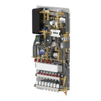
flamco Logotherm LogoThermic G2 UC Installation And Servicing Instruction (56 pages)
Thermostatically controlled heat interface units S-Line, 35 kW, M-Line, 46 kW
Brand:
flamco
| Category:
Plumbing Product
| Size: 16 MB
Table of Contents
Table of Contents
3
Safety Instructions
5
Intended Use
6
Use for Intended Purpose
6
Improper Use
7
Device Designation
7
Hazard Notes
7
What to Do in the Event of Breakdown or Leaks
8
Spare and Wear Parts
8
Requirements on Trained Engineers
8
Liability and Copyrights
9
Earth Bonding or Protective Earthing in Accordance with VDE
9
Functional Description
9
Logothermic Units
10
Technical Data
10
HIU Characteristics and Performance Parameters
10
Components and Hydraulic Diagram
12
Dimensions
14
Variants
14
Logothermic G2 with Domestic Hot Water Circulation (DWC)
14
Special Variants
16
Installation
17
SM/FM Mounting Rail with 7 Ball Valves (for MC/UC)
17
DN20 Ball Valves, Straight
18
Completing Stations
18
Optional Heat Meter Installation
18
Optional Water Meter Installation
19
Description of Individual Components and Setting Options
19
Hot Water Limiter
19
Dirt Traps
20
Zone Valve for Heating Circuit
21
Differential Pressure Regulator
22
Thermostatic Circulation Bridge
23
Thermostatic Control Valves
24
Thermostatic Domestic Water Mixing Valve, Flamcomix
25
Thermostatic Head, Type Rotherm II (Only for Stations with Mixed Heating Circuit)
26
Compact Mixing Circuit with High-Efficiency Pump (Only for MC Variant)
26
Secondary Bypass on Mixer (in Compact Mixing Circuit)
26
Heating Circuit Pump
27
Optional Accessories
28
Additional Static Heating Circuit (Only for MC Variants)
28
Additional Static Heating Circuit (for MC) and Simultaneous Heating Circuit Distribution
29
Heating Circuit Manifold for Surface-Mounted / Flush-Mounted Variants
30
Standard Manifold with 3 to 8 Heating Circuits for MC Variants
31
Underfloor Manifold with 3 to 12 Heating Circuits (Wide Version)
31
For MC Variants
32
For UC Variants
32
Terminal Strip for Underfloor Heating Circuit Manifolds
34
Covers and Installation Examples
36
Overview of Surface-Mounted Covers (SM)
36
Overview of Flush-Mounted Covers (FM)
37
FM Installation Examples
38
Long Version
38
Standard Version
39
Wide Version
40
Configuration Examples
41
Example I - LT M-Line with 12X UFH Manifold Via Side Mixer Group
41
Example II - LT + M-Line with DWC, Stat. HC and 12X UFH Manifold Via Connection Set
42
Example III - LT+, M-Line with DWC, Stat. HC and 8X UFH Manifold
43
Commissioning
44
Flushing and Filling
44
Initial Start-Up
44
Notes on Thermostatically Controlled Interface Stations
45
Maintenance and Service
45
Information Regarding Domestic Water Hardness
46
Maintenance Checklist
47
Pressure Loss Diagram
48
Spare Parts
50
Decommissioning, Dismantling, Disposal, Environmental Protection and Disposal of Electrical and Electronic Equipment
52
Advertisement
Advertisement
Related Products
flamco Logotherm LogoThermic G2 MC
flamco Logotherm LogoThermic G2
flamco LogoMatic G2
flamco Flextherm Eco G2 12E
flamco GPAIII Series
flamco GPA25-4 III
flamco GPA32-4 III
flamco GPA25-5 III
flamco GPA32-5 III
flamco GPA32-6 III
flamco Categories
Water Filtration Systems
Water Pump
Water System
Heating System
Control Unit
More flamco Manuals
Login
Sign In
OR
Sign in with Facebook
Sign in with Google
Upload manual
Upload from disk
Upload from URL