Table of Contents
Advertisement
Quick Links
Advertisement
Chapters
Table of Contents

Subscribe to Our Youtube Channel
Related Manuals for Farm King Allied 8420G


Summary of Contents for Farm King Allied 8420G
- Page 1 OPERATOR AND PARTS MANUAL Snowblower Model 7420, 8420, 8420G 092017 FK331...
-
Page 3: Table Of Contents
7420, 8420, 8420G Table Of Contents Manufacturer’s Statement: For technical reasons, Buhler Industries Inc. reserves the right to modify machinery design and specifications provided herein without any preliminary notice. Information provided herein is of descriptive nature. Performance quality may depend on soil fertility, applied agricultural techniques, weather conditions, and other factors. - Page 4 Three Point Hitch - 84” Models Hydraulic Spout Rotator Hand Crank Spout Rotator Hydraulic Spout Deflector Cylinder & Hose Kit PTO Shaft PTO Additional Components Specifications And Shipping Kit Numbers Specifications Shipping Kit And Bundle Numbers Hardware Torque Values Warranty Farm King Base Limited Warranty...
-
Page 5: Warranty Registration Form
Customer / Owner Signature: Remove this Warranty Registration Form from the Operator And Parts Manual. Make two copies of the form. Send original Warranty Registration Form to Farm King. Give one copy to the customer and the dealer will keep one copy. - Page 6 Warranty Registration Form - 7420, 8420, 8420G...
-
Page 7: Introduction
Farm King equipment. READ AND UNDERSTAND THIS OPERATOR AND PARTS MANUAL BEFORE OPERATING YOUR FARM KING EQUIPMENT. If you have any questions, see your Farm King dealer. This manual may illustrate options and accessories not installed on your Farm King equipment. - Page 8 Introduction - 7420, 8420, 8420G...
-
Page 9: Owner's Information
Model Number: and maintenance procedures. Serial Number: Farm King is continually working to improve its products. Farm King reserves the right to make The serial number plate (Item 1) [Figure 1] is any improvements or changes as deemed practical located on the top corner of the main frame. -
Page 10: Equipment Identification
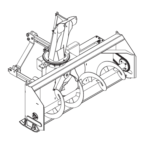
Introduction - 7420, 8420, 8420G Equipment Identification Component Location - Front View SPOUT DEFLECTOR HOIST MOUNT CHUTE CHAIN DRIVE FOUR BLADE AUGER SKID SHOE... -
Page 11: Component Location - Top View
Introduction - 7420, 8420, 8420G Component Location - Top View HYDRAULIC MOTOR MOUNT UPPER THREE-POINT MOUNTING PIN LOWER THREE-POINT PTO SHIELD MOUNTING PIN LOWER THREE-POINT MOUNTING PIN... - Page 12 Introduction - 7420, 8420, 8420G...
-
Page 13: Safety
Safety - 7420, 8420, 8420G Safety Safety Instructions Safe Operation is The Operator’s Responsibility Safe Operation Needs A Qualified Operator Use Safety Rules Safety Rules For Power Take-Off (PTO) Driven Equipment Machine Requirements And Capabilities Transport Safety Fire Prevention Maintenance Operation Starting Electrical... - Page 14 Safety - 7420, 8420, 8420G...
-
Page 15: Safety Instructions
• The written instructions from Farm King include the result in minor or moderate injury. It may also Warranty Registration, Dealer Inspection Report, be used to alert against unsafe practices. -
Page 16: Use Safety Rules
Safety - 7420, 8420, 8420G Use Safety Rules Safety Rules For Power Take-Off (PTO) Driven Equipment • Read and follow instructions in this manual and the tractor’s Operators Manual before operating. • Keep PTO shields and all guards in place. Replace damaged or missing shields and guards before •... -
Page 17: Machine Requirements And Capabilities
Safety - 7420, 8420, 8420G Machine Requirements And Capabilities Transport Safety • Fasten seat belt securely. If equipped with a foldable • Do not exceed 20 mph (32 kph). Reduce speed on Roll-Over Protective Structure (ROPS), only fasten rough roads and surfaces. seat belt when ROPS is up and locked. -
Page 18: Fire Prevention
Fueling components can cause a fire. Operation • The Farm King machine must be in good operating condition before use. • Check all of the items listed on the service schedule • Stop the engine and let it cool before adding fuel. No under the 8 hour column before operation. -
Page 19: Welding And Grinding
Safety - 7420, 8420, 8420G Welding And Grinding • Always clean the machine and equipment, disconnect the battery, and disconnect the wiring from the machine controls before welding. Cover rubber hoses, battery and all other flammable parts. Keep a fire extinguisher near the machine when welding. •... -
Page 20: Safety Signs (Decals)
Safety Signs (Decals) Follow the instructions on all the signs (decals) that are on the equipment. Replace any damaged signs (decals) and be sure they are in the correct locations. Equipment signs are available from your Farm King equipment dealer. -
Page 21: Equipment Decals And Signs
Safety - 7420, 8420, 8420G Equipment Decals And Signs Check and replace any worn, torn, missing, or hard to read decals on your equipment. Figure 4 OIL BATH GEARBOX 910823 (Item 1) [Figure 4] 817585 (Propeller Model Not Shown) 967388 (Item 3) [Figure 4] 815397 (Item 1) [Figure 4] 910626 (Item 2) [Figure 4]... -
Page 22: Safety Sign-Off Form
Untrained operators and failure to follow instructions can cause injury or death. Farm King follows the general Safety Standards specified by the American Society of Agricultural and Biological Engineers (ASABE) and the Occupational Safety and Health Administration (OSHA). Anyone who will be operating and / or maintaining the snowblower must read and clearly understand ALL Safety, Operating and Maintenance information presented in this manual. -
Page 23: Assembly
Assembly - 7420, 8420, 8420G Assembly Preparing For Assembly PTO Shield Hitch Assembly Discharge Spout & Deflector Hydraulic Spout Deflector (Option) Hydraulic Spout Rotator... - Page 24 Assembly - 7420, 8420, 8420G...
-
Page 25: Preparing For Assembly
• Check all the components for damage. If any • Wait for all moving parts to stop. components are damaged or missing, contact your Farm King dealer. Park the tractor / equipment on a flat level surface. Place all controls in neutral, engage the park brake,... -
Page 26: Pto Shield
Assembly - 7420, 8420, 8420G PTO Shield Hitch Assembly Figure 5 Figure 7 7420 & 8420 Models Bolt the PTO shield (Item 1) to the top of the gearbox assembly using 1/4” lock nuts, flat washers, and hex bolts (Item 2) [Figure 5]. Insert a 3/16”... - Page 27 Assembly - 7420, 8420, 8420G Figure 8 Figure 9 7420 Models Attach the top brackets of the left and right hitch arms (Item 1) by bolting a link pin bushing (Item 2) between the top brackets with a 3/4” x 4” bolt (Item 3) [Figure 8], flat washer, and lock nut.
-
Page 28: Discharge Spout & Deflector
Assembly - 7420, 8420, 8420G Discharge Spout & Deflector Figure 10 Figure 11 DISCHARGE 8420 & 8420G Models Attach the top brackets of the left and right hitch arms (Item 1) by bolting a link pin bushing (Item 2) between the top brackets with a 3/4” x 4” bolt (Item 3) [Figure 10], flat washer, and lock nut. -
Page 29: Hydraulic Spout Deflector (Option)
Assembly - 7420, 8420, 8420G Figure 12 Figure 13 Install the spout deflector (Item 1) on the discharge spout. Attach using one hinge pin (Item 2) [Figure 13] and retaining pins. Align the spout deflector adjustment rod (Item 3) on the mounts. Attach using two 1/2” x 1-1/2” clevis pins (Item 4) [Figure 13] and retaining pins. -
Page 30: Hydraulic Spout Rotator
Assembly - 7420, 8420, 8420G Hydraulic Spout Rotator The spout opening should face forward. The non- toothed smooth portion of the gear spout ring Figure 14 should face the side opposite of the motor mount. Attach the gear guard cover (Item 4) [Figure 14] above the motor using two 5/16”... -
Page 31: Operation
Operation - 7420, 8420, 8420G Operation Pre - Operation Checklist Entering The Operator’s Position Leaving The Operator’s Position Tractor Requirements Connecting The Snowblower To Tractor Connecting The PTO Driveline PTO Driveline Length Check PTO Driveline Bottoming Out Check Reducing The PTO Driveline Length PTO Driveline Engagement Check Connecting Hydraulic Hoses Disconnecting Hydraulic Hoses... - Page 32 Operation - 7420, 8420, 8420G...
-
Page 33: Pre - Operation Checklist
Operation - 7420, 8420, 8420G Pre - Operation Checklist Entering The Operator’s Position Before operating the snowblower for the first time Enter the operator’s position, start the engine, and and each time thereafter, check the following items: release the parking brake. Lubricate the equipment per the schedule outline in the Maintenance Section. -
Page 34: Connecting The Snowblower To Tractor
Operation - 7420, 8420, 8420G Connecting The Snowblower To WARNING Tractor Always inspect the tractor’s three-point hitch and snowblower three-point mounts before connecting. See the tractor’s owner’s manual. Move the tractor drawbar into the storage position or remove (if necessary) to prevent interference with snowblower operation. -
Page 35: Connecting The Pto Driveline
Operation - 7420, 8420, 8420G Connecting The PTO Driveline Figure 16 Stop the engine and leave the operator’s position (See “Leaving The Operator’s Position” Operator’s section). The PTO shafts are shipped with the slip Note: clutch disengaged. Engage the slip clutch. WARNING AVOID INJURY OR DEATH Warnings on the machine and in the manuals... -
Page 36: Pto Driveline Length Check
Operation - 7420, 8420, 8420G PTO Driveline Length Check PTO Driveline Bottoming Out Check Due to variations in distances between tractor PTO Stop the engine and leave the operator’s position shafts and implement input shafts, drivelines may (See “Leaving The Operator’s Position”... -
Page 37: Reducing The Pto Driveline Length
Operation - 7420, 8420, 8420G Reducing The PTO Driveline Length Figure 18 Stop the engine and leave the operator’s position IMPLEMENT (See “Leaving The Operator’s Position” in the PTO SHAFT Operation section). Make sure the PTO driveline and all rotating components have come to a complete stop before leaving the operator’s position. -
Page 38: Pto Driveline Engagement Check
(from Step 3), the PTO driveline does not have adequate engagement and should be replaced • Keep bystanders away. with a longer driveline. See your Farm King dealer for available PTO drivelines. • Keep hands, feet, clothing and long hair away. -
Page 39: Connecting Hydraulic Hoses
Operation - 7420, 8420, 8420G Connecting Hydraulic Hoses Disconnecting Hydraulic Hoses The snowblower may be equipped with the fol- Release pressure and pull the male couplers out to lowing hydraulic options, if applicable. disconnect. Hydraulic spout deflector WARNING 2. Hydraulic discharge chute Push couplers into female couplers on the tractor until they are fully engaged and locked. -
Page 40: Adjusting Skid Shoe Height
Operation - 7420, 8420, 8420G Adjusting Skid Shoe Height Skid Shoe Settings: Decrease Working Depth - Lower skid shoes. WARNING Increase Working Depth - Raise skid shoes. Figure 21 AVOID INJURY OR DEATH Before you leave the operator’s position: • Always park on a flat level surface. •... -
Page 41: Theory Of Operation
Operation - 7420, 8420, 8420G Theory Of Operation FAN BLADE CAUTION ROTATION • Read operator and parts manual before operating the implement. • Do not permit riders. • Keep all guards and shields in place. • Keep hands, feet, clothing and hair away from moving parts. -
Page 42: Transporting
Operation - 7420, 8420, 8420G Transporting Verify that the tractor / tow vehicle is approved for transporting the equipment and that the equipment Always comply with federal, state, local and is securely attached to the tractor / tow vehicle. provincial laws regarding the transport of farm Verify safety chain is installed and properly equipment on pubic roadways. -
Page 43: Maintenance
Maintenance - 7420, 8420, 8420G Maintenance Service Schedule Chart Lubrication Recommendations Locations Oil Bath Gearbox Chains And Fasteners Safety Sign (Decal) Installation Storage And Return To Service Storage Return To Service... - Page 44 Maintenance - 7420, 8420, 8420G...
-
Page 45: Service Schedule Chart
Maintenance - 7420, 8420, 8420G Service Schedule Chart WARNING Instructions are necessary before operating or servicing equipment. Read and understand the Operator And Parts Manual and safety signs (decals) on equipment. Follow warnings and instructions in the manuals when making repairs, adjustments or servicing. Check for correct function after adjustments, repairs or service. -
Page 46: Lubrication
Maintenance - 7420, 8420, 8420G Lubrication Locations Recommendations IMPORTANT Always use a good quality multi-purpose / lithium base grease when lubricating the equipment. Fluid such as engine oil, hydraulic fluid, • Always use a hand-held grease gun. coolants, grease, etc. must be disposed of •... - Page 47 Maintenance - 7420, 8420, 8420G Figure 23 Figure 25 8-10 Apply two pumps of grease to the guard bushings (Item 1) [Figure 23]. Apply grease to spout clamps and rings (Item 1) Apply eight to ten pumps of grease to the [Figure 25].
-
Page 48: Chains And Fasteners
Maintenance - 7420, 8420, 8420G Chains And Fasteners Oil Bath Gearbox Figure 27 Periodically check all bolts and fasteners for tightness. Figure 28 Check the main fan bolt (Item 1) [Figure 28] for 8420G Models tightness. Check the oil level using the plug on the lid (Item Check the tension in the drive chain (Item 2) [Figure 1) [Figure 27]. -
Page 49: Safety Sign (Decal) Installation
Maintenance - 7420, 8420, 8420G Safety Sign (Decal) Installation Storage And Return To Service Storage IMPORTANT Sometimes it may be necessary to store your Farm King snowblower for an extended period of time. Below is a list of items to perform before storage. When replacing safety signs (decals), the temperature must be above 10°... -
Page 50: Return To Service
Maintenance - 7420, 8420, 8420G Return To Service After the equipment has been in storage, it is necessary to follow a list of items to return the equipment to service. • Be sure all shields and guards are in place. •... -
Page 51: Parts Identification
Parts Identification - 7420, 8420, 8420G Parts Identification Main Components - Open Gearbox Main Components - Oil Bath Gearbox Oil Bath Gearbox - 84” Models Three Point Hitch - 74” Models Three Point Hitch - 84” Models Hydraulic Spout Rotator Hand Crank Spout Rotator Hydraulic Spout Deflector Cylinder &... - Page 52 Parts Identification - 7420, 8420, 8420G...
-
Page 53: Main Components - Open Gearbox
Parts Identification - 7420, 8420, 8420G Main Components - Open Gearbox Always give your dealer the Model, Color and Serial Number of your machine to assist them in ordering and obtaining the correct parts. Use the exploded view and tabular listing of the area of interest to exactly identify the required part. - Page 54 Parts Identification - 7420, 8420, 8420G Main Components - Open Gearbox 63 64 13 12 12 54 55 56 31 37...
- Page 55 Parts Identification - 7420, 8420, 8420G Main Components - Open Gearbox ITEM PART NUMBER DESCRIPTION QTY. 812362 5/16" LOCK NUT (PL) 812363 3/8" LOCK NUT (PL) 812364 1/2" LOCK NUT (PL) 812482 5/8" LOCK NUT (PL) 812639 WASHER 0.625 SAE FLAT BS PL 9812440 1 1/4"...
- Page 56 Parts Identification - 7420, 8420, 8420G Main Components - Open Gearbox ITEM PART NUMBER DESCRIPTION QTY. 84289 5/8" X 3" HEX BOLT GR.5 (PL) 84498 1/4" LOCK NUT (PL) 86170 3/8" X 1" HEX BOLT GR.5 (PL) 87553 1/2" X 1.75" HEX BOLT UNC GR5 (PL) 901940 DR SHFT KEY 5/16"...
-
Page 57: Main Components - Oil Bath Gearbox
Parts Identification - 7420, 8420, 8420G Main Components - Oil Bath Gearbox 32 17 13 16 31 29 13 16 35 29... - Page 58 Parts Identification - 7420, 8420, 8420G Main Components - Oil Bath Gearbox 55 56 46 47 48 12 11 11 29 35...
- Page 59 Parts Identification - 7420, 8420, 8420G Main Components - Oil Bath Gearbox ITEM PART NUMBER DESCRIPTION QTY. 812362 5/16" LOCK NUT (PL) 812363 3/8" LOCK NUT (PL) 812482 5/8" LOCK NUT (PL) 812639 WASHER 0.625 SAE FLAT BS PL BU50506 GBOX 965968 14GA X 7 1/2"...
- Page 60 Parts Identification - 7420, 8420, 8420G Main Components - Oil Bath Gearbox ITEM PART NUMBER DESCRIPTION QTY. 909277 MANUAL HOLDER 961637 BEARING FLANGE 62MS 965403 DRIVE SHAFT WELDT 965409 PTO SHLD WELDT 965814 3/8" X 3/8" X 4 1/4" FAN SHFT KEY 965818 1 1/4"...
-
Page 61: Oil Bath Gearbox - 84" Models
Parts Identification - 7420, 8420, 8420G Oil Bath Gearbox - 84” Models ITEM PART NUMBER DESCRIPTION BU50310 GEARBOX CASTING ONLY BU500089-3 PIPE PLUG BU50457 GEARBOX COVER BU500167-1 RELIEF VALVE BU50458 GEARBOX GASKET BU50508 CROSS SHAFT BU50502 PINION SHAFT BU50329 BEVEL GEAR - 1-1/2" BORE BU50331 BEVEL GEAR - 1-3/8"... -
Page 62: Three Point Hitch - 74" Models
Parts Identification - 7420, 8420, 8420G Three Point Hitch - 74” Models ITEM PART NUMBER DESCRIPTION QTY. 815263 74" HITCH LHS 815264 74" HITCH RHS 816131 3/4" DIA. X 4.25" LG CLEV PIN 816151 CLEVIS PIN 0.88" DIA. X 3-3/4" LG 812365 3/4"... -
Page 63: Three Point Hitch - 84" Models
Parts Identification - 7420, 8420, 8420G Three Point Hitch - 84” Models ITEM PART NUMBER DESCRIPTION QTY. 816131 3/4" DIA. X 4.25" LG CLEV PIN 812365 3/4" LOCK NUT (PL) 84050 3/4" FLAT WASHER (PL) 84336 3/4" X 4" HEX BOLT (PL) 907220 3/16"W X 2"... -
Page 64: Hydraulic Spout Rotator
Parts Identification - 7420, 8420, 8420G Hydraulic Spout Rotator ITEM PART NUMBER DESCRIPTION QTY. 816682 PTO MODELS HYD SPOUT ROTATION HOSE 816840 GEAR GUARD WELDT 817014 PINION GEAR 14 TEETH 818903 ASSEMBLY - MOTOR & MANIFOLD 907590 SPT HOSE HLDR WELDT 812026 5/16"... -
Page 65: Hand Crank Spout Rotator
Parts Identification - 7420, 8420, 8420G Hand Crank Spout Rotator ITEM PART NUMBER DESCRIPTION QTY. 81344 LOCK NUT (NYLON) 0.375 NC 815250 P-CLAMP FOR 3/4 OD, .406 HOLE 81531 BOLT HEX 0.25NC X 2.00 GR5 PL 81570 3/8" STD FLAT WASH (PL) 816893 HORTIZONAL BRACE 816894... -
Page 66: Hydraulic Spout Deflector Cylinder & Hose Kit
Parts Identification - 7420, 8420, 8420G Hydraulic Spout Deflector Cylinder & Hose Kit PART NUMBER DESCRIPTION 24930M 1-3/4" ID X 5" STROKE CYLINDER 116983 HOSE 3/8 X 120 C/W FITTINGS 960913 CLEVIS PIN 1/2 X 1.8125 (PL) 9812430 COTTER PIN 1/8 X 1.00 (PL) 811918 ELBOW 90 9/16 SWMORB X 9/16 MJIC 24930M... -
Page 67: Pto Shaft
Parts Identification - 7420, 8420, 8420G PTO Shaft ITEM PART NUMBER DESCRIPTION 817804 YOKE W/QL BALL TYPE 817805 YOKE W/TUBE & SLEEVE 925293 CROSS KIT W/ GREASE NIPPLE 817774 CHAIN 817807 SHAFT SHIELD 817808 RETAINER 817809 RETAINER 818270 SHEAR BOLT CLUTCH 925305 INBOUND YOKE - INNER TUBE 818268... -
Page 68: Pto Additional Components
Parts Identification - 7420, 8420, 8420G PTO Additional Components PTO ADDITIONAL HARDWARE PTO SHIELD HARDWARE ITEM PART NUMBER DESCRIPTION QTY. 812364 1/2" LOCK NUT (PL) 812624 1/4" FLAT WASHER PL 81523 1/4" X 1/2" HEX BOLT (PL) 81627 1/2" X 3" HEX BOLT (PL) 84498 1/4"... -
Page 69: Specifications And Shipping Kit Numbers
Specifications And Shipping Kit Numbers - 7420, 8420, 8420G Specifications And Shipping Kit Numbers Specifications Shipping Kit And Bundle Numbers Hardware Torque Values Metric Chart Imperial Chart... - Page 70 Specifications And Shipping Kit Numbers - 7420, 8420, 8420G...
-
Page 71: Specifications
Specifications And Shipping Kit Numbers - 7420, 8420, 8420G Specifications Shipping Kit And Bundle Numbers The following is a list of Kit Numbers for this MODEL 7420 8420 8420G product and the Bundle Numbers, Descriptions, and Quantities for each Kit. Cutting Width 74”... -
Page 72: Hardware Torque Values
Specifications And Shipping Kit Numbers - 7420, 8420, 8420G Hardware Torque Values Metric Chart... -
Page 73: Imperial Chart
Specifications And Shipping Kit Numbers - 7420, 8420, 8420G Imperial Chart... - Page 74 Specifications And Shipping Kit Numbers - 7420, 8420, 8420G...
-
Page 75: Warranty
Warranty - 7420, 8420, 8420G Warranty Farm King Base Limited Warranty Repair Parts Limited Warranty What Is Not Covered Authorized Dealer And Labor Costs Warranty Requirements EXCLUSIVE EFFECT OF WARRANTY AND LIMITATION OF LIABILITY... - Page 76 Warranty - 7420, 8420, 8420G...
-
Page 77: Farm King Base Limited Warranty
If Farm King determines that it will pay labor costs for warranty work, it will do so by issuing a credit to the dealer’s or distributor’s account. - Page 78 Corrections of defects and improper workmanship in the manner, and for the applicable time periods, provided for herein shall constitute fulfillment of all responsibilities of Farm King to the purchaser, and Farm King shall not be liable in negligence, contract, or on any other basis with respect to the subject equipment.
- Page 80 www.farm-king.com 1330 43rd Street North Fargo, ND, 58102 Toll Free: 888.524.1004 E-mail: info@buhler.com www.farm-king.com Equipment shown is subject to change without notice. ©2017 Buhler Trading Inc. Printed in USA TSX:BUI a division of Buhler Industries Inc.
Need help?
Do you have a question about the Allied 8420G and is the answer not in the manual?
Questions and answers