SMC Networks TigerSwitch SMC8126L2 Installation Manual
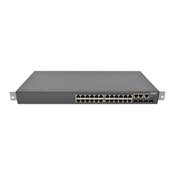
Tigerswitch 10/100/1000 26-port gigabit managed switch
Hide thumbs
Also See for TigerSwitch SMC8126L2:
- Management manual (502 pages) ,
- Technical specifications (2 pages) ,
- Technical specifications (2 pages)

Subscribe to Our Youtube Channel
Related Manuals for SMC Networks TigerSwitch SMC8126L2


Summary of Contents for SMC Networks TigerSwitch SMC8126L2
-
Page 1: Installation Guide
INSTALLATION GUIDE SMC8126L2 TigerSwitch 10/100/1000 26-Port Gigabit Managed Switch... - Page 3 TigerSwitch 10/100/1000 Installation Guide From SMC’s Tiger line of feature-rich workgroup LAN solutions 20 Mason Irvine, CA 92618 Phone: (949) 679-8000 July 2007 Pub. # 150200062800A E072007-AP-R01...
- Page 4 No license is granted by implication or otherwise under any patent or patent rights of SMC. SMC reserves the right to change specifications at any time without notice.
-
Page 5: Japan Vcci Class A
Compliances and Safety Warnings FCC - Class A This equipment has been tested and found to comply with the limits for a Class A digital device, pursuant to part 15 of the FCC Rules. These limits are designed to provide reasonable protection against harmful interference when the equipment is operated in a commercial environment. -
Page 6: Ce Mark Declaration Of Conformance For Emi And Safety (Eec)
CE Mark Declaration of Conformance for EMI and Safety (EEC) This information technology equipment complies with the requirements of the Council Directive 89/336/EEC on the Approximation of the laws of the Member States relating to Electromagnetic Compatibility and 73/23/EEC for electrical equipment used within certain voltage limits and the Amendment Directive 93/68/EEC. -
Page 7: Safety Compliance
製品本体に同梱された電源コードセットを利用し、他製品 の電源コードセットを使用しないで下さい。 Power Cord Safety Please read the following safety information carefully before installing the switch: WARNING: Installation and removal of the unit must be carried out by qualified personnel only. • The unit must be connected to an earthed (grounded) outlet to comply with international safety standards. - Page 8 The mains cord must be <HAR> or <BASEC> marked and be of type HO3VVF3GO.75 (minimum). IEC-320 receptacle. Veuillez lire à fond l'information de la sécurité suivante avant d'installer le Switch: AVERTISSEMENT: L’installation et la dépose de ce groupe doivent être confiés à un personnel qualifié.
- Page 9 France et Pérou uniquement: Ce groupe ne peut pas être alimenté par un dispositif à impédance à la terre. Si vos alimentations sont du type impédance à la terre, ce groupe doit être alimenté par une tension de 230 V (2 P+T) par le biais d’un transformateur d’isolement à rapport 1:1, avec un point secondaire de connexion portant l’appellation Neutre et avec raccordement direct à...
-
Page 10: Warnings And Cautionary Messages
Warning: This switch uses lasers to transmit signals over fiber optic cable. The lasers are compliant with the requirements of a Class 1 Laser Product and are inherently eye safe in normal operation. However, you should never look directly at a transmit port when it is powered on. -
Page 11: Related Publications
You should be familiar with switching and networking concepts. Zielgruppe Dieser Anleitung ist fuer Systemadministratoren mit Erfahrung im Netzwerkmangement. Sie sollten mit Switch- und Netzwerkkonzepten vertraut sein. Related Publications The following publication gives specific information on how to operate and use the... - Page 12 viii...
-
Page 13: Table Of Contents
Introduction to Switching Application Examples Collapsed Backbone Network Aggregation Plan Remote Connections with Fiber Cable Making VLAN Connections Application Notes Chapter 3: Installing the Switch Selecting a Site Ethernet Cabling Equipment Checklist Package Contents Optional Rack-Mounting Equipment Mounting Rack Mounting... - Page 14 1000 Mbps Gigabit Ethernet Collision Domain 100 Mbps Fast Ethernet Collision Domain 10 Mbps Ethernet Collision Domain Cable Labeling and Connection Records Appendix A: Troubleshooting Diagnosing Switch Indicators Power and Cooling Problems Installation In-Band Access Appendix B: Cables Twisted-Pair Cable and Pin Assignments...
- Page 15 Contents Appendix D: Ordering Information Glossary Index...
- Page 16 Contents...
- Page 17 Tables Table 1-1 Port Status LEDs Table 1-2 System Status LEDs Table 3-1 Serial Cable Wiring Table 4-1 Maximum 1000BASE-T Gigabit Ethernet Cable Length Table 4-2 Maximum 1000BASE-SX Gigabit Ethernet Cable Length Table 4-3 Maximum 1000BASE-LX Gigabit Ethernet Cable Length Table 4-4 Maximum 1000BASE-ZX Gigabit Ethernet Cable Length Table 4-5...
- Page 18 Figure 2-4 Making VLAN Connections Figure 3-1 RJ-45 Connections Figure 3-2 Attaching the Brackets Figure 3-3 Installing the Switch in a Rack Figure 3-4 Attaching the Adhesive Feet Figure 3-5 Inserting an SFP Transceiver into a Slot Figure 3-6 Power Socket...
-
Page 19: Chapter 1: Introduction
The switch can easily tame your network with full support for Spanning Tree Protocol, Multicast Switching, and Virtual LANs. It brings order to poorly performing networks by segregating them into separate broadcast domains with IEEE 802.1Q compliant VLANs, empowers multimedia applications with multicast switching and CoS services. -
Page 20: Switch Architecture
It also includes a management agent that allows you to configure or monitor the switch using its embedded management software, or via SNMP applications. To manage this switch, you can make a direct connection to the console port (out-of-band), or you can manage the switch through a network connection (in-band) using Telnet, the on-board web agent, or SNMP-based network management software. -
Page 21: Description Of Hardware
The SMC8126L2 contains 26 RJ-45 ports that operate at 10 Mbps or 100 Mbps, half or full duplex, or at 1000 Mbps, full duplex. Because all ports on this switch support automatic MDI/MDI-X operation, you can use straight-through cables for all network connections to PCs or servers, or to other switches or hubs. -
Page 22: Table 1-1 Port Status Leds
Introduction Label Color Link/Activity/ On/Flashing Amber Speed On/Flashing Green Port 21/22/23/ Green Port 25/26 On/Flashing Amber On/Flashing Green Condition Power Green Diag Flashing Green/ Amber Green Amber Table 1-1 Port Status LEDs Description Port has a valid link at 10 or 100 Mbps. Flashing indicates activity. Port has a valid link at 1000 Mbps. -
Page 23: Power Supply Socket
Power Supply Socket The power socket is on the rear panel. The standard power socket is for the AC power cord. Features and Benefits Connectivity • 26 10/100/1000 Mbps ports for easy Gigabit Ethernet integration and for protection of your investment in legacy LAN equipment. •... -
Page 24: Management
Introduction Management • “At-a-glance” LEDs for easy troubleshooting • Network management agent: - Manages switch in-band or out-of-band - Supports console, Telnet, SSH, SNMP v1/v2c/v3, RMON (4 groups) and web-based interface... -
Page 25: Chapter 2: Network Planning
When networks are based on repeater (hub) technology, the distance between end stations is limited by a maximum hop count. However, a switch turns the hop count back to zero. So subdividing the network into smaller and more manageable segments, and linking them to the larger network by means of a switch, removes this limitation. -
Page 26: Application Examples
When the time comes for further expansion, just connect to another hub or switch using one of the Gigabit Ethernet ports built into the front panel, or a Gigabit Ethernet port on a plug-in SFP transceiver. -
Page 27: Network Aggregation Plan
Application Examples Network Aggregation Plan With 26 parallel bridging ports (i.e., 26 distinct collision domains), a switch can collapse a complex network down into a single efficient bridged node, increasing overall bandwidth and throughput. In the figure below, the 10/100/1000BASE-T ports are providing 1000 Mbps connectivity through Layer 2 switches. -
Page 28: Remote Connections With Fiber Cable
1000BASE-SX (MMF) link can connect to a site up to 550 meters away, a 1000BASE-LX (SMF) link up to 5 km, and a 1000BASE-ZX link up to 100 km. This allows a switch to serve as a collapsed backbone, providing direct connectivity for a widespread LAN. -
Page 29: Making Vlan Connections
Finance Marketing VLAN 3 VLAN 4 Note: When connecting to a switch that does not support IEEE 802.1Q VLAN tags, use untagged ports. Untagged Ports VLAN unaware switch... -
Page 30: Application Notes
Application Notes Full-duplex operation only applies to point-to-point access (such as when a switch is attached to a workstation, server or another switch). When the switch is connected to a hub, both devices must operate in half-duplex mode. For network applications that require routing between dissimilar network types, you can attach these switches directly to a multi-protocol router. -
Page 31: Chapter 3: Installing The Switch
100BASE-TX, and Category 5, 5e or 6 for 1000BASE-T. • Protection from radio frequency interference emissions • Electrical surge suppression • Separation of electrical wires (switch related or other) and electromagnetic fields from data based network wiring • Safe connections with no damaged cables, connectors or shields... -
Page 32: Equipment Checklist
Installing the Switch Equipment Checklist After unpacking the switch, check the contents to be sure you have received all the components. Then, before beginning the installation, be sure you have all other necessary installation equipment. Package Contents • TigerSwitch 10/100/1000, SMC8126L2 •... -
Page 33: Mounting
Mounting This switch can be mounted in a standard 19-inch equipment rack or on a desktop or shelf. Mounting instructions for each type of site follow. Rack Mounting Before rack mounting the switch, pay particular attention to the following factors: •... -
Page 34: Desktop Or Shelf Mounting
Mount the device in the rack, using four rack-mounting screws (not provided). Figure 3-3 Installing the Switch in a Rack If installing a single switch only, turn to “Connecting to a Power Source” at the end of this chapter. If installing multiple switches, mount them in the rack, one below the other, in any order. -
Page 35: Installing An Optional Sfp Transceiver
If installing a single switch only, go to “Connecting to a Power Source” at the end of this chapter. If installing multiple switches, attach four adhesive feet to each one. Place each device squarely on top of the one below, in any order. -
Page 36: Connecting To A Power Source
LED is on. If not, check that the power cable is correctly plugged in. Connecting to the Console Port The RJ-45 serial port on the switch’s front panel is used to connect to the switch for out-of-band console configuration. The on-board configuration program can be accessed from a terminal or a PC running a terminal emulation program. -
Page 37: Wiring Map For Serial Cable
Wiring Map for Serial Cable Switch’s 8-Pin Serial Port 6 RXD (receive data) 3 TXD (transmit data) 5 SGND (signal ground) ------------------------------ 5 SGND (signal ground) No other pins are used. The serial port’s configuration requirements are as follows: • Default Baud rate—9,600 bps •... - Page 38 Installing the Switch...
-
Page 39: Chapter 4: Making Network Connections
Category 5 or better for 100BASE-TX connections, and Category 3 or better for 10BASE-T connections. Cabling Guidelines The RJ-45 ports on the switch support automatic MDI/MDI-X pinout configuration, so you can use standard straight-through twisted-pair cables to connect to any other network device (PCs, servers, switches, routers, or hubs). -
Page 40: Connecting To Pcs, Servers, Hubs And Switches
Figure 4-1 Making Twisted-Pair Connections If the device is a PC card and the switch is in the wiring closet, attach the other end of the cable segment to a modular wall outlet that is connected to the wiring closet. -
Page 41: Fiber Optic Sfp Devices
Network Switch Figure 4-2 Network Wiring Connections Fiber Optic SFP Devices An optional Gigabit SFP transceiver (1000BASE-SX, 1000BASE-LX or 1000BASE-ZX) can be used for a backbone connection between switches, or for connecting to a high-speed server. Each single-mode fiber port requires 9/125 micron single-mode fiber optic cable with an LC connector at both ends. -
Page 42: Connectivity Rules
Connect one end of the cable to the LC port on the switch and the other end to the LC port on the other device. Since LC connectors are keyed, the cable can be attached in only one orientation. -
Page 43: 1000Base-T Cable Requirements
1000BASE-T Cable Requirements All Category 5 UTP cables that are used for 100BASE-TX connections should also work for 1000BASE-T, providing that all four wire pairs are connected. However, it is recommended that for all critical connections, or any new cable installations, Category 5e (enhanced Category 5) or Category 6 cable should be used. -
Page 44: 10 Mbps Ethernet Collision Domain
For each piece of equipment, identify the devices to which it is connected. • Note the length of each cable and the maximum cable length supported by the switch ports. • For ease of understanding, use a location-based key when assigning prefixes to your cable labeling. -
Page 45: Appendix A: Troubleshooting
• If the condition does not clear, contact your local dealer for assistance. • Verify that the switch and attached device are powered on. • Be sure the cable is plugged into both the switch and corresponding device. • Verify that the proper cable type is used and its length does not exceed specified limits. -
Page 46: In-Band Access
IP address. Also, be sure the port through which you are connecting to the switch has not been disabled. If it has not been disabled, then check the network cabling that runs between your remote location and the switch. -
Page 47: Appendix B: Cables
Category 5 cable for 100 Mbps connections. Also be sure that the length of any twisted-pair connection does not exceed 100 meters (328 feet). The RJ-45 ports on the switch base unit support automatic MDI/MDI-X operation, so you can use straight-through cables for all network connections to PCs or servers, or to other switches or hubs. -
Page 48: Straight-Through Wiring
Cables Table B-1 10/100BASE-TX MDI and MDI-X Port Pinouts Transmit Data plus (TD+) Transmit Data minus (TD-) Receive Data plus (RD+) Receive Data minus (RD-) 4,5,7,8 Not used Note: The “+” and “-” signs represent the polarity of the wires that make up each wire pair. -
Page 49: 1000Base-T Pin Assignments
You must connect all four wire pairs as shown in the following diagram to support Gigabit Ethernet connections. EIA/TIA 568B RJ-45 Wiring Standard End A 1000BASE-T Pin Assignments All 1000BASE-T ports support automatic MDI/MDI-X operation, so you can use straight-through cables for all network connections to PCs or servers, or to other switches or hubs. -
Page 50: Cable Testing For Existing Category 5 Cable
Cables Cable Testing for Existing Category 5 Cable Installed Category 5 cabling must pass tests for Attenuation, Near-End Crosstalk (NEXT), and Far-End Crosstalk (FEXT). This cable testing information is specified in the ANSI/TIA/EIA-TSB-67 standard. Additionally, cables must also pass test parameters for Return Loss and Equal-Level Far-End Crosstalk (ELFEXT). -
Page 51: Appendix C: Specifications
Appendix C: Specifications Physical Characteristics Ports 22 10/100/1000BASE-T, with auto-negotiation 4 10/100/1000BASE-T shared with 4 SFP transceiver slots Network Interface Ports 1-26: RJ-45 connector, auto MDI/X 10BASE-T: RJ-45 (100-ohm, UTP cable; Category 3 or better) 100BASE-TX: RJ-45 (100-ohm, UTP cable; Category 5 or better) 1000BASE-T: RJ-45 (100-ohm, UTP or STP cable;... -
Page 52: Switch Features
Internal, auto-ranging transformer: 100 to 240 VAC, 50 to 60 Hz Power Consumption 38 Watts Maximum Current 0.25 A @ 115 VAC 0.12 A @ 230 VAC Switch Features Forwarding Mode Store-and-forward Throughput Wire speed Flow Control Full Duplex: IEEE 802.3x... -
Page 53: Compliances
Ethernet, Fast Ethernet, Gigabit Ethernet Full-duplex flow control IEEE 802.1D Spanning Tree Protocol IEEE 802.1w Rapid Spanning Tree Protocol IEEE 802.1s Multiple Spanning Tree Protocol IEEE 802.1Q Virtual LAN ISO/IEC 8802-3 CSMA/CD Compliances CE Mark Emissions FCC Class A Industry Canada Class A EN55022 (CISPR 22) Class A EN 61000-3-2/3 VCCI Class A... - Page 54 Specifications...
-
Page 55: Appendix D: Ordering Information
Table D-1 TIgerSwitch 10/100/1000 Products and Accessories Product Number SMC8126L2 SMCBGSLCX1 SMCBGLLCX1 SMCBGZLCX1 Description 26-port Gigabit managed switch Single-port 1000BASE-SX Small Form Pluggable (SFP) mini-GBIC transceiver Single-port 1000BASE-LX Small Form Pluggable (SFP) mini-GBIC transceiver Single-port 1000BASE-ZX Small Form Pluggable (SFP) mini-GBIC transceiver... - Page 56 Ordering Information...
- Page 57 Glossary 10BASE-T IEEE 802.3 specification for 10 Mbps Ethernet over two pairs of Category 3, 4, or 5 UTP cable. 100BASE-TX IEEE 802.3u specification for 100 Mbps Fast Ethernet over two pairs of Category 5 or better UTP cable. 1000BASE-LX IEEE 802.3z specification for Gigabit Ethernet over two strands of 50/125, 62.5/125 or 9/125 micron core fiber cable.
- Page 58 Glossary CSMA/CD CSMA/CD (Carrier Sense Multiple Access/Collision Detect) is the communication method employed by Ethernet, Fast Ethernet, or Gigabit Ethernet. End Station A workstation, server, or other device that does not forward traffic. Ethernet A network communication system developed and standardized by DEC, Intel, and Xerox, using baseband transmission, CSMA/CD access, logical bus topology, and coaxial cable.
- Page 59 Glossary IEEE 802.3z Defines CSMA/CD access method and physical layer specifications for 1000BASE Gigabit Ethernet. (Now incorporated in IEEE 802.3-2005.) LAN Segment Separate LAN or collision domain. Light emitting diode used for monitoring a device or network condition. Local Area Network (LAN) A group of interconnected computer and support devices.
- Page 60 Glossary Transmission Control Protocol/Internet Protocol (TCP/IP) Protocol suite that includes TCP as the primary transport protocol, and IP as the network layer protocol. Unshielded twisted-pair cable. Virtual LAN (VLAN) A Virtual LAN is a collection of network nodes that share the same collision domain regardless of their physical location or connection point in the network.
- Page 61 IEEE 802.3ae 10 Gigabit Ethernet 1-5 IEEE 802.3u Fast Ethernet 1-5 IEEE 802.3z Gigabit Ethernet 1-5 indicators, LED 1-3 installation connecting devices to the switch 4-2 desktop or shelf mounting 3-4 port connections 4-1 power requirements 3-1 problems A-1 RPU in racks 3-4...
- Page 62 Index management agent 1-2 features 1-6, C-2, C-3 out-of-band 1-2 SNMP 1-2 web-based 1-2 mounting the switch on a desktop or shelf 3-4 multimode fiber optic cables 4-3 network connections 4-1 examples 2-2 ordering information D-1 out-of-band management 1-2 package contents 3-2...
- Page 64 Technische ondersteuningsinformatie beschikbaar op www.smc.com PORTUGUES Informações sobre Suporte Técnico em www.smc.com SWEDISH Information om Teknisk Support finns tillgängligt på www.smc.com INTERNET E-mail address: techsupport@smc.com Driver updates http://www.smc.com/ index.cfm?action=tech_support_drivers_downloads World Wide Web http://www.smc.com/ 20 Mason • Irvine, CA 92618 • Phn: 949-679-8000 • www.smc.com...
Need help?
Do you have a question about the TigerSwitch SMC8126L2 and is the answer not in the manual?
Questions and answers