
Related Manuals for Allice Messtechnik Testec TT-SI 9101


Summary of Contents for Allice Messtechnik Testec TT-SI 9101
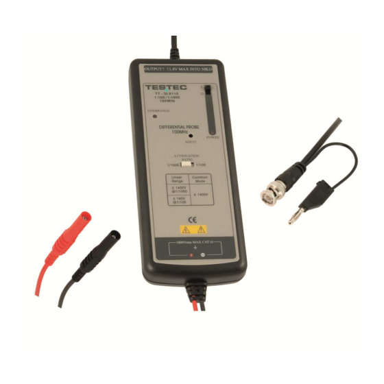
- Page 1 Allice Messtechnik GmbH INSTRUCTION MANUAL TT-SI 9101 100MHz Active Differential Probe...
- Page 2 Allice Messtechnik GmbH These probe is in compliance with IEC-61010-031 CAT III, Pollution Degree 2 1. Safety Terms and Symbols Terms appear in this manual: ___________________________________________________ WARNING. Warning statements identify conditions or practice that could result in injury or loss life.
- Page 3 Allice Messtechnik GmbH Must be Grounded This probe is grounded with the shell of BNC connector and an auxiliary grounding terminal, through the grounding conductor of the power cord of the measurement instrument. Before making connections to the input leads of this probe, ensure that the output BNC connector...
- Page 4 Allice Messtechnik GmbH 4. Installation a. Simply plug-in the BNC output connector to the vertical input of a general purposed oscilloscope or other measurement instrument, and connects the auxiliary grounding terminal to a proper ground. The measurement instrument must have a ground referenced.
- Page 5 Allice Messtechnik GmbH 6. Available Power Sources 4 x AA batteries Mains adaptor (6VDC/60mA or regulated 9VDC/40mA), ® ® Lemo Power Cord, for oscilloscopes with power output - Lemo connector. ® ® d. Probus Power Cord, for oscilloscopes with power output - Probus connector.
- Page 6 Allice Messtechnik GmbH 9. Specifications TT-SI 9101 Bandwidth DC to 100MHz (-3dB) Attenuation Ratio 1:10 / 1:100 Accuracy ±2% Rise Time 3,5ns Ω Input Impedance // 7pF each side to ground Input Voltage 1:10 ±70V (DC+peak AC) or 70Vrms - Differential Range 1:100 ±700V (DC+peak AC) or 700Vrms...
- Page 7 Allice Messtechnik GmbH 10. Derating Curve The derating curve of the absolute maximum input voltage in common mode is shown as follows. 11. Offset Adjustment If the offset voltage is too large, short the input leads and turn the adjust variable resistor (DC voltage adjustment) which you find in the hole of the panel by using a flat-head screwdriver until the offset voltage is lowest.
- Page 8 Fax: +49(0)69-67724-582 info@allice.de www.allice.de © 2018 Allice Messtechnik GmbH – Alle Rechte vorbehalten. © 2018 Allice Messtechnik GmbH – All rights reserved Verwendete Warenzeichen und Schutzrechte sind Eigentum der jeweiligen Hersteller. Logos and company names listed are trademarks or trade names of their respective owners.
Need help?
Do you have a question about the Testec TT-SI 9101 and is the answer not in the manual?
Questions and answers