
Related Manuals for Allice Messtechnik R&S ZND


Summary of Contents for Allice Messtechnik R&S ZND
- Page 1 Allice Messtechnik GmbH ® R&S Vector Network Analyzers User Manual (;×íÇ2) 1173955702 Version 61...
- Page 2 Allice Messtechnik GmbH ® This manual describes the R&S ZND (2 ports, 9 kHz to 4.5 GHz, unidirectional, N connectors), order no. 1328.5170K92 and its options. Hardware Options ● ® R&S ZND-B7 "High Output Power", order no. 1338.1578.02 ●...
-
Page 3: Table Of Contents
Allice Messtechnik GmbH ® Contents R&S Contents 1 Safety and regulatory information............13 Safety instructions......................13 Warning messages in the documentation..............15 Korea certification class A..................16 2 Welcome to the R&S ZND..............17 What's new in firmware version 3.40.................17 Documentation overview....................20 2.2.1... - Page 4 Allice Messtechnik GmbH ® Contents R&S Operating the instrument................... 40 3.3.1 Manual operation......................40 3.3.2 Control elements of the application window..............45 3.3.3 Working with dialogs..................... 51 3.3.4 Handling diagrams, traces, and markers..............52 3.3.5 Entering data.........................56 3.3.6 Scaling diagrams......................59 Performing measurements..................65...
- Page 5 Allice Messtechnik GmbH ® Contents R&S 4.4.3 Memory-mapped trace data transfer................143 Calibration......................... 145 4.5.1 Calibration types......................146 4.5.2 Calibration standards and calibration kits..............157 4.5.3 Calibration pool......................163 4.5.4 Calibration labels......................163 4.5.5 Automatic calibration....................164 4.5.6 Scalar power calibration....................175 4.5.7 Parallel calibration of multiple channels..............
- Page 6 Allice Messtechnik GmbH ® Contents R&S 4.7.20 External switch matrices..................... 220 4.7.21 External DLLs......................226 4.7.22 R&S ZNXSIM......................228 5 GUI reference..................232 Function Keys and Softtools................... 232 Meas softtool......................234 5.2.1 S-Params tab......................235 5.2.2 Ratios tab........................244 5.2.3 Wave tab........................247 5.2.4...
- Page 7 Allice Messtechnik GmbH ® Contents R&S Lines softtool......................316 5.6.1 Limit Test tab....................... 316 5.6.2 Ripple Test tab......................325 5.6.3 Circle Test tab......................329 5.6.4 Display Circle tab......................333 5.6.5 Horiz. Line tab......................334 Marker softtool......................335 5.7.1 Markers tab......................... 335 5.7.2...
- Page 8 Allice Messtechnik GmbH ® Contents R&S 5.11.4 Use Cal tab......................... 434 5.12 Channel Config softtool....................439 5.12.1 Channels tab....................... 440 5.12.2 Port Config tab......................443 5.12.3 Mode tab........................448 5.12.4 Pwr Cal Settings tab....................449 5.13 Offset Embed softtool....................449 5.13.1 Offset Embed dock widget..................449 5.13.2...
- Page 9 Allice Messtechnik GmbH ® Contents R&S 5.16.4 View Bar tab........................ 537 5.16.5 Touchscreen tab......................538 5.17 Setup softtool......................539 5.17.1 Setup tab........................539 5.17.2 Freq. Ref. tab......................564 5.17.3 Remote Settings tab....................565 5.17.4 External Devices tab....................568 5.17.5 External Ports tab......................574 5.18...
- Page 10 Allice Messtechnik GmbH ® Contents R&S 6.5.1 Overview of status registers..................609 6.5.2 Structure of a SCPI status register................609 6.5.3 Contents of the status registers...................611 6.5.4 Application of the status reporting system..............617 6.5.5 Reset values of the status reporting system............... 620 7 Command reference................
- Page 11 Allice Messtechnik GmbH ® Contents R&S 7.4.1 SNMP/REST commands................... 1100 7.4.2 System information commands................. 1104 7.4.3 Device tags commands..................... 1114 7.4.4 Utilization commands....................1115 7.4.5 Service date commands.................... 1118 R&S ZVR/ZVABT compatible commands.............. 1120 8 Programming examples..............1143 Basic tasks.......................1143 8.1.1 Typical stages of a remote control program..............
- Page 12 Allice Messtechnik GmbH ® Contents R&S 12.1.2 Remote operation in a LAN..................1186 12.2 System recovery......................1190 12.3 Interfaces and connectors..................1190 12.3.1 Rear panel connectors....................1190 12.3.2 LAN interface......................1192 12.3.3 GPIB interface......................1193 12.3.4 Handler I/O (universal interface)................1196 12.4 Showroom mode..................... 1204 12.5...
-
Page 13: Safety And Regulatory Information
Allice Messtechnik GmbH ® Safety and regulatory information R&S Safety instructions 1 Safety and regulatory information The product documentation helps you use the product safely and efficiently. Follow the instructions provided here and in the following chapters. Intended use The product is intended for the development, production and verification of electronic components and devices in industrial, administrative, and laboratory environments. - Page 14 Allice Messtechnik GmbH ® Safety and regulatory information R&S Safety instructions Choosing the operating site Only use the product indoors. The product casing is not waterproof. Water that enters can electrically connect the casing with live parts, which can lead to electric shock, serious personal injury or death if you touch the casing.
-
Page 15: Warning Messages In The Documentation
Allice Messtechnik GmbH ® Safety and regulatory information R&S Warning messages in the documentation ● Only connect the product to a power source with a fuse protection of maximum 20 A. ● Ensure that you can disconnect the product from the power source at any time. -
Page 16: Korea Certification Class A
Allice Messtechnik GmbH ® Safety and regulatory information R&S Korea certification class A 1.3 Korea certification class A 이 기기는 업무용(A급) 전자파 적합기기로서 판매자 또는 사용자는 이 점을 주의하시기 바라며, 가정외의 지역에서 사용하는 것을 목적으로 합니다. User Manual 1173.9557.02 ─ 61... -
Page 17: Welcome To The R&S Znd
Allice Messtechnik GmbH ® Welcome to the R&S ZND R&S What's new in firmware version 3.40 2 Welcome to the R&S ZND This manual is intended to provide you with all information that is necessary for setup, manual and remote control of the R&S ZND. - Page 18 Allice Messtechnik GmbH ® Welcome to the R&S ZND R&S What's new in firmware version 3.40 New remote control features ● Deembedding tools ISD, SFD, and EZD: – New commands CALCulate:FMODel:DIRectory, CALCulate:FMODel: DIRectory:DEFault, and CALCulate:FMODel:DIRectory:DEFault: for managing the common working directory CLEar –...
- Page 19 Allice Messtechnik GmbH ® Welcome to the R&S ZND R&S What's new in firmware version 3.40 ● For time domain traces, CALCulate<Chn>:MARKer<Mk>:FUNC:DOMAIN:USER commands did not accept values with units (and returned a misleading error mes- sage). ● Markers on traces whose value at the marker position was above or below the visi- ble range were not displayed.
-
Page 20: Documentation Overview
Allice Messtechnik GmbH ® Welcome to the R&S ZND R&S Documentation overview ● Switch matrix operation: if multiple matrix switch positions are needed, the external "Channel (Sweep)" trigger required one trigger signal per matrix position instead of one trigger signal per channel ●... -
Page 21: Getting Started Manual
Allice Messtechnik GmbH ® Welcome to the R&S ZND R&S Documentation overview 2.2.1 Getting started manual Introduces the R&S ZND and describes how to set up and start working with the prod- uct. Includes basic operations, typical measurement examples, and general informa- tion, e.g. -
Page 22: Data Sheets And Brochures
Allice Messtechnik GmbH ® Welcome to the R&S ZND R&S Documentation overview 2.2.6 Data sheets and brochures The data sheet contains the technical specifications of the R&S ZND. It also lists the firmware applications and their order numbers, and optional accessories. -
Page 23: Getting Started
Allice Messtechnik GmbH ® Getting started R&S Preparing for use 3 Getting started Note: the following chapters are identical to those in the printed R&S ZND Getting Started manual. ● Preparing for use.....................23 ● Instrument tour......................33 ● Operating the instrument..................40... -
Page 24: Setting Up The Product
Allice Messtechnik GmbH ® Getting started R&S Preparing for use Electromagnetic compatibility classes The electromagnetic compatibility (EMC) class indicates where you can operate the product. The EMC class of the product is given in the data sheet under "General data". - Page 25 Allice Messtechnik GmbH ® Getting started R&S Preparing for use Left = Stacked correctly, same dimensions Middle = Stacked correctly, different dimensions Right = Stacked incorrectly, too many products 4. NOTICE! Overheating can damage the product. Prevent overheating as follows: ●...
-
Page 26: Considerations For Test Setup
Allice Messtechnik GmbH ® Getting started R&S Preparing for use 2. Remove the R&S ZND from the rack. 3. If placing the R&S ZND on a bench top again, unmount the adapter kit from the R&S ZND. Follow the instructions provided with the adapter kit. -
Page 27: Connecting The Analyzer To The Ac Supply
Allice Messtechnik GmbH ® Getting started R&S Preparing for use During operation, if the firmware observes a serious unexpected disturbance (e.g. due to ESD), it resets all hardware components to ensure proper instrument functioning. It then restores the user settings to the state before the disturbance and indicates the foregone hardware reset by an "Hardware communication problem [...]"... -
Page 28: Standby And Ready State
Allice Messtechnik GmbH ® Getting started R&S Preparing for use To shut down the instrument 1. Press the standby toggle key. Pressing the standby toggle key causes the instrument to save all loaded recall sets, to close the VNA application, to shut down Windows ®... - Page 29 Allice Messtechnik GmbH ® Getting started R&S Preparing for use Modifications of the operating system The operating system is adapted to the network analyzer. To avoid impairment of instrument functions, only change the settings described in this manual. Existing soft- ware must be modified only with update software released by Rohde &...
-
Page 30: Minimizing The Vna Application
Allice Messtechnik GmbH ® Getting started R&S Preparing for use ment. Rohde & Schwarz does NOT recommend running anti-virus software in the background ("on-access" mode) on Windows-based instruments, due to potentially degrading instrument performance. However, Rohde & Schwarz does recommend run- ning it during non-critical hours. -
Page 31: Connecting External Accessories
Allice Messtechnik GmbH ® Getting started R&S Preparing for use 3.1.11 Connecting external accessories The analyzer's standard PC interfaces (Monitor, USB, LAN) can be used to connect various accessories: ● An external monitor expands/displays the Windows ® desktop, which is, by default, covered by the vector network analyzer (VNA) (VNA) application window in full- screen mode. - Page 32 Allice Messtechnik GmbH ® Getting started R&S Preparing for use To access Windows ® , use the button in the toolbar of the application window. 3.1.11.3 Connecting a mouse A USB mouse can be connected to any of the USB connectors. After being auto-detec- ted by the operating system, it can safely be disconnected and reconnected even dur- ing measurements.
-
Page 33: Instrument Tour
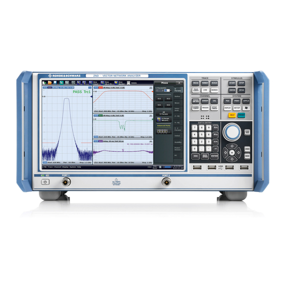
Allice Messtechnik GmbH ® Getting started R&S Instrument tour Printer configuration Use the "Printer Setup" dialog of the firmware (SYSTEM – [PRINT] > "Print...") or the ® Windows printer management to configure the printer properties and printing prefer- ences. - Page 34 Allice Messtechnik GmbH ® Getting started R&S Instrument tour Figure 3-1: Front View of R&S ZND 3.2.1.1 Touchscreen The analyzer is equipped with a 12.1'' XGA color touchscreen. The touchscreen pres- ents all measurement results, mostly in the form of diagrams. Besides, all instrument functions can be accessed and operated by tapping the control elements on the touch- screen.
- Page 35 Allice Messtechnik GmbH ® Getting started R&S Instrument tour Screen saver The screen saver function of the operating system can be used to switch off the display if the analyzer receives no command for a selectable period of time. The display is switched on again if any front panel key is pressed.
- Page 36 Allice Messtechnik GmbH ® Getting started R&S Instrument tour The SYSTEM keys provide general system settings. ● ® [FILE] provides standard Windows functions used to create, save, recall or print recall sets, to copy the active screen and to shut down the application.
- Page 37 Allice Messtechnik GmbH ® Getting started R&S Instrument tour – Confirm selections and entries made and close dialogs (equivalent to the "OK" button). – Compress or expand menus or the Help table of contents ● BACKSPACE deletes the last character before the cursor position or the selected character sequence or numeric value.
- Page 38 Allice Messtechnik GmbH ® Getting started R&S Instrument tour The standby toggle switch is located in the bottom-left corner of the front panel. The key serves two main purposes: ● Toggle between standby and ready state; see Chapter 3.1.8, "Standby and ready state",...
-
Page 39: Rear Panel
Allice Messtechnik GmbH ® Getting started R&S Instrument tour 3.2.2 Rear panel This section gives an overview of the rear panel controls and connectors of the net- work analyzer. Figure 3-2: Rear Panel R&S ZND The following connectors are available on all instruments: ●... -
Page 40: Operating The Instrument
Allice Messtechnik GmbH ® Getting started R&S Operating the instrument ● The ground connector in the lower left corner of the rear panel provides the ground of the analyzer's supply voltage. Use this connector for ESD protection; see "Pre- venting electrostatic discharge (ESD)"... - Page 41 Allice Messtechnik GmbH ® Getting started R&S Operating the instrument Figure 3-3: Function Keys Customizing the screen The contents of the screen and the size and position of many display and control ele- ments are not fixed. You can display or hide most elements. You can also drag and drop traces, info fields, and even the softtool panel to your preferred position;...
- Page 42 Allice Messtechnik GmbH ® Getting started R&S Operating the instrument left = unidirectional R&S ZND right = bidirectional R&S ZND 2. Activate the desired softtool tab, e.g. "Z←Sij". left = unidirectional R&S ZND right = bidirectional R&S ZND 3. Select a control element, e.g. "Z←S11".
- Page 43 Allice Messtechnik GmbH ® Getting started R&S Operating the instrument Using the menu bar The menu bar at the bottom of the application screen provides alternative access to all instrument functions. To repeat the measured quantity selection described above, ►...
- Page 44 Allice Messtechnik GmbH ® Getting started R&S Operating the instrument left = unidirectional R&S ZND right = bidirectional R&S ZND 2. Select "S-Parameter" to open the "Meas" > "S-Params" softtool tab. left = unidirectional R&S ZND right = bidirectional R&S ZND 3.
-
Page 45: Control Elements Of The Application Window
Allice Messtechnik GmbH ® Getting started R&S Operating the instrument left = unidirectional R&S ZND right = bidirectional R&S ZND 3.3.2 Control elements of the application window The application window of the analyzer provides all control elements for the measure- ments and contains the diagrams for the results. - Page 46 Allice Messtechnik GmbH ® Getting started R&S Operating the instrument These methods are described in more detail in the following sections. For further reference: ● Refer to Chapter 4.2.1, "Display elements of a diagram", on page 86 to obtain information about the results in the diagram.
- Page 47 Allice Messtechnik GmbH ® Getting started R&S Operating the instrument The toolbar is divided into several icon groups, separated by vertical lines. These icons represent the undo and redo actions that are also available via the menu bar items "System" > "Undo" / "Redo".
- Page 48 Allice Messtechnik GmbH ® Getting started R&S Operating the instrument Figure 3-4: Scale softtool A softtool consists of a title area with a close/re-open icon and a tabbed panel below it. The title area remains displayed when the softtool is closed, which allows you to reopen a closed softtool at any time.
- Page 49 Allice Messtechnik GmbH ® Getting started R&S Operating the instrument ● The "Display" menu provides all display settings and the functions for activating, modifying and arranging different diagrams. ● The "Application" menu gives access to applications and tools that extend the func- tionality of the analyzer firmware.
- Page 50 Allice Messtechnik GmbH ® Getting started R&S Operating the instrument 3.3.2.6 Hardkey panel The (virtual) "Hard Key" panel provides on-screen access to the function keys (plus the [UNDO] and [REDO] key) of the R&S ZND. Most of the function keys open a related softtool.
-
Page 51: Working With Dialogs
Allice Messtechnik GmbH ® Getting started R&S Operating the instrument ● the "EXT REF" symbol, if an external reference clock is used for synchronization (see "Ext Frequency" on page 565) ● the switch matrix status symbol, if a switch matrix is configured (See Chapter 4.7.20, "External switch... -
Page 52: Handling Diagrams, Traces, And Markers
Allice Messtechnik GmbH ® Getting started R&S Operating the instrument – Use the "Dialog Transparency" function to make the display elements behind the dialog visible. Note: The "Dialog Transparency" is a global setting, i.e. it applies to all dialogs. - Page 53 Allice Messtechnik GmbH ® Getting started R&S Operating the instrument 2. Select the adequate drop position, depending on whether you want to display the new trace in the existing diagram, or whether you want to add a new diagram. The highlighted area indicates the target diagram.
- Page 54 Allice Messtechnik GmbH ® Getting started R&S Operating the instrument Alternative control elements To measure a different quantity, select TRACE – [MEAS]. Drag and drop a softkey rep- resenting a measured quantity to create a trace. Or simply select another softkey to change the measured quantity of the active trace.
- Page 55 Allice Messtechnik GmbH ® Getting started R&S Operating the instrument 3.3.4.3 Deleting display elements Markers, traces, diagrams, and other display elements are most conveniently deleted using the "Delete" icon in the toolbar above the diagram area. ● To delete a single marker, drag it into vertical direction to release it from the trace and drop it onto the "Delete"...
-
Page 56: Entering Data
Allice Messtechnik GmbH ® Getting started R&S Operating the instrument Screen element Action Drag and drop... Reset / suspend "Zoom" element in additional trace line --> "Delete" icon; see Chapter 3.3.6.1, graphic zoom "Using the graphical zoom", on page 59... - Page 57 Allice Messtechnik GmbH ® Getting started R&S Operating the instrument ● Use [-] to change the sign of the value. ● (-)9 Use [G/n], [M/μ], [k/m], or [x1] to multiply the entered value with factors of 10 (-)6 , 10 (-)3 or 1 and to add the appropriate physical unit.
- Page 58 Allice Messtechnik GmbH ® Getting started R&S Operating the instrument 3. If desired, select a "Step Size" and use the cursor up/down buttons to increment/ decrement the current value. If a marker is active, you can also set the numeric value to the current marker value ("Set to Marker").
-
Page 59: Scaling Diagrams
Allice Messtechnik GmbH ® Getting started R&S Operating the instrument Figure 3-6: Windows 10 on-screen keyboard To call up the on-screen keyboard: 1. Open the SYSTEM – [APPLIC] softtool. 2. In the "External Tools" tab, select "Screen Keyboard". 3.3.6 Scaling diagrams The analyzer provides various tools for customizing the diagrams and for setting the sweep range. - Page 60 Allice Messtechnik GmbH ® Getting started R&S Operating the instrument The icon changes its background color from black to blue. ● In the active diagram area, select an appropriate rectangular area. The zoomed view shows the selected rectangle, scaled in both horizontal and verti- cal direction.
- Page 61 Allice Messtechnik GmbH ® Getting started R&S Operating the instrument Alternative settings ● The TRACE – [SCALE] > "Zoom" softtool tab allows you to define the displayed zoom range numerically. It can also be opened from the menu of the "Zoom Config" toolbar icon.
- Page 62 Allice Messtechnik GmbH ® Getting started R&S Operating the instrument ● Tap and hold (with a mouse: right-click) the "Start" or "Stop" label in the channel list and select "Start Frequency", "Stop Frequency", "Center Frequency", or "Fre- quency Span" from the context menu.
- Page 63 Allice Messtechnik GmbH ® Getting started R&S Operating the instrument 3.3.6.5 Circular diagrams The radial scale of a circular diagram ("Polar", "Smith" or "Inverted Smith") can be changed with a single linear parameter, the "Ref Value". The reference value defines the radius of the outer circumference.
- Page 64 Allice Messtechnik GmbH ® Getting started R&S Operating the instrument 2. Place "M1" to the start value of the desired sweep range and tap TRACE – [MARKER] > "Set by Marker" > "Start = Marker". 3. Place "M2" to the stop value of the desired sweep range and tap TRACE –...
-
Page 65: Performing Measurements
Allice Messtechnik GmbH ® Getting started R&S Performing measurements 3.4 Performing measurements This chapter takes you through a sample session with a R&S ZND network analyzer and describes basic operation tasks. Prerequisite The instrument is set up, connected to the mains system, and started up as described Chapter 3.1, "Preparing for... - Page 66 Allice Messtechnik GmbH ® Getting started R&S Performing measurements 1. Connect the DUT between test ports 1 and 2 of the network analyzer as shown above. 2. Use the [PRESET] key to restore a well-defined instrument state. The analyzer is now set to its default state. The default measured quantity is the transmission S-parameter S Select TRACE –...
- Page 67 Allice Messtechnik GmbH ® Getting started R&S Performing measurements 2. The stimulus signal from the analyzer port no. 2 is not needed except for some cali- bration types. By default the sweep range is set to the frequency range of the analyzer, which can be unsuitable for your DUT.
- Page 68 Allice Messtechnik GmbH ® Getting started R&S Performing measurements Due to the R&S ZND's calibration wizard, calibration is a straightforward, guided proc- ess. 1. Replace the DUT by the Through standard of your calibration kit. Make sure to dis- connect all calibration units.
- Page 69 Allice Messtechnik GmbH ® Getting started R&S Performing measurements 6. Tap"Start". 7. The calibration dock widget indicates the standard measurements that make up a "Trans Norm" calibration. Select "Through (mm)" to initiate the measurement of the connected Through stan- dard.
- Page 70 Allice Messtechnik GmbH ® Getting started R&S Performing measurements The analyzer performs a calibration sweep for the measured quantity S . The magnitude and phase of the result is displayed in two diagrams, together with the expected typical result for a Through standard. The similarity of real and expected traces indicates that the Through standard has been properly connected.
- Page 71 Allice Messtechnik GmbH ® Getting started R&S Performing measurements The group delay represents the propagation time of the wave through the DUT; it is displayed in a Cartesian diagram. The marker info field shows the frequency and group delay at the marker position.
-
Page 72: Reflection S-Parameter Measurement
Allice Messtechnik GmbH ® Getting started R&S Performing measurements 7. In the "Save" dialog: a) Select a file location ("Look in:"). b) Enter a name for the recall set file ("File name:"). c) Select "Save". The analyzer saves the active recall set, containing channel, stimulus and trace settings, to a znx file. - Page 73 Allice Messtechnik GmbH ® Getting started R&S Performing measurements ● Some of the trace formats are particularly suited for reflection measurements. For instance, you can display the measured reflection coefficient S in a Smith chart to obtain the complex input impedance at port 1.
-
Page 74: Concepts And Features
Allice Messtechnik GmbH ® Concepts and features R&S Basic concepts 4 Concepts and features The following chapter provides an overview of the analyzer's capabilities and their use. It contains a description of the basic concepts that the analyzer uses to organize, proc- ess and display measurement data. -
Page 75: Recall Sets
Allice Messtechnik GmbH ® Concepts and features R&S Basic concepts ● Cal pool data including system error correction and power correction data ● Directories for trace data, limit lines, calibration data etc. ● Color schemes and printer settings ●... - Page 76 Allice Messtechnik GmbH ® Concepts and features R&S Basic concepts 4.1.3.1 Trace settings The trace settings specify the mathematical operations used to obtain traces from the measured or stored data. They can be divided into several main groups: ●...
-
Page 77: Sweep Control
Allice Messtechnik GmbH ® Concepts and features R&S Basic concepts 4.1.3.3 Active and inactive traces and channels A window can display several diagrams simultaneously, each with a variable number of traces. One of these traces is active at each time. The active trace is highlighted in the trace list on top of the active diagram (Trc4 in the figure below): When a trace is selected in the diagram area, it becomes the active trace. - Page 78 Allice Messtechnik GmbH ® Concepts and features R&S Basic concepts After changing the channel settings or selecting another measured quantity, the ana- lyzer needs some time to initialize the new sweep. This preparation period increases with the number of points and the number of partial measurements involved. It indica- ted in the status bar: All analyzer settings can still be changed during sweep initialization.
- Page 79 Allice Messtechnik GmbH ® Concepts and features R&S Basic concepts Use the "Alternated" mode to increase the accuracy of measurements on DUTs with long level settling times (e.g. quartzes, SAW filters). To measure DUTs with short set- tling times and obtain a trace from the beginning of the sweep, use "Chopped" mode.
- Page 80 Allice Messtechnik GmbH ® Concepts and features R&S Basic concepts Ch1 Sweep End Ch2 Sweep End Ch3 Sweep End Ch1 HW Sweep Ch2 HW Sweep Ch3 HW Sweep … Ch1 Calc Ch2 Calc Ch3 Calc Ch1 Results Ch2 Results...
- Page 81 Allice Messtechnik GmbH ® Concepts and features R&S Basic concepts With unidirectional operation, the following restrictions apply: ● S12, S22 and wave quantities of the reverse direction (port 2 as source) are not available ● Other (derived) results that require driving both ports, such as Y- and Z-parameters or stability parameters, are not available ●...
-
Page 82: Data Flow
Allice Messtechnik GmbH ® Concepts and features R&S Basic concepts – For "Segmented" sweeps, the start and stop frequency in a sweep segment must not be different. So with a segmented sweep you can measure n points at frequency f... - Page 83 Allice Messtechnik GmbH ® Concepts and features R&S Basic concepts RAW WAVE Channel data flow QUANTITIES for all traces of the channel SYSTEM ERROR CORRECTION (Factory) SYSTEM POWER POWER SYST. ERR. ERROR CORRECTION CORRECTION CORRECTION CORRECTION DATA (User) DATA...
- Page 84 Allice Messtechnik GmbH ® Concepts and features R&S Basic concepts calibration on the measured wave quantities, intermediate results were transformed to the S-parameter domain. Before each de-/embedding step, the S-parameters were transformed to conductance (~ wave quantities), and vice versa afterwards.
- Page 85 Allice Messtechnik GmbH ® Concepts and features R&S Basic concepts Channel data flow for all traces AVERAGE of the channel Trace 1 Mem 1,1 Mem 1,2 Trace 2 Mem 2,1 Mem 2,2 Unformatted Trace data flow TRACE MATH for individual traces...
-
Page 86: Screen Elements
Allice Messtechnik GmbH ® Concepts and features R&S Screen elements 4.2 Screen elements This section describes manual operation of the analyzer, including trace settings, mark- ers and diagrams. For a description of the different quantities measured by the instru- ment, refer to Chapter 4.3, "Measurement... - Page 87 Allice Messtechnik GmbH ® Concepts and features R&S Screen elements 4.2.1.1 Title An optional title across the top of the diagram can be used for a brief description of the diagram contents. Select SYSTEM – [DISPLAY] > "Diagram" > "Title" to enter the diagram title and "Show Title"...
- Page 88 Allice Messtechnik GmbH ® Concepts and features R&S Screen elements The type of each trace in a diagram is indicated in the trace list: "MEM<no>" at the beginning of the trace name indicates a memory trace (with default naming), Math at the end of the trace label indicates a mathematical trace.
- Page 89 Allice Messtechnik GmbH ® Concepts and features R&S Screen elements Example: The following context menu is assigned to the measured quantity section in the trace list: A label "Cal Off" appears at the end of the trace line if the system error correction no longer applies to the trace.
- Page 90 Allice Messtechnik GmbH ® Concepts and features R&S Screen elements The most common tasks to be performed with markers can be achieved using the "Marker" menu functions: ● Determine the coordinates of a measurement point on the trace. In polar diagrams where no x-axis is displayed, markers can be used to retrieve the stimulus value of specific points.
- Page 91 Allice Messtechnik GmbH ® Concepts and features R&S Screen elements markers assigned to a trace are independent of each other and of the trace format settings. ● The active marker has a dot placed in front of the marker line.
- Page 92 Allice Messtechnik GmbH ® Concepts and features R&S Screen elements trace (the raw measurement data) and the respective target format. This must be kept in mind when interpreting the results and physical units displayed. The following table describes how a complex marker value z = x + jy is converted. It jφ(z)
- Page 93 Allice Messtechnik GmbH ® Concepts and features R&S Screen elements Marker Format Description Formula Imp Mag Magnitude of (series) impedance | = (R IMP Mag series***) Imp Mag paral- Magnitude of parallel impedance | = (R lel***) Adm Mag...
- Page 94 Allice Messtechnik GmbH ® Concepts and features R&S Screen elements Only one kind of marker coupling can be enabled. For instance it is not possible to cou- ple markers per channel and per diagram at the same time. Basic marker search functions The search functions are tools for searching measurement data according to specific criteria.
- Page 95 Allice Messtechnik GmbH ® Concepts and features R&S Screen elements The info field contains the following search results: ● "Bandwidth" is the n-dB bandwidth of the bandpass/bandstop region, where n is a selectable bandwidth factor. The bandwidth is equal to the difference between the lower and the upper band edge frequency.
- Page 96 Allice Messtechnik GmbH ® Concepts and features R&S Screen elements Each line in the channel list describes a single channel. The channel of the active trace is highlighted. The lines are divided into several sections with the following contents (from left to right): ●...
-
Page 97: Dialogs
Allice Messtechnik GmbH ® Concepts and features R&S Screen elements ● Channel list (separate context menus for channel name section, sweep range sec- tion, additional parameter section) To open a context menu associated with a display element, tap and hold the element for some seconds. - Page 98 Allice Messtechnik GmbH ® Concepts and features R&S Screen elements numeric value is incremented or decremented, or when display elements are added or removed. In most dialogs, however, it is possible to cancel an erroneous input before it takes effect.
- Page 99 Allice Messtechnik GmbH ® Concepts and features R&S Screen elements ● "Windows Explorer" opens the selected directory in the Windows Explorer. ● "File name" specifies a filename to save the current data. The analyzer adds the extension in the "Files of type" field.
-
Page 100: Trace Formats
Allice Messtechnik GmbH ® Concepts and features R&S Screen elements Figure 4-4: Multi-channel setup dialog The channel selector in the title bar and the channel-related buttons in the lower part of the dialog ("Copy to New Channel", "Copy to New Ch + Diagram" allow you to select the target channels. - Page 101 Allice Messtechnik GmbH ® Concepts and features R&S Screen elements ● The x-axis scaling depends on the sweep type of the channel to which the trace is assigned: – For sweep types "Lin Freq", "Power", "CW Mode" and "Time" it is scaled line- arly.
- Page 102 Allice Messtechnik GmbH ® Concepts and features R&S Screen elements An extended range of formats and conversion formulas is available for markers. To convert any point on a trace, create a marker and select the appropriate marker format. Marker and trace formats can be selected independently.
- Page 103 Allice Messtechnik GmbH ® Concepts and features R&S Screen elements Example: Reflection coefficients in polar diagrams If the measured quantity is a complex reflection coefficient (S etc.), then the cen- ter of the polar diagram corresponds to a perfect load Z at the input test port of the DUT (no reflection, matched input).
- Page 104 Allice Messtechnik GmbH ® Concepts and features R&S Screen elements ● Points with the same reactance produce arcs. The following example shows a Smith chart with a marker used to display the stimulus value, the complex impedance Z = R + j X and the equivalent inductance L.
- Page 105 Allice Messtechnik GmbH ® Concepts and features R&S Screen elements dinates in the normalized impedance plane and in the reflection coefficient plane are related as follows (see also: definition of matched-circuit (converted) impedances): From this equation, it is easy to relate the real and imaginary components of the com- plex resistance to the real and imaginary parts of Γ:...
- Page 106 Allice Messtechnik GmbH ® Concepts and features R&S Screen elements In a diagram, the grid lines overlaid to a "Smith" trace correspond to points of equal conductance G and susceptance B: ● Points with the same conductance are located on circles.
- Page 107 Allice Messtechnik GmbH ® Concepts and features R&S Screen elements ● The upper and lower half of the diagram correspond to negative (inductive) and positive (capacitive) susceptive components of the admittance, respectively. Example: Reflection coefficients in the inverted Smith chart If the measured quantity is a complex reflection coefficient Γ...
-
Page 108: Measurement Results
Allice Messtechnik GmbH ® Concepts and features R&S Measurement results 4.2.3.3 Measured quantities and trace formats The analyzer allows any combination of a display format and a measured quantity. The following rules can help to avoid inappropriate formats and find the format that is ide- ally suited to the measurement task. -
Page 109: S-Parameters
Allice Messtechnik GmbH ® Concepts and features R&S Measurement results 4.3.1 S-parameters S-parameters are the basic measured quantities of a network analyzer. They describe how the DUT modifies a signal that is transmitted or reflected in forward or reverse direction. -
Page 110: Reference Impedances
Allice Messtechnik GmbH ® Concepts and features R&S Measurement results Meaning of squared amplitudes The squared amplitudes of the incident and outgoing waves and of the matrix elements have a simple meaning: Table 4-3: Squared S-parameters Available incident power (= the power provided by a generator with... - Page 111 Allice Messtechnik GmbH ® Concepts and features R&S Measurement results The default values for the balanced port reference impedances are derived from the default reference impedance of the physical analyzer ports (Z = 50 Ω): ● The default value for the differential mode is Z = 100 Ω...
-
Page 112: Impedance Parameters
Allice Messtechnik GmbH ® Concepts and features R&S Measurement results ... - Page 113 Allice Messtechnik GmbH ® Concepts and features R&S Measurement results Example: For a 2-port DUT that is terminated at its output with the reference impedance Z is the input impedance (matched-circuit impedance measured in a forward reflection measurement). A converted impedance Z completely describes a one-port DUT.
- Page 114 Allice Messtechnik GmbH ® Concepts and features R&S Measurement results Table 4-5: Calculation of Converted Series Transmission Impedances Traveling Waves Power Waves Parallel transmission impedance A two-port transmission parameter Z (i ≠ j) can also describe a parallel impedance between the two ports.
- Page 115 Allice Messtechnik GmbH ® Concepts and features R&S Measurement results 4.3.3.2 Z-parameters The Z-parameters describe the impedances of a DUT with open output ports (impe- dance = 0). The analyzer provides the full set of Z-parameters including the transfer impedances (i.e.
-
Page 116: Admittance Parameters
Allice Messtechnik GmbH ® Concepts and features R&S Measurement results ● is the output impedance, defined as the ratio of the voltage V to the current I measured at port 2 (reverse measurement with open input, I = 0). -
Page 117: Wave Quantities And Ratios
Allice Messtechnik GmbH ® Concepts and features R&S Measurement results ● is the forward transfer admittance, defined as the ratio of the current I to the voltage V (forward measurement with output terminated in a short circuit, V = 0). - Page 118 Allice Messtechnik GmbH ® Concepts and features R&S Measurement results Examples for using wave quantities The wave quantities provide the power at the different receive ports of the analyzer. This is different from an S-parameter measurement, where the absolute power of a lin- ear device is canceled.
- Page 119 Allice Messtechnik GmbH ® Concepts and features R&S Measurement results Examples for using ratios A measurement of ratios is particularly suitable for the following test scenarios: ● The test setup or some of its components (e.g. active components or non-recipro- cal devices) do not allow a system error correction so that a complete S-parameter measurement is not possible.
-
Page 120: Unbalance-Balance Conversion
Allice Messtechnik GmbH ® Concepts and features R&S Measurement results The following detectors are available: ● "Normal" selects the default detector mode where each valid measurement point is displayed without modification. The analyzer then proceeds to the next sweep point. - Page 121 Allice Messtechnik GmbH ® Concepts and features R&S Measurement results Internal balance- unbalance conversion Logical Physical VNA ports VNA ports Common Differential mode mode Balanced port Physical transformer (balun) Unbalance-balance conversion avoids the disadvantages of real transformers: ● There is no need to fabricate test fixtures with integrated baluns for each type of DUT.
- Page 122 Allice Messtechnik GmbH ® Concepts and features R&S Measurement results Example: 2 physical ports: Reflection measurements on 1 balanced port Balanced port: Differential mode Log. Bal. port port Common mode 3 physical ports: Reflection and transmission measurements on 1 balanced port...
- Page 123 Allice Messtechnik GmbH ® Concepts and features R&S Measurement results Mixed mode parameters are used to distinguish the following three port modes: ● s: Single-ended (for unbalanced ports) ● d: Differential mode (for balanced ports) ● c: Common mode (for balanced ports) The notation of a general S-parameter is S , where <mout>...
- Page 124 Allice Messtechnik GmbH ® Concepts and features R&S Measurement results 2. DUT with one balanced port: Only reflection and mode conversion measurements with differential and common mode parameters. 3. DUT with one balanced and one single-ended port. 4. DUT with two balanced ports or one balanced and two single-ended ports. Both device types are fully characterized by 4x4 mixed mode S-matrices.
-
Page 125: Stability Factors
Allice Messtechnik GmbH ® Concepts and features R&S Measurement results General Definition In general, imbalance and CMRR are quantities with two numeric indices, indicating the logical output port and the logical input port of the DUT during the measurement... -
Page 126: Delay, Aperture, Electrical Length
Allice Messtechnik GmbH ® Concepts and features R&S Measurement results where denotes the complex conjugate of S. Stability factors are calculated as functions of the frequency or another stimulus parameter. -
Page 127: Operations On Traces
Allice Messtechnik GmbH ® Concepts and features R&S Operations on traces In practice, the analyzer calculates an approximation to the derivative of the phase response, taking a small frequency interval Δf and determining the corresponding phase change ΔΦ. The delay is thus computed as: ... - Page 128 Allice Messtechnik GmbH ® Concepts and features R&S Operations on traces A limit check consists of comparing the measurement results to the limit lines and dis- play a pass/fail indication. An acoustic warning and a TTL signal at the USER PORT on the rear panel (for test automation) can be generated in addition if a limit is violated.
- Page 129 Allice Messtechnik GmbH ® Concepts and features R&S Operations on traces When the sweep axis is changed from linear frequency sweep to logarithmic sweeps, straight limit lines are transformed into exponential curves. The sweep points are redis- tributed along the x-axis, so the number of failed points can change.
- Page 130 Allice Messtechnik GmbH ® Concepts and features R&S Operations on traces 4.4.1.2 Rules for ripple test definition The analyzer places few restrictions on the definition of ripple limit ranges. The following rules ensure a maximum of flexibility: ● Ranges do not have to be sorted in ascending or descending order (e.g. the "Start Stimulus"...
- Page 131 Allice Messtechnik GmbH ® Concepts and features R&S Operations on traces The limit line rules for logarithmic sweeps and segmented frequency sweeps with point-based x-axis also apply to ripple limit lines (see Chapter 4.4.1.1, "Rules for limit line definition", on page 128).
- Page 132 Allice Messtechnik GmbH ® Concepts and features R&S Operations on traces ● With a circle limit line centered on the left border of an inverted Smith diagram (Y = infinity), you can check whether the imaginary part of the admittance (Im(Y), sus- ceptance) falls below a limit.
- Page 133 Allice Messtechnik GmbH ® Concepts and features R&S Operations on traces 4.4.1.4 File format for limit lines The analyzer uses a simple ASCII format to export limit line data. By default, the limit line file has the extension *.limit and is stored in the directory shown in the "Save Limit Line"...
-
Page 134: Trace Files
Allice Messtechnik GmbH ® Concepts and features R&S Operations on traces Compatibility with other instruments The VNAs of the R&S ZNx and R&S ZVx families use the same file format. Limit line files can be interchanged without restriction. 4.4.1.5 File format for ripple limits The analyzer uses a simple ASCII format to export ripple limits. - Page 135 Allice Messtechnik GmbH ® Concepts and features R&S Operations on traces ● When exporting traces to a file, it is recommended to set the analyzer to single sweep mode (CHANNEL – [SWEEP] > "Sweep Control" > "All Channels on Hold").
- Page 136 Allice Messtechnik GmbH ® Concepts and features R&S Operations on traces # <frequency unit> <parameter> <data format> R <reference resistance> ● # indicates the beginning of the option line ● <frequency unit> can be either Hz, kHz, MHz or GHz. Default is GHz.
- Page 137 Allice Messtechnik GmbH ® Concepts and features R&S Operations on traces Timestamp The timestamp comment line reflects the time at which the Touchstone file was cre- ated. For "Version 1.1 (ZNx)" export format, it is represented as Coordinated Universal...
- Page 138 Allice Messtechnik GmbH ® Concepts and features R&S Operations on traces ● "Version 1.1" and "Version 2.0" export formats These export formats always use single-ended identifiers Sij and port numbers 1 to n in the table header. ! freq[Hz] S11[Re] S11[Im] ...
- Page 139 Allice Messtechnik GmbH ® Concepts and features R&S Operations on traces The purpose of the keywords is to give more details about the file contents in a stand- ardized way. During "Version 2.0" export, the R&S ZND writes the following keywords...
- Page 140 Allice Messtechnik GmbH ® Concepts and features R&S Operations on traces first (or only) data line of a data block is a frequency value. The complex network parameter data is formatted as pairs of values. The following general rules apply ●...
- Page 141 Allice Messtechnik GmbH ® Concepts and features R&S Operations on traces 1.000000000000000e+09 -2.375070438098596e-01 -4.533104459856211e-01 1.010000000000000e+09 -3.132740349817996e-01 -5.874596585157938e-01 1.020000000000000e+09 -3.062444919836442e-01 -4.587379501906624e-01 Conditions for Touchstone file export ● One-port Touchstone files with data from a single trace Typically, Touchstone files contain a complete set of S-parameter traces of an n- port network.
- Page 142 Allice Messtechnik GmbH ® Concepts and features R&S Operations on traces In this case, the reference impedances of the individual ports are used for the renormalization and these impedances are documented in the Renormalization information comment. If the port-specific reference impedances are different, an additional warning is added to this comment, indicating that the option line contains a non-matching reference resistance.
-
Page 143: Memory-Mapped Trace Data Transfer
Allice Messtechnik GmbH ® Concepts and features R&S Operations on traces The stimulus values are arranged in ascending order. 4.4.2.3 Finding the best file format The file format depends on how you want to use the exported data. Use a Touchstone file format to export S-parameter data traces to a file that can be... - Page 144 Allice Messtechnik GmbH ® Concepts and features R&S Operations on traces Set up a shared memory buffer The setup of a shared memory buffer and the allocation of trace data is performed by a sequence of SYSTem:DATA:MEMory... commands, starting with an INITialize and finished by a COMMit.
-
Page 145: Calibration
Allice Messtechnik GmbH ® Concepts and features R&S Calibration 4.5 Calibration Calibration or system error correction is the process of eliminating systematic, reprodu- cible errors from the measurement results (S-parameters and derived quantities; see Chapter 4.1.5, "Data flow", on page 82). The process involves the following stages: 1. -
Page 146: Calibration Types
Allice Messtechnik GmbH ® Concepts and features R&S Calibration Cal Off label A label "Cal Off" appears in the trace line if the system error correction no longer applies to the trace: This can happen for one of the following reasons: ●... - Page 147 Allice Messtechnik GmbH ® Concepts and features R&S Calibration Calibration Type Standards Parameters Error Terms General Accuracy Application One Path Two Ports Open, Short, for fixed source Reflection tracking, Medium to high Unidirectional trans- mission measure- Match (at source...
- Page 148 Allice Messtechnik GmbH ® Concepts and features R&S Calibration Calibration Type Standards Parameters Error Terms General Accuracy Application Through, Attenua- Reflection tracking, High, lowest Reflection and tion, Symmetric requirements on transmission mea- (2-port) Source match, network standards surements, espe-...
-
Page 149: Reflection Osm Calibration
Allice Messtechnik GmbH ® Concepts and features R&S Calibration ● Manual reflection normalizations offer Complementary Match standard measure- ments ● Manual transmission normalizations support Complementary isolation measure- ment (optional). Complementary Match standard measurements For reflection normalizations, the mandatory Open or Short measurements can be complemented by optional Match measurements. -
Page 150: Tosm And Uosm Calibration
Allice Messtechnik GmbH ® Concepts and features R&S Calibration With a unidirectional R&S ZND (see Chapter 4.1.4.3, "R&S ZND: unidirectional vs. bidirectional operation", on page 80) only the forward direction (source port 1) is availa- ble. 4.5.1.4 TOSM and UOSM calibration TOSM A TOSM (Through –... -
Page 151: Adapter Removal
Allice Messtechnik GmbH ® Concepts and features R&S Calibration After acquiring the calibration sweep data for the unknown through, the analyzer auto- matically determines its delay time/transmission phase. 4.5.1.5 Adapter removal Many DUTs use different connector types on their RF ports (e.g. port 1: N-type connec- tor, female;... -
Page 152: Tom Calibration
Allice Messtechnik GmbH ® Concepts and features R&S Calibration Figure 4-7: Adapter Removal vs. UOSM The obtained adapter characteristics are mathematically removed from the obtained error coefficients. Uncertainties arising from a non-ideal characterization of the unknown through almost cancel, whereas they add up in the UOSM technique. As a consequence, Adapter Removal will provide more accurate results. -
Page 153: Trm Calibration
Allice Messtechnik GmbH ® Concepts and features R&S Calibration 4.5.1.8 TRM calibration A TRM (Through – Reflect – Match) calibration requires a low-reflection, low-loss Through standard with an electrical length that can be different from zero, a Reflect, and a Match. The magnitude of the reflection coefficient of the Reflect standard can be unknown but must be nonzero;... - Page 154 Allice Messtechnik GmbH ® Concepts and features R&S Calibration To shift the calibrated sweep range to smaller or larger frequencies, you can use a lon- ger or shorter Line. To extend the calibrated range, use one of the following methods: ●...
-
Page 155: Tna Calibration
Allice Messtechnik GmbH ® Concepts and features R&S Calibration ● The shorter Line can be used from a frequency f where its transmission phase short is equal to 20 deg. This frequency is equal to /[18*(l – l short short ●... -
Page 156: Full N-Port Calibration With Reduced Number Of Through Connections
Allice Messtechnik GmbH ® Concepts and features R&S Calibration must be well matched on both sides and cause an attenuation different from 0 dB; the exact value of the transmission coefficient is not important. As with TRL, TNA calibration is especially useful for planar DUTs. If TNA is not practi- cable, TRL can be an alternative. -
Page 157: Calibration Standards And Calibration Kits
Allice Messtechnik GmbH ® Concepts and features R&S Calibration possible through connections are measured by default. If you want to apply the "Reduced Through" logic also for each port assignment, you can activate it in the system configuration. 4.5.1.12... - Page 158 Allice Messtechnik GmbH ® Concepts and features R&S Calibration 4.5.2.1 Calibration standard types The following table gives an overview of the different standards and their circuit models (offset and load models). Table 4-8: Calibration standard types Standard Type Characteristics...
- Page 159 Allice Messtechnik GmbH ® Concepts and features R&S Calibration ● The loss is the energy loss along the transmission line due to the skin effect. For resistive lines and at RF frequencies, the loss is approximately proportional to the square root of the frequency.
- Page 160 Allice Messtechnik GmbH ® Concepts and features R&S Calibration 4.5.2.2 Cal kit parameter types The analyzer uses three types of parameters to describe the calibration standards. The parameter type is the same for all standards in a kit and therefore appended to the kit name: ●...
- Page 161 Allice Messtechnik GmbH ® Concepts and features R&S Calibration The following additional parameters are used: ● Characteristic impedance: Z (characteristic impedance of the connector type) ● Loss: 0 dB / sqrt(GHz) or (0 GΩ / s) in Keysight mode ●...
- Page 162 Allice Messtechnik GmbH ® Concepts and features R&S Calibration ● The Sliding Match results are used for frequencies above the Min Freq. In general, the Sliding Match provides better results than the Match within its specified fre- quency range.
-
Page 163: Calibration Pool
Allice Messtechnik GmbH ® Concepts and features R&S Calibration The network analyzer expects the dot as a separator and displays an error message when a *.csv file with commas is loaded. Please install the VNA Cal Kit Manager ®... -
Page 164: Automatic Calibration
Allice Messtechnik GmbH ® Concepts and features R&S Calibration 4.5.5 Automatic calibration A calibration unit is an integrated solution for automatic system error correction of vec- tor network analyzers. Rohde & Schwarz offers a wide range of calibration units for dif- ferent frequency ranges and connector types. - Page 165 Allice Messtechnik GmbH ® Concepts and features R&S Calibration 4.5.5.1 Connecting the calibration unit The calibration units provide the following connectors: ● USB type B connector at the rear, which is used to power-supply and control the unit. A USB cable for connection to the network analyzer is provided with the cali- bration unit.
- Page 166 Allice Messtechnik GmbH ® Concepts and features R&S Calibration 4.5.5.2 Performing an automatic calibration After connection and initialization of the calibration unit, perform the automatic calibra- tion of the related test ports using the "Calibration Unit" wizard (CHANNEL – [CAL] >...
- Page 167 Allice Messtechnik GmbH ® Concepts and features R&S Calibration ● A one path two port calibration. The node port is the source port for the one path two port calibration (fully calibrated port). ● A transmission normalization (bidirectional, forward or reverse). "Forward" trans- mission normalization means that the signal direction is from port 1 to port 2.
- Page 168 Allice Messtechnik GmbH ® Concepts and features R&S Calibration 4.5.5.4 Inline calibration Any disturbance of the measurement setup after the calibration process inevitably pro- duces errors. If a massive system error correction is required, e.g. if long RF cables with high damping are used, those disturbances can lead to inaccurate and unreprodu- cible measurement results.
- Page 169 Allice Messtechnik GmbH ® Concepts and features R&S Calibration Figure 4-10: ICC R&S ZN-Z30 For more information, see the R&S ZN-Z3x product pages at https://www.rohde- schwarz.com/product/NetworkAnalyzer_Acc_ZNZ3. Firmware integration The control connection between R&S ZND and ICC is established via USB. After the VNA firmware has detected the ICC, it requests information about connected ICUs from the ICC.
- Page 170 Allice Messtechnik GmbH ® Concepts and features R&S Calibration Because the ICC does not support hot plugging of ICUs, connect the ICUs to the ICC before connecting the ICC to the R&S ZND. The VNA firmware supports: ● Pulling characterization data for the connected ICUs from the ICC ●...
- Page 171 Allice Messtechnik GmbH ® Concepts and features R&S Calibration Step 1: OSM g) Step 2: Unknown Through 5. Connect the DUT to the calibrated setup and perform the required measurements. 6. Refresh the calibration in situ, whenever required. a) "Repeat" the calibration b) Perform OSM measurements.
- Page 172 Allice Messtechnik GmbH ® Concepts and features R&S Calibration brated channel, only the two connected instrument ports are validated against the cal unit. The validation logic proceeds through the connected ports p ∈ {1, ..., 4} in ascending order, measuring S for the Open, Short and Match standard.
- Page 173 Allice Messtechnik GmbH ® Concepts and features R&S Calibration For a channel with more calibrated ports than cal unit ports available, you can change the port assignments and rerun the automated validation. Or you can switch to advanced mode and validate each port manually.
- Page 174 Allice Messtechnik GmbH ® Concepts and features R&S Calibration the calibration type, a "minimal" valid and complete solution can be described as fol- lows: Calibration Minimal solution Default solution (minimal) type Full One Port Each calibrated test port must appear in exactly one Subdivide the n test ports into port assignment.
-
Page 175: Scalar Power Calibration
Allice Messtechnik GmbH ® Concepts and features R&S Calibration Example: The following examples show minimal port assignments for a Full 9-Port calibration using a four-port calibration unit: Table 4-11: Full n-port: Star-shaped optimum solution Test Port Assignment 1 Assignment 2... - Page 176 Allice Messtechnik GmbH ® Concepts and features R&S Calibration Table 4-13: System error correction and power calibration for various measurements Measurement System error correction Scalar power calibration S-parameter meas. on linear Yes, necessary Not necessary DUTs Meas. of wave quantities or ratios...
- Page 177 Allice Messtechnik GmbH ® Concepts and features R&S Calibration calibration plane or to any other point in the test setup where the signal power is known to be proportional to the power at the calibration plane. By default, the source power calibration involves several steps: 1.
- Page 178 Allice Messtechnik GmbH ® Concepts and features R&S Calibration A measurement receiver calibration generally improves the accuracy of power (wave quantity) measurements. The correction data acquired in a frequency or power sweep is re-used if a "Time" or "CW Mode" sweep is activated.
- Page 179 Allice Messtechnik GmbH ® Concepts and features R&S Calibration Calibration of S-parameters S-parameters and derived quantities (e.g. impedances, admittances, stability factors) are assumed to be linear. Therefore, a scalar power calibration is not applied to S-parameters and derived quan- tities;...
- Page 180 Allice Messtechnik GmbH ® Concepts and features R&S Calibration manually or automatically (CHANNEL – [CAL] > "Pwr Cal Settings" > "Transm. Coeffi- cients..."). The R&S ZND supports two different test scenarios. A: Two-port at DUT (during measurement) Test and measurement procedure: 1.
-
Page 181: Parallel Calibration Of Multiple Channels
Allice Messtechnik GmbH ® Concepts and features R&S Calibration Practical example: An adapter or attenuator with known attenuation is needed to con- nect the power sensor to the test port of the network analyzer. The transmission coeffi- cients of the adapter are used for the power meter correction. -
Page 182: Offset Parameters And De-/Embedding
Allice Messtechnik GmbH ® Concepts and features R&S Offset parameters and de-/embedding 4.6 Offset parameters and de-/embedding The R&S ZND functionality described in this section complements the calibration, com- pensating for the effect of known transmission lines or matching networks between the calibrated reference plane and the DUT. - Page 183 Allice Messtechnik GmbH ® Concepts and features R&S Offset parameters and de-/embedding In the limit case, where the length of the transmission line is considered to be "almost zero", the loss is considered constant: Otherwise, if the loss at DC and one additional frequency f...
- Page 184 Allice Messtechnik GmbH ® Concepts and features R&S Offset parameters and de-/embedding This yields the delay for propagation in forward and reverse direction and should be approx. twice the "Auto Length" result. For transmission measurements, both results should be approx. equal.
- Page 185 Allice Messtechnik GmbH ® Concepts and features R&S Offset parameters and de-/embedding "Auto Length and Loss" involves a two-step procedure: ● An "Auto Length" correction modifies the phase of the measured quantity, minimiz- ing the residual group delay. The magnitude of the measured quantity is not affec- ted.
- Page 186 Allice Messtechnik GmbH ® Concepts and features R&S Offset parameters and de-/embedding 4.6.1.5 Fixture Compensation "Fixture Compensation" is an automated length offset and loss compensation for test fixtures. The analyzer performs a one-port reflection measurement at each port, assuming the inner contacts of the test fixtures to be terminated with an open or short circuit.
- Page 187 Allice Messtechnik GmbH ® Concepts and features R&S Offset parameters and de-/embedding fixture compensation sweeps to compensate for the inaccuracies of the individual "Open and Short" compensations. 4.6.1.6 Application and effect of offset parameters Offset and loss parameters can be particularly useful if the reference plane of the cali- bration cannot be placed directly at the DUT ports, e.g.
-
Page 188: Embedding And Deembedding
Allice Messtechnik GmbH ® Concepts and features R&S Offset parameters and de-/embedding ● "Auto Length" corrects the length offset of both physical ports of a logical port by the same amount. 4.6.2 Embedding and deembedding The R&S ZND allows you to define virtual networks to be added to/removed from the measurement circuit for a DUT with single ended or balanced ports. - Page 189 Allice Messtechnik GmbH ® Concepts and features R&S Offset parameters and de-/embedding Single-ended Balanced port port Balun Matching circuit The idea of virtual embedding is to simulate the matching network and avoid using physical circuitry so that the analyzer ports can be directly connected to the input and output ports of the DUT.
- Page 190 Allice Messtechnik GmbH ® Concepts and features R&S Offset parameters and de-/embedding To be numerically removed, the real network must be described by a set of S-parame- ters or by an equivalent circuit of lumped elements. Deembedding the DUT effectively extends the calibration plane towards the DUT ports, enabling a realistic evaluation of the DUT without the distorting network.
- Page 191 Allice Messtechnik GmbH ® Concepts and features R&S Offset parameters and de-/embedding The following networks are composed of a shunt C or L (as seen from the analyzer port), followed by a serial C or L. They are named Shunt C, Serial L / Shunt L, Serial C / Shunt C, Serial C / Shunt L, Serial L.
- Page 192 Allice Messtechnik GmbH ® Concepts and features R&S Offset parameters and de-/embedding parameters, or the entire transformation network can be described by imported 4-port S-parameters. The first network is defined by its S-parameters stored in an imported four-port Touch- stone file (*.s4p).
- Page 193 Allice Messtechnik GmbH ® Concepts and features R&S Offset parameters and de-/embedding Since FW version 1.93, the "capacitance C<i> in parallel with resistance R<i>" circuit blocks can alternatively be represented as "capacitance C<i> in parallel with conduc- tance G<i>" circuit blocks.
- Page 194 Allice Messtechnik GmbH ® Concepts and features R&S Offset parameters and de-/embedding Network Analyzer Embedding Network 2m-1 Figure 4-11: Port Set De-/Embedding As shown in section Combining Several de-/embedding networks, port set deembed- ding is calculated after single-ended deembedding, and the port set embedding step precedes single ended embedding.
- Page 195 Allice Messtechnik GmbH ® Concepts and features R&S Offset parameters and de-/embedding ● For the R&S ZND, each port set can consist of m = 2 ports ● For these port pairs, the de-/embedding network can be defined either via lumped...
- Page 196 Allice Messtechnik GmbH ® Concepts and features R&S Offset parameters and de-/embedding Differential Matching Network Balun In contrast to standard balanced embedding (4-port), the matching circuit is only applied to the differential mode port (2-port). It can be specified via a Touchstone s2p file or by parametrizing a lumped "Shunt L, Shunt C"...
- Page 197 Allice Messtechnik GmbH ® Concepts and features R&S Offset parameters and de-/embedding Fixture Modeling Process For all supported tools, the fixture modeling proceeds as follows: 1. Perform a calibration to the fixture connectors. 2. Measure one or more PCB test coupons for the related fixture.
- Page 198 Allice Messtechnik GmbH ® Concepts and features R&S Offset parameters and de-/embedding Test Coupons for Lead-ins Test Coupons for Lead-outs 2x Through 2x Through 1x Open 1x Short 1x Open 1x Short Figure 4-13: Test Coupons (balanced) Test Coupons for Lead-ins...
- Page 199 Allice Messtechnik GmbH ® Concepts and features R&S Offset parameters and de-/embedding Figure 4-15: De-/Embedding calculation flow This means that the real networks are removed before virtual networks are added. The (de-)embedding steps are carried out in the following order: 1.
-
Page 200: Optional Extensions And Accessories
Allice Messtechnik GmbH ® Concepts and features R&S Optional extensions and accessories 3. Balanced port deembedding 4. Balanced port embedding 5. Single ended port embedding 4.7 Optional extensions and accessories The instrument can be upgraded with various software and hardware options, provid- ing enhanced flexibility and an extended measurement functionality. -
Page 201: Frequency Range Extension To 8.5 Ghz For Unidirectional R&S Znd
Allice Messtechnik GmbH ® Concepts and features R&S Optional extensions and accessories 4.7.1 Frequency range extension to 8.5 GHz for unidirectional R&S ZND Option R&S ZND-K1 Software option R&S ZND-K1 increases the upper frequency limit of a unidirectional R&S ZND (i.e. not equipped with R&S ZND-K5) from 4.5 GHz to 8.5 GHz. -
Page 202: Time Domain Analysis
Allice Messtechnik GmbH ® Concepts and features R&S Optional extensions and accessories Recalibration Required Although this is a software option, the R&S ZND has to be recalibrated at Rohde & Schwarz service to comply with the specifications of the data sheet. - Page 203 Allice Messtechnik GmbH ® Concepts and features R&S Optional extensions and accessories ● The time domain response is repeated after a time interval which is equal to Δt = 1/ Δf, where Δf is the spacing between two consecutive sweep points in the frequency domain.
- Page 204 Allice Messtechnik GmbH ® Concepts and features R&S Optional extensions and accessories The two alternative responses are mathematically equivalent; the step response can be obtained by integrating the impulse response: Integrate impulse response Obtain step response The step response is recommended for impedance measurements and for the analysis of discontinuities (especially inductive and capacitive discontinuities).
- Page 205 Allice Messtechnik GmbH ® Concepts and features R&S Optional extensions and accessories The point symmetry with respect to the DC value makes harmonic grids suitable for lowpass time domain transformations. Visualization of the harmonic grid algorithms The R&S ZND provides three different algorithms for harmonic grid calculation. The three harmonic grids have the following characteristics: ●...
- Page 206 Allice Messtechnik GmbH ® Concepts and features R&S Optional extensions and accessories The figures above are schematic and do not comply with the conditions placed on the number of sweep points and interpolated/extrapolated values. The harmonic grids cannot be calculated for any set of sweep points. If the minimum number of sweep points is smaller than 5, then the interpolation/extrapolation algorithm for additional sweep points does not work.
- Page 207 Allice Messtechnik GmbH ® Concepts and features R&S Optional extensions and accessories The properties of the time gates are analogous to the properties of the frequency domain windows. The following table gives an overview: Table 4-18: Properties of time gates...
- Page 208 Allice Messtechnik GmbH ® Concepts and features R&S Optional extensions and accessories The rectangular "No Profiling (Rectangle) "windows minimize numerical inaccuracies near the boundaries of the measured frequency span. In the limit where the effect of the time gate vanishes (e.g. a gate of type "Notch" and a very small width), the time gated trace is equal to the original measured trace.
-
Page 209: Distance-To-Fault Measurements
Allice Messtechnik GmbH ® Concepts and features R&S Optional extensions and accessories blue arrow = direct signal red and green arrows = reflected signal TD S Calculation VSWR The ANSI time-domain method relies on a complex transmission measurement (S using a vector network analyzer (VNA). - Page 210 Allice Messtechnik GmbH ® Concepts and features R&S Optional extensions and accessories Adjust the frequency sweep to the length of the transmission line and the expected dis- tance to fault: ● The maximum distance that can be measured is proportional to the number of sweep points.
-
Page 211: Frequency Resolution 1 Mhz
Allice Messtechnik GmbH ® Concepts and features R&S Optional extensions and accessories ● For a unidirectional R&S ZND, only port 1 can be used for distance-to-fault mea- surements. ● A more flexible approach with additional configuration possibilities is available with time domain option R&S ZND-K2 (see... - Page 212 Allice Messtechnik GmbH ® Concepts and features R&S Optional extensions and accessories Figure 4-16: Fixture modeling: EZD – Single Ended Ports dialog Figure 4-17: Fixture modeling: EZD – Balanced Ports dialog ● For general information about fixture de-embedding, see Chapter 4.6.2.9, "Fixture...
-
Page 213: In-Situ De-Embedding
Allice Messtechnik GmbH ® Concepts and features R&S Optional extensions and accessories 4.7.9 In-situ de-embedding Option R&S ZND-K220 This option offers a pre-installed or service-retrofitted version of AtaiTec's In Situ De- Embedding (ISD) tool for fixture de-embedding. The tool is integrated into the de-embedding functionality of the analyzer firmware. -
Page 214: Delta-L 4.0 Pcb Characterization
Allice Messtechnik GmbH ® Concepts and features R&S Optional extensions and accessories 4.7.11 Delta-L 4.0 PCB characterization Option R&S ZND-K231 Delta-L is a de-embedding methodology developed by Intel Corporation and is used for de-embedding strip lines that include vias. Delta-L calculates the loss of PCB intercon- nects and can be performed on single-ended or balanced interconnects. -
Page 215: Health And Usage Monitoring Service (Hums)
Allice Messtechnik GmbH ® Concepts and features R&S Optional extensions and accessories 4.7.12 Health and usage monitoring service (HUMS) Option R&S ZND-K980 The R&S ZND comes with a health and utilization monitoring system (HUMS) providing information about the R&S ZND. Aim is to increase the overall utilization, to avoid downtime and to increase the overall security level of a fleet of instruments. -
Page 216: High Output Power For R&S Znd
Allice Messtechnik GmbH ® Concepts and features R&S Optional extensions and accessories 4.7.13 High output power for R&S ZND Option R&S ZND-B7 With hardware option R&S ZND-B7, the output power of the R&S ZND can be signifi- cantly increased:... -
Page 217: Additional Removable System Drive
Allice Messtechnik GmbH ® Concepts and features R&S Optional extensions and accessories 4.7.16 Additional removable system drive Option R&S ZND-B19 Option R&S ZND-B19 provides an additional removable system drive for the R&S ZND, including operating system and VNA firmware. -
Page 218: External Power Meters
Allice Messtechnik GmbH ® Concepts and features R&S Optional extensions and accessories 4.7.19 External power meters The connection of an external power meter to the R&S ZND can serve different purpo- ses. ● Extended measurement functionality: Each external power meter represents an additional receive port. - Page 219 Allice Messtechnik GmbH ® Concepts and features R&S Optional extensions and accessories USB ports Control connection From VNA (e.g. USB) source port Power meter / sensor Power calibration plane External power meters must be configured with their connection type and device address before they are available as additional receivers (SYSTEM –...
-
Page 220: External Switch Matrices
Allice Messtechnik GmbH ® Concepts and features R&S Optional extensions and accessories 4.7.20 External switch matrices 4.7.20.1 Overview From the perspective of the VNA, the purpose of a switch matrix is to extend the num- ber of test ports. I.e. it converts an N-port network analyzer into an N'-port network analyzer (N'>N) without modifying the instrument itself. - Page 221 Allice Messtechnik GmbH ® Concepts and features R&S Optional extensions and accessories After this initial setup, the R&S ZND takes control of the attached matrices: it allows you to configure the test ports and dynamically establishes the required matrix routes according to the current measurement task.
- Page 222 Allice Messtechnik GmbH ® Concepts and features R&S Optional extensions and accessories Example: The 4x24 extension of switch matrix R&S ZN-Z84 consists of 2 separate 2x12 subma- trices, where matrix VNA ports of the "left" submatrix cannot be connected to the test ports of the "right"...
- Page 223 Allice Messtechnik GmbH ® Concepts and features R&S Optional extensions and accessories ZV-Z82-16 Figure 4-21: ZV-Z82-16: limited connectivity 4.7.20.4 Multiple paths: precision vs. speed A switch matrix may offer multiple routes to a given matrix test port and hence mea- surements may be performed using different physical paths (where a path consists of the traversed VNA connections and matrix routes).
- Page 224 Allice Messtechnik GmbH ® Concepts and features R&S Optional extensions and accessories Priority 1 Routes Priority 2 Routes Figure 4-22: ZV-Z81 Routes and priorities Example: For an R&S ZN-Z8x, each route traverses exactly one of the equipped 2x6 modules.
- Page 225 Allice Messtechnik GmbH ® Concepts and features R&S Optional extensions and accessories For every supported switch matrix, the available routes are prioritized according to the number of switches they traverse (the rectangles in Figure 4-22). ● To obtain highest measurement precision, the driving port should always use the "best possible"...
-
Page 226: External Dlls
Allice Messtechnik GmbH ® Concepts and features R&S Optional extensions and accessories 2-port VNA Route 1 Route 2 This kind of "multipath calibration" offers the following additional benefit: During manual calibration, the measured reflection/transmission coefficients are pre- sented as memory traces - one per path. By comparing these traces, it should be pos- sible to track down hardware problems (cables, connectors, matrix, ...) already during... - Page 227 Allice Messtechnik GmbH ® Concepts and features R&S Optional extensions and accessories 4.7.21.1 Basic use case A basic use case is the integration of a power supply into an arbitrary VNA sweep. Suppose that you want to test an amplifier with various bias settings. To do so, you can perform a CW sweep to measure S-parameters with different gate voltages applied to the amplifier at each sweep point.
-
Page 228: R&S Znxsim
Allice Messtechnik GmbH ® Concepts and features R&S Optional extensions and accessories If an external DLL is configured for permanent use, it performs a particular task (such as switching the state of a DUT or controlling external devices) without providing data. - Page 229 Allice Messtechnik GmbH ® Concepts and features R&S Optional extensions and accessories Figure 4-24: Instrument selection For information on installation and licensing, see the R&S ZNXSIM Getting Started manual available at https://www.rohde-schwarz.com/manual/ZNXSIM. 4.7.22.1 Simulation data The firmware simulation displays traces. To this end, it loads simulation data from one...
- Page 230 Allice Messtechnik GmbH ® Concepts and features R&S Optional extensions and accessories By default, the firmware simulation applies InputBufferGroupSimulation.s4p to all channels in all setups. For each setup in the firmware simulation, you have three possibilities to define and refine the simulated DUT.
- Page 231 Allice Messtechnik GmbH ® Concepts and features R&S Optional extensions and accessories ● Since version 3.40 of the analyzer firmware, simulation noise can be activated or deactivated from the analyzer GUI. ● Make sure to deactivate "Simulation Noise" before exporting traces to file (see Chapter 4.4.2, "Trace...
-
Page 232: Gui Reference
Allice Messtechnik GmbH ® GUI reference R&S Function Keys and Softtools 5 GUI reference This chapter describes the Graphical User Interface (GUI) of the analyzer. The most convenient way to access the GUI functions is via Softtools. Hence the GUI reference is structured accordingly. - Page 233 Allice Messtechnik GmbH ® GUI reference R&S Function Keys and Softtools Table 5-1: Function keys and softtools (Virtual) Hardkey Keyboard Shortcut Related Softtool Action TRACE – [MEAS] Alt + Shift + A Meas softtool default TRACE – [FORMAT] Alt + Shift + B...
-
Page 234: Meas Softtool
Allice Messtechnik GmbH ® GUI reference R&S Meas softtool (Virtual) Hardkey Keyboard Shortcut Related Softtool Action CHANNEL – [OFF- Alt + Shift + Q Offset Embed softtool default SET EMBED] SYSTEM – [FILE] Ctrl + O File softtool default SYSTEM –... -
Page 235: S-Params Tab
Allice Messtechnik GmbH ® GUI reference R&S Meas softtool 5.2.1 S-Params tab Selects S-parameters as measured quantities. S-parameters are the basic measured quantities of a network analyzer. They describe how the DUT modifies a signal that is transmitted or reflected in forward or reverse direction. S-parameters (and derived quantities such as Y- and Z-parameters) fully characterize a linear DUT. - Page 236 Allice Messtechnik GmbH ® GUI reference R&S Meas softtool Note: For a unidirectional R&S ZND (see Chapter 4.1.4.3, "R&S ZND: unidirectional vs. bidirectional operation", on page 80) the reverse direction cannot be measured. Hence S and balanced measurements are not available.
- Page 237 Allice Messtechnik GmbH ® GUI reference R&S Meas softtool Note: If the "Fixture Simulator" is disabled for the related channel (see "Fixture Simula- tor" on page 442), the "Balanced Ports..." button is inactive (grayed out). 5.2.1.2 S-Parameter Wizard The "S-Parameter Wizard" guides you through the setup of a standard two-port S- parameter measurement in a frequency sweep.
- Page 238 Allice Messtechnik GmbH ® GUI reference R&S Meas softtool not need to change this value unless you want to renormalize the port impedances; Chapter 4.3.2, "Reference impedances", on page 110. Note: For a unidirectional R&S ZND (see Chapter 4.1.4.3, "R&S ZND: unidirec- tional vs.
- Page 239 Allice Messtechnik GmbH ® GUI reference R&S Meas softtool Instrument reset To obtain a predictable result, the measurement wizard has to reset all settings except the current calibration data. Store your recall set if you do not want to lose the current configuration.
- Page 240 Allice Messtechnik GmbH ® GUI reference R&S Meas softtool ● For a balanced port, two physical ports are combined to form a single logical port. ● For unused ports, the physical port is crossed out; no logical port number is assigned.
- Page 241 Allice Messtechnik GmbH ® GUI reference R&S Meas softtool In principle, it is possible to combine any pair of two physical analyzer ports into a bal- anced port. With n test ports a maximum of n/2 (n even) or (n – 1)/2 (n odd) logical ports is supported.
- Page 242 Allice Messtechnik GmbH ® GUI reference R&S Meas softtool Define Physical to Logical Port Relation Allows you to define balanced, single-ended, and unused ports. The two physical ports of the analyzer can be combined into a balanced port. ●...
- Page 243 Allice Messtechnik GmbH ® GUI reference R&S Meas softtool Single-ended Physical Port Logical Port (unbalanced) port ref, default connector Single- ended port Balanced port: Differential mode Balanced port Common mode Analyzer For a unidirectional R&S ZND (see Chapter 4.1.4.3, "R&S ZND: unidirectional vs. bidir- ectional operation",...
-
Page 244: Ratios Tab
Allice Messtechnik GmbH ® GUI reference R&S Meas softtool Refer to Chapter 4.3.2, "Reference impedances", on page 110. Remote command: CALCulate<Chn>:TRANsform:IMPedance:RNORmal 5.2.2 Ratios tab Selects ratios of wave quantities as measured quantities. Background information Refer to Chapter 4.3.5, "Wave quantities and ratios",... - Page 245 Allice Messtechnik GmbH ® GUI reference R&S Meas softtool The predefined wave quantities correspond to the 2-port S-parameters: ● "b1/a1 Source Port 1" is the ratio of the wave quantities b and a , measured at port 1. This ratio corresponds to the S-parameter S (input reflection coefficient).
- Page 246 Allice Messtechnik GmbH ® GUI reference R&S Meas softtool For a unidirectional R&S ZND (see Chapter 4.1.4.3, "R&S ZND: unidirectional vs. bidir- ectional operation", on page 80) only port 1 may serve as source and hence the corre- sponding control is disabled.
-
Page 247: Wave Tab
Allice Messtechnik GmbH ® GUI reference R&S Meas softtool Remote command: CALCulate<Ch>:PARameter:MEASure "<Trace_Name>", "<Ratio>" CALCulate<Ch>:PARameter:SDEFine "<Trace_Name>", "<Ratio>" Detector Selects the algorithm that is used to calculate the results points from the raw measure- ment data. For details refer to Chapter 4.3.5.3, "Detector... - Page 248 Allice Messtechnik GmbH ® GUI reference R&S Meas softtool The predefined wave quantities are obtained with different source ports. "a1 Source Port 1", "b1 Source Port 1" and "b1 Source Port 2" are measured at Port 1 of the ana- lyzer.
- Page 249 Allice Messtechnik GmbH ® GUI reference R&S Meas softtool The notation for wave quantities follows the usual scheme of the vector network ana- lyzer: ● The a-waves are the outgoing/transmitted waves at the analyzer's test ports. ● The b-waves are the incoming/measured waves.
-
Page 250: Z←Sij Tab
Allice Messtechnik GmbH ® GUI reference R&S Meas softtool P = V / Re(Z denotes the reference impedance of the source port (for wave quantities a ) or of the receive port (for wave quantities b ). The reference impedances are defined in the "Balanced Ports"... - Page 251 Allice Messtechnik GmbH ® GUI reference R&S Meas softtool Z←S<out><in> selector Selects a converted impedance parameter as a measured quantity for the active trace. For an n-port vector network analyzer, the pull-down list provides the full set of n impedance parameters.
-
Page 252: Y←Sij Tab
Allice Messtechnik GmbH ® GUI reference R&S Meas softtool Remote command: CALCulate<Ch>:PARameter:MEASure "<Trace_Name>", "Z-S12" | "Z-S12SER" | "Z-S12PAR" | ... CALCulate<Ch>:PARameter:SDEFine "<Trace_Name>", "Z-S12" | "Z-S12SER" | "Z-S12PAR" | ... CALCulate<Ch>:PARameter:MEASure "<Trace_Name>", 'SHUNT-S12' | 'SHUNT-S21' CALCulate<Ch>:PARameter:SDEFine "<Trace_Name>", 'SHUNT-S12' | 'SHUNT-S21' Balanced Ports... - Page 253 Allice Messtechnik GmbH ® GUI reference R&S Meas softtool Y←S<out><in> selector Selects a converted admittance parameter as a measured quantity for the active trace. For an n-port vector network analyzer, the pull-down list provides the full set of n admittance parameters.
-
Page 254: Y-Z-Params Tab
Allice Messtechnik GmbH ® GUI reference R&S Meas softtool Remote command: CALCulate<Ch>:PARameter:MEASure "<Trace_Name>", "Y-S12" | "Y-S12SER" | "Y-S12PAR" | ... CALCulate<Ch>:PARameter:SDEFine "<Trace_Name>", "Y-S12" | "Y-S12SER" | "Y-S12PAR" | ... Balanced Ports... Opens a dialog to configure the logical ports of the analyzer. - Page 255 Allice Messtechnik GmbH ® GUI reference R&S Meas softtool Y/Z-Parameter Selects an Y-parameter Z-parameter as a measured quantity for the active trace. For an n-port vector network analyzer, the pull-down list provides the full set of n and Z-parameters.
-
Page 256: Imbal. Cmrr Tab
Allice Messtechnik GmbH ® GUI reference R&S Meas softtool Remote command: CALCulate<Ch>:PARameter:MEASure "<Trace_Name>", "Z11" | "Z12" | "Z21" | "Z22" CALCulate<Ch>:PARameter:SDEFine "<Trace_Name>", "Z11" | "Z12" | "Z21" | "Z22" Balanced Ports... Opens a dialog to define a balanced port configuration. - Page 257 Allice Messtechnik GmbH ® GUI reference R&S Meas softtool This button is only enabled, if a balanced and two single-ended logical ports are available. ● "Balanced Ports...": see Chapter 5.2.1.3, "Balanced Ports dialog", on page 239 Imbalance/CMRR Selects an imbalance or CMRR parameter as a measured quantity for the active trace.
- Page 258 Allice Messtechnik GmbH ® GUI reference R&S Meas softtool This dialog can only be opened, if a balanced and two single-ended logical ports are configured in the Balanced Ports dialog. ● The Logical Port on the left represents the balanced test port: any (active) bal- anced logical port can be selected ●...
-
Page 259: Stability Tab
Allice Messtechnik GmbH ® GUI reference R&S Meas softtool 5.2.8 Stability tab Selects one of the three two port stability factors K, μ or μ as measured quantities. A typical application of stability factors is to assess the stability of an amplifier. Stability factors cannot be calculated in balanced port configurations. -
Page 260: Power Sensor Tab
Allice Messtechnik GmbH ® GUI reference R&S Meas softtool Remote command: CALCulate<Ch>:PARameter:MEASure "<Trace_Name>", "MUF121" | "MUF221" | "KFAC21" CALCulate<Ch>:PARameter:SDEFine "<Trace_Name>", "MUF121" | "MUF221" | "KFAC21" Balanced Ports... Opens a dialog to define a balanced port configuration. Chapter 5.2.1.3, "Balanced Ports dialog",... -
Page 261: External Dll Tab
Allice Messtechnik GmbH ® GUI reference R&S Meas softtool Show as Selects the physical unit of the displayed trace. It is possible to display the measured "Voltage" V or convert it to a "Power" according to the formula P = V /Re(Z denotes the reference impedance of the source port. - Page 262 Allice Messtechnik GmbH ® GUI reference R&S Meas softtool 5.2.10.2 External DLL Configuration Dialog In the "External DLL Configuration" dialog, you can add/remove External DLLs to/from the firmware. If a plugin requires interaction with an external device, you can define its address from here.
- Page 263 Allice Messtechnik GmbH ® GUI reference R&S Meas softtool Additional Input ← Permanent ← Loaded DLLs table Specifies additional input that further specifies the permanent task to be performed by the external DLL. This string is processed by the external DLL, with DLL-specific syntax and semantics.
- Page 264 Allice Messtechnik GmbH ® GUI reference R&S Meas softtool Configure Device Adress Opens an additional dialog that allows you to specify the addresses of external devices the external DLL requires to complete its tasks. For each task type, a single device address can be configured.
-
Page 265: Format Softtool
Allice Messtechnik GmbH ® GUI reference R&S Format softtool ● The trace is calculated when "Src Port" is the (physical) driving port In the Figure 5-1, for example, the external DLL provides a task to calculate PAE (power added efficiency) traces. The user requests the PAE trace calculation while port 1 is the driving port. - Page 266 Allice Messtechnik GmbH ® GUI reference R&S Format softtool dB Mag Selects a Cartesian diagram with a dB scale of the vertical axis to display the magni- tude of the complex measured quantity. Properties: The stimulus variable appears on the horizontal axis, scaled linearly. The magnitude of the complex quantity C, i.e.
- Page 267 Allice Messtechnik GmbH ® GUI reference R&S Format softtool Remote command: CALCulate<Chn>:FORMat PHASe Smith Selects a Smith chart to display a complex quantity, primarily a reflection S-parameter. Properties: The Smith chart is a circular diagram obtained by mapping the positive complex semi-plane into a unit circle.
- Page 268 Allice Messtechnik GmbH ® GUI reference R&S Format softtool Interpretation of the SWR The superposition of the incident wave I and the reflected wave R on the transmission line connecting the analyzer and the DUT causes an interference pattern with variable envelope voltage.
- Page 269 Allice Messtechnik GmbH ® GUI reference R&S Format softtool Properties: The stimulus variable appears on the horizontal axis, scaled linearly. The magnitude of the complex quantity C, i.e. |C| = sqrt ( Re(C) + Im(C) ), appears on the vertical axis, scaled logarithmically.
- Page 270 Allice Messtechnik GmbH ® GUI reference R&S Format softtool Remote command: CALCulate<Chn>:FORMat ISMith Delay Calculates the (group) delay from the measured quantity (typically a transmission S- parameter) and displays it in a Cartesian diagram. Properties: The group delay τ...
-
Page 271: Scale Softtool
Allice Messtechnik GmbH ® GUI reference R&S Scale softtool Dflt Marker Frmt Defines the default marker format of the active trace. "Default" means formatted according to the selected trace format. New markers are formatted with the trace's "Dflt Marker Frmt"; existing markers are... - Page 272 Allice Messtechnik GmbH ® GUI reference R&S Scale softtool The default scale is activated automatically when a display format (diagram type) is selected. Scale settings that are not compatible with the current display format are unavailable (grayed out). Relations between the scaling parameters The scaling parameters "Scale/Div""Ref Value", "Ref Pos", "Max", and "Min"...
- Page 273 Allice Messtechnik GmbH ® GUI reference R&S Scale softtool "Scale/Div" corresponds to the increment between two consecutive grid lines. The unit depends on the display format: dB for display format "dB Mag", degrees for "Phase" and "Unwr Phase", ns for "Delay", U (units) for all other (dimensionless) formats.
-
Page 274: Scale Coupling Tab
Allice Messtechnik GmbH ® GUI reference R&S Scale softtool 5.4.2 Scale Coupling tab Selects common scale settings for all traces. The softkeys are available if the active recall set contains at least two traces, and if the active trace is not a reference trace ("To Trace"). - Page 275 Allice Messtechnik GmbH ® GUI reference R&S Scale softtool angle, but at the same time narrows the sweep range of the active channel to the rec- tangle's horizontal range. Alternatives to Zooming There are several alternatives to graphical/numerical zooming. Refer to the following sections: ●...
-
Page 276: Trace Config Softtool
Allice Messtechnik GmbH ® GUI reference R&S Trace Config softtool You can define the zoom area using touchscreen or mouse. To modify the zoom win- dow in graphical zoom mode, you can also use the numerical input fields "Max", "Min", "Start", and "Stop". - Page 277 Allice Messtechnik GmbH ® GUI reference R&S Trace Config softtool Related information Refer to the following sections: ● Chapter 4.1.3, "Traces, channels and diagrams", on page 75 ● Chapter 3.3.4, "Handling diagrams, traces, and markers", on page 52 In remote control, each channel can contain an active trace. The active remote traces and the active manual trace are independent of each other;...
- Page 278 Allice Messtechnik GmbH ® GUI reference R&S Trace Config softtool The new trace is named "Trc<n>", where <n> is the largest of all existing trace num- bers plus one. The name can be changed in the Trace Manager dialog.
- Page 279 Allice Messtechnik GmbH ® GUI reference R&S Trace Config softtool ● Use the "On" flags in the "Trace Manager" to show/hide arbitrary sets of traces (see Chapter 5.5.1.3, "Trace Manager dialog", on page 279). Disable all other Measurements/Enable all Measurements Toggle button with alternating caption.
- Page 280 Allice Messtechnik GmbH ® GUI reference R&S Trace Config softtool All existing traces of the current recall set are listed in a table with several editable (white) or non-editable (gray) columns. Table Area The table contains the following columns: ●...
-
Page 281: Mem Tab
Allice Messtechnik GmbH ® GUI reference R&S Trace Config softtool DISPlay[:WINDow<Wnd>]:TRACe<WndTr>:SHOW DISPlay[:WINDow<Wnd>]:TRACe<WndTr>:LABel:SHOW CONFigure:TRACe:WINDow:TRACe? DISPlay[:WINDow<Wnd>]:TRACe<WndTr>:FEED CONFigure:CHANnel<Ch>:NAME:ID? Creates a trace based on the Active Trace. In particular, the trace is assigned to the channel and diagram of the active trace. However, its "Scale" coupling is not adopted. - Page 282 Allice Messtechnik GmbH ® GUI reference R&S Trace Config softtool Background information Refer to "Trace types" on page 87. Coupling of data and memory traces When a memory trace is generated from a data trace, it is displayed in the same dia- gram area and inherits all channel and trace settings from the data trace.
- Page 283 Allice Messtechnik GmbH ® GUI reference R&S Trace Config softtool Active Trace vs. Active Data Trace In the context of memory traces we distinguish between the active trace and the active data trace. ● If the active trace is a memory trace, then the active data trace is the data trace to which the memory trace is associated.
-
Page 284: All Mem All Data Tab
Allice Messtechnik GmbH ® GUI reference R&S Trace Config softtool Show <Active Data Trace> Shows or hides the active data trace in the diagram. Remote command: DISPlay[:WINDow<Wnd>]:TRACe<WndTr>:SHOW Show <Mem> Shows or hides the active memory trace or the first memory trace of the active data trace. -
Page 285: Math Tab
Allice Messtechnik GmbH ® GUI reference R&S Trace Config softtool For information on trace functions, see "Data & Func to <Destination>" on page 283. All Data to <Destination> stores the raw trace without the trace functions, "All Data &... - Page 286 Allice Messtechnik GmbH ® GUI reference R&S Trace Config softtool 5.5.4.1 Controls on the Math tab The "Define Math..." buttons in the "Complex Data" and "Formatted Data" sections both open the User Def Math dialog, but with different scope: ●...
- Page 287 Allice Messtechnik GmbH ® GUI reference R&S Trace Config softtool "Trace Math" is enabled if the active data trace fulfills the conditions for evaluating the mathematical relation. E.g., if no "User Defined" mathematical relation is defined, a memory trace must be coupled to the active data trace, so that the R&S ZND can eval- uate one of the relations "Data / <Mem>"...
- Page 288 Allice Messtechnik GmbH ® GUI reference R&S Trace Config softtool Compatibility between traces in mathematical relations Mathematical traces are either constant functions or functions of one or more data or memory traces. They are calculated on a point-to-point basis. Each trace point no. i of the mathematical trace is calculated from a set of constant values c , ..., c...
- Page 289 Allice Messtechnik GmbH ® GUI reference R&S Trace Config softtool The effect of the basic arithmetic operators (/, *, –, +) and the mathematical – functions is described in Table 5-2. Products of numbers and constants may be entered in abbreviated form, e.g.
- Page 290 Allice Messtechnik GmbH ® GUI reference R&S Trace Config softtool ● In time sweeps, "StimVal" is the stimulus time in s. ● In CW mode sweeps, "StimVal" is the number of the point. Remote command: CALCulate<Chn>:MATH[:EXPRession]:SDEFine CALCulate<Chn>:MATH:FORMatted[:EXPRession]:SDEFine Result is Wave Quantity "Result is Wave Quantity"...
-
Page 291: Time Domain Tab
Allice Messtechnik GmbH ® GUI reference R&S Trace Config softtool Remote command: CALCulate<Chn>:MATH:WUNit[:STATe] Recall... / Save... Recalls / saves a mathematical expression from / to a trace math string file. Trace math string files are ASCII files with the default extension *.mth and contain the mathemati- cal expression as it is written in the "User Def Math"... - Page 292 Allice Messtechnik GmbH ® GUI reference R&S Trace Config softtool "Low Pass Settings..." opens the Low Pass Settings dialog. Time Domain Selects the time domain representation for the active diagram area. The softkey is enabled if a linear frequency sweep is active (see "Lin Freq"...
- Page 293 Allice Messtechnik GmbH ® GUI reference R&S Trace Config softtool Note: The frequency domain window is used to filter the trace before transforming it to the time domain. An independent "Time Gate" can be used after the transformation to eliminate unwanted responses (see Chapter 5.5.6, "Time Gate...
- Page 294 Allice Messtechnik GmbH ® GUI reference R&S Trace Config softtool 5.5.5.2 Low Pass Settings dialog The "Low Pass Settings" dialog defines the harmonic grid for low pass time domain transforms. Access: TRACE – [TRACE CONFIG] > "Time Domain" > "Low Pass Settings..."...
- Page 295 Allice Messtechnik GmbH ® GUI reference R&S Trace Config softtool The three grids can be calculated repeatedly in any order; the analyzer always starts from the original set of sweep points. For more information, refer to Chapter 4.7.5.4, "Harmonic grid",...
-
Page 296: Time Gate Tab
Allice Messtechnik GmbH ® GUI reference R&S Trace Config softtool CALCulate<Chn>:TRANsform:TIME:LPASs:DCSParam:EXTRapolate CALCulate<Chn>:TRANsform:TIME:LPFRequency 5.5.6 Time Gate tab Defines and activates a gate in the time domain. An active time gate acts on the trace in time domain and in frequency domain representation. In time domain representation, you can use the time gate settings to eliminate unwanted responses in your signal. - Page 297 Allice Messtechnik GmbH ® GUI reference R&S Trace Config softtool Axis Pair "Start Stop" lets you define the time gate via its "Start" and "Stop", "Center Span" lets you define it via its "Center" and "Span" value (in time). The analyzer generates a warning if the (resulting) time span exceeds the unambiguous range which is given by Δt = 1/Δf, where Δf is the "Freq Step Size".
-
Page 298: Distance To Fault Tab
Allice Messtechnik GmbH ® GUI reference R&S Trace Config softtool 5.5.7 Distance to Fault tab This tab is only visible, if option K3 is installed on the R&S ZND. It replicates the "Dis- tance to Fault" tab of the "Distance to Fault" application. See Chapter 5.15.2, "Distance... - Page 299 Allice Messtechnik GmbH ® GUI reference R&S Trace Config softtool Suppose that the trace in the evaluation range contains n stimulus values x and n cor- responding response values y (measurement points). The statistical values are obtained as follows: ●...
- Page 300 Allice Messtechnik GmbH ® GUI reference R&S Trace Config softtool Phase/El Length Displays or hides the phase delay ("Phs Dly") and the electrical length ("El Len") of the trace in the selected evaluation range ("Evaluation Range..."). The parameters are only available for trace formats that contain phase information, i.e.
- Page 301 Allice Messtechnik GmbH ® GUI reference R&S Trace Config softtool Remote command: CALCulate<Chn>:STATistics:SFLatness[:STATe] CALCulate<Chn>:STATistics:RESult? CALCulate<Chn>:STATistics[:STATe] CALCulate<Chn>:STATistics[:STATe]:AREA Compr. Point / Compr. Val. Displays or hides all results related to the x dB (or x degrees) compression point of the trace, where x is the selected compression value. To obtain valid compression point results, a power sweep must be active, and the trace format must be dB or phase.
- Page 302 Allice Messtechnik GmbH ® GUI reference R&S Trace Config softtool Remote command: CALCulate<Chn>:STATistics:NLINear:COMP[:STATe] CALCulate<Chn>:STATistics:NLINear:COMP:LEVel CALCulate<Chn>:STATistics:NLINear:COMP:PHASe CALCulate<Chn>:STATistics:NLINear:COMP:RESult? CALCulate<Chn>:STATistics[:STATe]:AREA Reference Value This control is only available if compression point statistics are calculated. It selects the reference value ("small signal value") for the compression point calculation.
- Page 303 Allice Messtechnik GmbH ® GUI reference R&S Trace Config softtool Remote command: CALCulate<Chn>:STATistics:NLINear:COMP:RDOMain:USER CALCulate<Chn>:STATistics:NLINear:COMP:RDOMain:USER:STARt CALCulate<Chn>:STATistics:NLINear:COMP:RDOMain:USER:STOP CALCulate<Chn>:STATistics:NLINear:COMP:RDOMain:USER:SHOW Defined Value This setting is only visible if "Defined Value" is used as Reference Value. It manually defines the reference value ("small signal value") for the compression point calculation.
-
Page 304: Smooth Shift Hold Tab
Allice Messtechnik GmbH ® GUI reference R&S Trace Config softtool Remote command: CALCulate<Chn>:STATistics:DOMain:USER CALCulate<Chn>:STATistics:DOMain:USER:STARt CALCulate<Chn>:STATistics:DOMain:USER:STOP Range Limit Lines On Displays or hides the range limit lines in the diagram area. Range limit lines are two vertical lines at the Start and Stop values of the active evaluation range ("Range 1" to "Range 10"). - Page 305 Allice Messtechnik GmbH ® GUI reference R&S Trace Config softtool Smoothing Activates the smoothing function for the active trace, which can be a data or a memory trace. With smoothing active, the trace value at each sweep point is replaced by the arith- metic mean of the trace values at the sweep point itself, and at neighboring sweep points (symmetrically, to the left and to the right).
- Page 306 Allice Messtechnik GmbH ® GUI reference R&S Trace Config softtool Remote command: CALCulate<Chn>:SMOothing:APERture Hold Selects the "Max Hold" (peak hold) or "Min Hold" function for the active trace, or disa- bles both functions ("Hold Off"). With enabled "Max Hold" or "Min Hold" function, the displayed trace shows the maximum or minimum values that the analyzer acquired since the start of the measurement.
-
Page 307: Infinite Averaging Tab
Allice Messtechnik GmbH ® GUI reference R&S Trace Config softtool ● The "Imag" value shifts an imaginary trace in vertical direction, leaving the real part unchanged. Tip: Shifting the trace by constant values is a simple case of trace mathematics. Use the "User Def Math"... -
Page 308: Trace Data Tab
Allice Messtechnik GmbH ® GUI reference R&S Trace Config softtool Infinite Average/Restart "Infinite Average" enables or disables "Infinite Averaging " (default: disabled), "Restart" starts a new averaging cycle. Remote command: CALCulate<Chn>:IAVerage[:STATe] Mode Selects the quantities to be averaged. "Magnitude - Perform averaging of magnitude and phase (default) of the complex Phase"... - Page 309 Allice Messtechnik GmbH ® GUI reference R&S Trace Config softtool ● The buttons in the "Export snp Files" section call up a dialog to store data or mem- ory traces to a trace file of the corresponding content and file format; see Chap- ter 5.5.11.2, "Export Data - <File Type>...
- Page 310 Allice Messtechnik GmbH ® GUI reference R&S Trace Config softtool eter dialog", on page 314). E.g., for an *.s2p Touchstone file, the box offers all four 2- port S-parameters (see Chapter 4.4.2.1, "Touchstone files", on page 135). Coupling between the imported memory trace and the active data trace implies that the stimulus values of the imported data and of the active trace must be compatible.
- Page 311 Allice Messtechnik GmbH ® GUI reference R&S Trace Config softtool Figure 5-2: Touchstone file export Figure 5-3: ASCII Trace files export For a unidirectional R&S ZND, export to s2p is not available. The "Export Data - <File Type>" dialog is a standard "Save File" dialog with several additional buttons to specify the export options.
- Page 312 Allice Messtechnik GmbH ® GUI reference R&S Trace Config softtool Ask Before Overwriting Activates a message box to be displayed before an older trace file with the same file name and directory is overwritten. Contents For ASCII (*.csv) and Matlab (*.dat) export, you can include the active trace, all traces of the active channel (including memory traces), or all traces in all channels.
- Page 313 Allice Messtechnik GmbH ® GUI reference R&S Trace Config softtool The allowed range is 1 (minimum precision) to 15 (maximum precision). "Reset Deci- mal Places" resets these numbers to their respective defaults, which is 15 in both cases. Note: In the current implementation of the Touchstone file export, only the "Version 1.1 (ZNx)"...
- Page 314 Allice Messtechnik GmbH ® GUI reference R&S Trace Config softtool Field Separator For ASCII (*.csv) and Matlab (*.dat) export only: defines the separator the analyzer uses to separate different numbers in each line of the file. Decimal Separator For ASCII (*.csv) files only: Selects either the "Point" or the "Comma" (if needed to process the exported data with an external application) as a separator for decimal numbers.
- Page 315 Allice Messtechnik GmbH ® GUI reference R&S Trace Config softtool Remote command: MMEMory:LOAD:TRACe:AUTO 5.5.11.4 Select Ports dialog The "Select Ports" dialog defines the port assignment for the created Touchstone (*.s<n>p) file. Access: TRACE – [TRACE CONFIG] > "Trace Data" > "snp Free Config..."...
-
Page 316: Lines Softtool
Allice Messtechnik GmbH ® GUI reference R&S Lines softtool Reset Port Assignments Restores the identity between original and assigned port number. Save Settings in Recall Set The "Select Ports" dialog preserves the selected and assigned port numbers. By default (unchecked), these settings are global, i.e. they are identical for each recall set and are not affected by a [PRESET]. - Page 317 Allice Messtechnik GmbH ® GUI reference R&S Lines softtool 5.6.1.1 Controls on the Limit Test tab The "Define Limit Line..." button opens the "Define Limit Lines" dialog (see Chap- ter 5.6.1.2, "Define Limit Lines dialog", on page 320). Show Limit Line Shows or hides the limit line associated with the active trace in a Cartesian diagram area.
- Page 318 Allice Messtechnik GmbH ® GUI reference R&S Lines softtool Limit Check Enables/disables the limit check for the active trace. If enabled, an additional info field is displayed in the diagram, indicating the "PASS" or "FAIL" state. Limit violations are marked with a colored square. An acoustic signal (Limit Fail Beep) and a TTL signal indicating pass or fail can be generated in addition.
- Page 319 Allice Messtechnik GmbH ® GUI reference R&S Lines softtool CALCulate:LIMit:FAIL:ALL? CALCulate<Chn>:LIMit:STATe:AREA Limit Fail Beep Activates or deactivates the fail beep. The fail beep is a low-tone acoustic signal that is generated each time the analyzer detects an exceeded limit. No fail beep can be gen- erated if the limit check is switched off.
- Page 320 Allice Messtechnik GmbH ® GUI reference R&S Lines softtool ● assigned to signal 1, but not to signal 2 ● assigned to signal 2, but not to signal 1 ● assigned to both signals If several traces are assigned to a pass/fail signal, then the TTL signal is only gener- ated if all traces are within their respective limits.
- Page 321 Allice Messtechnik GmbH ® GUI reference R&S Lines softtool When you switch to a different sweep type, existing limit lines are preserved. With a different sweep variable, however, the limit lines cannot be displayed and the corre- sponding limit check cannot be executed.
- Page 322 Allice Messtechnik GmbH ® GUI reference R&S Lines softtool ● "Interpolation" determines whether the limit line segment is interpolated linearly or logarithmically. The latter is possibly more suitable for logarithmic sweeps. Remote command: CALCulate<Chn>:LIMit:SEGMent:COUNt? CALCulate<Chn>:LIMit:SEGMent<Seg>:TYPE CALCulate<Chn>:LIMit:SEGMent<Seg>:STIMulus:STARt CALCulate<Chn>:LIMit:SEGMent<Seg>:STIMulus:STOP CALCulate<Chn>:LIMit:SEGMent<Seg>:AMPLitude:STARt CALCulate<Chn>:LIMit:SEGMent<Seg>:AMPLitude:STOP CALCulate<Chn>:LIMit:CONTrol[:DATA]...
- Page 323 Allice Messtechnik GmbH ® GUI reference R&S Lines softtool Get Trace... / Import File... ● "Get Trace..." opens a dialog to load a limit line from a data or memory trace in the active recall set. The active trace must be cartesian and the "Format" of the imported trace must be the same as the "Format"...
- Page 324 Allice Messtechnik GmbH ® GUI reference R&S Lines softtool Imported traces are polygonal curves with n points and n – 1, where n is the "Number of Points" of the imported trace (seeChapter 5.10.1, "Sweep Params tab", on page 364). The n – 1 segments are appended to the current segment table for fur- ther editing.
-
Page 325: Ripple Test Tab
Allice Messtechnik GmbH ® GUI reference R&S Lines softtool 5.6.2 Ripple Test tab Defines ripple limits for the measurement results, visualizes them in the diagrams and activates/deactivates the ripple limit check. A ripple test is a special type of limit test where the difference between response val- ues in certain stimulus ranges must not exceed configurable limits (ripple limits). - Page 326 Allice Messtechnik GmbH ® GUI reference R&S Lines softtool Note: Display of the limit line and limit check are independent of each other: Hiding the limit line does not switch off the limit check. Remote command: CALCulate<Chn>:RIPPle:DISPlay[:STATe] Ripple Check Switches the ripple limit check of the active trace on or off.
- Page 327 Allice Messtechnik GmbH ® GUI reference R&S Lines softtool Remote command: CALCulate<Chn>:RIPPle:STATe CALCulate<Chn>:RIPPle:FAIL? CALCulate:RIPPle:FAIL:ALL? CALCulate<Chn>:RIPPle:SEGMent<Seg>:RESult? CALCulate<Chn>:RIPPle:STATe:AREA Ripple Fail Beep Activates or deactivates the fail beep. The fail beep is a low-tone acoustic signal that is generated each time the analyzer detects an exceeded ripple limit. No fail beep can be generated if the ripple limit check is switched off.
- Page 328 Allice Messtechnik GmbH ® GUI reference R&S Lines softtool Defining ripple limits with minimum effort Choose one of the following methods to create and handle ripple limit ranges effi- ciently: ● To configure a limit test with only a few ranges, use "Add" and edit each range in the table individually.
-
Page 329: Circle Test Tab
Allice Messtechnik GmbH ® GUI reference R&S Lines softtool CALCulate<Chn>:RIPPle:SEGMent<Seg>:STIMulus:STOP CALCulate<Chn>:RIPPle:SEGMent<Seg>:LIMit CALCulate<Chn>:RIPPle:SEGMent:COUNt? Add / Insert / Delete / Delete All / Align All The first four buttons below the range list extend, shorten, or reorder the list. ● "Add" adds a new range to the list. The new range is inserted after the previously selected range. - Page 330 Allice Messtechnik GmbH ® GUI reference R&S Lines softtool Show Limit Circle Shows or hides the limit line associated with the active trace in a polar diagram area. The limit line colors are defined in the "Define User Color Scheme" dialog (see Chap- ter 5.16.3.2, "Define User Color Scheme...
- Page 331 Allice Messtechnik GmbH ® GUI reference R&S Lines softtool When the limit check is switched on, a movable "PASS" or "FAIL" message is dis- played in the diagram. If the limit check fails at a measurement point, the point is marked with a colored square.
- Page 332 Allice Messtechnik GmbH ® GUI reference R&S Lines softtool Figure 5-5: Simultaneous dB Mag limit line and circle check Remote command: CALCulate<Chn>:LIMit:CIRCle[:STATe] CALCulate<Chn>:LIMit:CIRCle:FAIL? CALCulate:LIMit:CIRCle:FAIL:ALL? Limit Fail Beep Activates or deactivates the fail beep. The fail beep is a low-tone acoustic signal that is generated each time the analyzer detects an exceeded limit.
-
Page 333: Display Circle Tab
Allice Messtechnik GmbH ® GUI reference R&S Lines softtool TTL1 Pass / TTL2 Pass "TTL1 Pass / TTL2 Pass" on page 319. 5.6.4 Display Circle tab The "Display Circle" functionality allows you to limit results in complex trace formats (Smith, Polar) to a user-defined circle. -
Page 334: Horiz. Line Tab
Allice Messtechnik GmbH ® GUI reference R&S Lines softtool left ("FAIL") = "Circle Test" enabled, but not limited to "Display Circle" right ("PASS") = "Circle Test" enabled, but limited to "Display Circle" Remote command: CALCulate<Chn>:LIMit:DCIRcle[:STATe] Clear Circle Resets the "Display Circle" to its default configuration (unit circle; show border: off; limit... -
Page 335: Marker Softtool
Allice Messtechnik GmbH ® GUI reference R&S Marker softtool 5.7 Marker softtool The "Marker" softtool allows you to position markers on a trace and to define their properties. Markers are also convenient tools for searching special points on traces and for scaling diagrams. - Page 336 Allice Messtechnik GmbH ® GUI reference R&S Marker softtool Mkr <i> Stimulus / Ref Mkr Stimulus Gets/sets the stimulus value of the active marker. Remote command: CALCulate<Chn>:MARKer<Mk>:X CALCulate<Chn>:MARKer<Mk>:REFerence:X Mkr <i> Arb. Response / Ref Mkr Arb. Response Gets/sets the response value (Y position) of an "Arbitrary" marker (see "Marker Mode"...
- Page 337 Allice Messtechnik GmbH ® GUI reference R&S Marker softtool Tip: To disable a single marker, drag it into vertical direction to release it from the trace and drop it onto the "Delete" icon. Remote command: CALCulate<Chn>:MARKer<Mk>:AOFF Delta Mode Enables/disables the "Delta Mode" for the active marker. At the same time, enables the Mkr.
-
Page 338: Marker Props Tab
Allice Messtechnik GmbH ® GUI reference R&S Marker softtool "Coupling Type" Label "All" "Coupled Markers" "Channel" "Coupled Markers in <name of active channel>" "Diagram" "Coupled Markers in <name of active diagram>" Coupling also works if Tracking is enabled for Marker <m> in one trace. The Marker <m>... - Page 339 Allice Messtechnik GmbH ® GUI reference R&S Marker softtool "Default" means that the marker is formatted according to the related trace's Dflt Marker Frmt. In "Arbitrary" Marker Mode, if the transformation between trace format and marker for- mat requires a concrete stimulus value, some result values in the marker info field can be unavailable.
-
Page 340: Marker Search Tab
Allice Messtechnik GmbH ® GUI reference R&S Marker softtool Remote command: CALCulate<Chn>:MARKer<Mk>:TYPE CALCulate<Chn>:MARKer<Mk>:REFerence:TYPE Marker Info Displays the marker coordinates above the marker symbol. Remote command: Ref Mkr -> Mkr Places the reference marker to the position of the active marker. "Ref. Mkr -> Mkr" is not active if the active marker is a reference marker. - Page 341 Allice Messtechnik GmbH ® GUI reference R&S Marker softtool Background information Refer to "Basic marker search functions" on page 94. 5.7.3.1 Controls on the Marker Search tab Max / Min Sets the active marker to the absolute maximum or minimum in the search range, i.e.
- Page 342 Allice Messtechnik GmbH ® GUI reference R&S Marker softtool Peak Left / Peak Right Sets the active marker to the next local maximum or minimum to the left or right of the current marker position, depending on the selected Peak Type.
- Page 343 Allice Messtechnik GmbH ® GUI reference R&S Marker softtool 5.7.3.2 Search Range dialog The "Search Range" dialog confines the "Marker Search" and "Target Search" for the selected marker to a subrange of the sweep. The search range is a continuous interval of the sweep variable.
- Page 344 Allice Messtechnik GmbH ® GUI reference R&S Marker softtool Note: The marker Search Ranges are identical to the evaluation ranges for trace sta- tistics. For more information, see Chapter 5.5.8.2, "Evaluation Range dialog", on page 303. Remote command: CALCulate<Chn>:MARKer<Mk>:FUNCtion:DOMain:USER[:RANGe] CALCulate<Chn>:MARKer<Mk>:FUNCtion:DOMain:USER:STARt...
-
Page 345: Multiple Peak Tab
Allice Messtechnik GmbH ® GUI reference R&S Marker softtool Select Marker Allows you to select the related marker and to activate or deactivate it. Remote command: CALCulate<Chn>:MARKer<Mk>[:STATe] Search Config Allows you to select the Target Search Mode of the selected marker. - Page 346 Allice Messtechnik GmbH ® GUI reference R&S Marker softtool 5.7.4.1 Controls on the Multiple Peak tab Max / Min Sets up to 10 markers to the highest maxima or lowest minima in the configured Eval Range. If a complex trace format is active (e.g. a polar diagram), the markers are set to the measurement points with the maximum or minimum magnitude.
-
Page 347: Target Search Tab
Allice Messtechnik GmbH ® GUI reference R&S Marker softtool Search Config Same as selecting Max / Min. Remote command: CALCulate<Chn>:MARKer<Mk>:FUNCtion:EXECute MMAXimum | MMINimum Threshold Settings Defines a threshold for multiple peak searches and activates it. If "Active", only maxima above and minima below the configured "Threshold" are con- sidered. - Page 348 Allice Messtechnik GmbH ® GUI reference R&S Marker softtool Some of the "Target Search" functions are equal to other marker search functions. Refer to the following sections: ● Chapter 5.7.3.2, "Search Range dialog", on page 343 ● "Tracking" on page 342 Target Value Specifies the target value for the search.
-
Page 349: Bandfilter Tab
Allice Messtechnik GmbH ® GUI reference R&S Marker softtool Target Format Description Formula "SWR" (Voltage) Standing Wave Ratio SWR = (1 + |z|) / (1 – |z|) "Default" Identical to trace format. Note: the Smith and Polar traces use "Lin Mag" as the default for- mat for target value. - Page 350 Allice Messtechnik GmbH ® GUI reference R&S Marker softtool Bandfilter for arbitrary scalar traces "Bandfilter" search can be used for a broad range of measured quantities (see Chap- ter 5.2, "Meas softtool", on page 234). To obtain real filter parameters, the trace format must be "dB Mag", the measured quantity must be a transmission S-parameter and a...
- Page 351 Allice Messtechnik GmbH ® GUI reference R&S Marker softtool Remote command: CALCulate<Chn>:MARKer<Mk>:BWIDth Bandpass Ref to Max Activates the search for a bandpass region on the active trace and activates Tracking. The located bandpass region is the tallest peak in the search range with a minimum excursion as specified by the "Bandwidth"...
- Page 352 Allice Messtechnik GmbH ® GUI reference R&S Marker softtool Remote command: CALCulate<Chn>:MARKer<Mk>:FUNCtion:BWIDth:MODE BPRMarker CALCulate<Chn>:MARKer<Mk>:FUNCtion:EXECute BFILter Bandstop Ref to Max Activates the search for a bandstop region on the active trace and activates Tracking. A bandstop region is the lowest peak (local minimum) in the search range, whose level is at least <Bandwidth>...
-
Page 353: Set By Marker Tab
Allice Messtechnik GmbH ® GUI reference R&S Marker softtool Search (Bandpass or Bandstop) / Search Mode Enables a bandpass or bandstop search (left/right icon) for an arbitrary search mode. The search modes have the following effect: ● "Ref to Max": The bandpass (bandstop) is the tallest (lowest peak) in the search range. - Page 354 Allice Messtechnik GmbH ® GUI reference R&S Marker softtool Center = Marker / Start = Marker / Stop = Marker / Span = Marker The following functions use the stimulus value of the active marker to define the sweep range.
-
Page 355: Info Field Tab
Allice Messtechnik GmbH ® GUI reference R&S Marker softtool Remote command: Zero Delay at Marker This function is available for Delay traces only. It shifts the trace in vertical direction so that the delay at the marker position becomes zero. Mathematically, it modifies the measurement results by subtracting the delay at the current marker position. - Page 356 Allice Messtechnik GmbH ® GUI reference R&S Marker softtool Coupled Markers Activates or deactivates Marker coupling. The label indicates the selected Coupling Type: "Coupling Type" Label "All" "Coupled Markers" "Channel" "Coupled Markers in <name of active channel>" "Diagram" "Coupled Markers in <name of active diagram>"...
-
Page 357: Stimulus Softtool
Allice Messtechnik GmbH ® GUI reference R&S Stimulus softtool 5.8 Stimulus softtool On the "Stimulus" softtool, you can access to the stimulus parameters of the active channel. If the active trace is represented in Time Domain, it also allows you to config- ure the "observation interval". - Page 358 Allice Messtechnik GmbH ® GUI reference R&S Stimulus softtool The following "Stimulus" settings are also available on the "Power" tab: ● Power ● Start Power / Stop Power Start Frequency / Stop Frequency / Center Frequency / Span Frequency Defines the sweep range for non-segmented frequency sweeps.
-
Page 359: Power Tab
Allice Messtechnik GmbH ® GUI reference R&S Stimulus softtool 5.8.2 Power tab The "Power" tab provides settings related to transmit and receive power. It is also dis- played on the "Power Bw Avg" softtool. 5.8.2.1 Controls on the Power tab Power Determines the output power at the test ports for the sweep types "Lin Freq", "Log... - Page 360 Allice Messtechnik GmbH ® GUI reference R&S Stimulus softtool Related information Refer to the following sections: ● Chapter 4.7.5, "Time domain analysis", on page 202 ● Chapter 5.5.5, "Time Domain tab", on page 291 Figure 5-6: Stimulus > Time Domain X-Axis softtool tab...
-
Page 361: Power Bw Avg Softtool
Allice Messtechnik GmbH ® GUI reference R&S Power Bw Avg softtool Distance Start / Distance Stop / Distance Center / Distance Span Defines the display range for the time domain trace in distance representation (see " Time / Distance"... -
Page 362: Average Tab
Allice Messtechnik GmbH ® GUI reference R&S Power Bw Avg softtool A system error correction (calibration) remains valid when the filter settings are changed. Optimizing the filter settings A small bandwidth suppresses the noise level around the measurement frequency and thus increases the dynamic range. - Page 363 Allice Messtechnik GmbH ® GUI reference R&S Power Bw Avg softtool Effects of sweep averaging, alternative settings An average over several sweeps reduces the influence of random effects in the mea- surement and therefore minimizes the noise level. The effect increases with the aver- age factor, however, obtaining an averaged result requires several sweeps and there- fore increases the measurement time.
-
Page 364: Sweep Softtool
Allice Messtechnik GmbH ® GUI reference R&S Sweep Softtool ● "Flatten Noise": Cumulative moving averages of the (linear) magnitude and phase values, provides the most effective noise suppression for the "dB Mag", "Phase", "Unwr. Phase", and "Lin Mag" formats. - Page 365 Allice Messtechnik GmbH ® GUI reference R&S Sweep Softtool Number of Points Sets the total number of measurement points per sweep. The minimum number of points is 1 (measurement at a single frequency/power/time value). The maximum depends on the analyzer type.
- Page 366 Allice Messtechnik GmbH ® GUI reference R&S Sweep Softtool can be fulfilled. Changing the "Start Frequency" and "Stop Frequency" modifies the "Freq Step Size". ● If the sweep range is defined via "Center Frequency" and "Span Frequency", both the "Span Frequency" value and the "Number of Points" can vary as the "Freq Step Size"...
-
Page 367: Sweep Type Tab
Allice Messtechnik GmbH ® GUI reference R&S Sweep Softtool surements. The sweep time increases by the measurement delay times the num- ber of sweep points. Tip: A delay time before the start of each partial measurement increases the accuracy, in particular for measurements on DUTs with long settling times (e.g. - Page 368 Allice Messtechnik GmbH ® GUI reference R&S Sweep Softtool Remote command: [SENSe<Ch>:]SWEep:TYPE LINear Log Freq In a "Log Freq" sweep, the stimulus frequency is swept on a logarithmic scale over the continuous frequency range. The frequency range (sweep range) and the internal gen- erator power can be specified in the "Stimulus"...
- Page 369 Allice Messtechnik GmbH ® GUI reference R&S Sweep Softtool Sweep segments can overlap. The segment list must contain at least 2 distinct fre- quency points before a segmented frequency sweep can be started. Instrument settings such as the internal generator power, the measurement (IF) band- width, and the frequency band of the local oscillator can be set independently for the individual segments.
- Page 370 Allice Messtechnik GmbH ® GUI reference R&S Sweep Softtool Remote command: [SENSe<Ch>:]SWEep:TYPE POWer CW Mode "CW Mode" sweeps, like Time sweeps, are performed at constant frequency and stim- ulus power, which can be specified in the "Stimulus" settings (see Chapter 5.8.1, "Stim-...
- Page 371 Allice Messtechnik GmbH ® GUI reference R&S Sweep Softtool Time "Time" sweeps, like CW Mode sweeps, are performed at constant frequency and stim- ulus power, which can be specified in the "Stimulus" settings (see Chapter 5.8.1, "Stim- ulus tab", on page 357).
- Page 372 Allice Messtechnik GmbH ® GUI reference R&S Sweep Softtool ● In "Point based" mode, the x-axis shows all sweep points with equal spacings. Gaps between sweep segments are minimized; no diagram space is "wasted" on unused frequency ranges. Point-based mode is indicated in the channel line.
- Page 373 Allice Messtechnik GmbH ® GUI reference R&S Sweep Softtool ● Sweep segments are allowed to overlap. ● In contrast to standard frequency sweeps, the start and stop frequency in a sweep segment do not have to be different. So with a segmented sweep you can measure n...
- Page 374 Allice Messtechnik GmbH ® GUI reference R&S Sweep Softtool [SENSe<Ch>:]SEGMent<Seg>:FREQuency:STARt [SENSe<Ch>:]SEGMent<Seg>:FREQuency:STOP [SENSe<Ch>:]SEGMent<Seg>:FREQuency:CENTer? [SENSe<Ch>:]SEGMent<Seg>:FREQuency:SPAN? [SENSe<Ch>:]SEGMent<Seg>:SWEep:POINts Add / Insert / Delete / Delete All The four buttons below the segment list extend or shorten the list. ● "Add" adds a new segment to the end of the list.
- Page 375 Allice Messtechnik GmbH ® GUI reference R&S Sweep Softtool Import.../ Export... The buttons open standard dialogs to import/export sweep segment settings to/from an ASCII file (*.SegList). ● "Import..." replaces the current segment list by a sweep segment list loaded from a *.SegList file.
- Page 376 Allice Messtechnik GmbH ® GUI reference R&S Sweep Softtool Related information Refer to the following sections: ● Chapter 5.10.2.2, "Define Segments dialog", on page 372 ● "Show Point List..." on page 374 Optional Columns Each selected (checked) option adds a column to the segment list and the point list.
-
Page 377: Trigger Tab
Allice Messtechnik GmbH ® GUI reference R&S Sweep Softtool rent measurement settings, the "Meas Delay" is 0 s. The segment sweep time and point delay values are maintained until changed explicitly if "Auto" is switched off. Remote command: [SENSe<Ch>:]SEGMent:POWer[:LEVel]:CONTrol [SENSe<Ch>:]SEGMent<Seg>:POWer[:LEVel]... - Page 378 Allice Messtechnik GmbH ® GUI reference R&S Sweep Softtool 5.10.3.1 Controls on the Trigger tab The trigger settings are also valid for calibration sweeps. Hence, in external trigger mode, the external trigger signal must be available during the system error correction, too.
- Page 379 Allice Messtechnik GmbH ® GUI reference R&S Sweep Softtool ● If "Multiple Triggers" is active, the trigger sources for different triggered measure- ment sequences, the trigger slope, and the trigger delay can be selected individu- ally using the Trigger Manager dialog.
- Page 380 Allice Messtechnik GmbH ® GUI reference R&S Sweep Softtool Remote command: TRIGger<Ch>[:SEQuence]:LINK Delay Specifies a delay time between the trigger event and the start of the next measurement sequence. The specified "Delay" must be zero or positive, so that the trigger event precedes the start of the measurement (post-trigger).
- Page 381 Allice Messtechnik GmbH ® GUI reference R&S Sweep Softtool Figure 5-8: Example of a multiple trigger configuration The table in the "Trigger Manager" dialog contains several editable (white) or non-edit- able (gray) columns. All settings are analogous to the general trigger settings in the Trigger tab.
-
Page 382: Sweep Control Tab
Allice Messtechnik GmbH ® GUI reference R&S Sweep Softtool Remote command: TRIGger<Ch>[:SEQuence]:MULTiple:SOURce TRIGger<Ch>[:SEQuence]:MULTiple:SLOPe<Num> TRIGger<Ch>[:SEQuence]:MULTiple:HOLDoff 5.10.4 Sweep Control tab Allows you to control the sweep execution. The availability of certain settings depends on the selected Remote Language. 5.10.4.1 Controls on the Sweep Control tab Continuous / Single Activate either continuous (default) or single sweep mode. - Page 383 Allice Messtechnik GmbH ® GUI reference R&S Sweep Softtool Restart Sweep initiates a new measurement cycle. For the DEFAULT Remote Language, this setting applies to the active channel only. All Channels Continuous/All Channels on Hold to select a common sweep mode for all channels.
- Page 384 Allice Messtechnik GmbH ® GUI reference R&S Sweep Softtool Remote command: INITiate<Ch>[:IMMediate][:DUMMy] INITiate[:IMMediate]:ALL Restart Manager... Opens the Restart Manager dialog. All Channels Continuous/All Channels on Hold Selects a common sweep mode for all channels of the active recall set.
- Page 385 Allice Messtechnik GmbH ® GUI reference R&S Sweep Softtool Pipelining Allows you to activate pipelining of measurement data for alternated Driving Mode. See Chapter 4.1.4.2, "Pipelining of measurement data", on page 79. Remote command: INITiate:PIPelining:STATe (CALCulate:PIPelining:DATA?) 5.10.4.2 Restart Manager dialog The "Restart Manager"...
-
Page 386: Cal Softtool
Allice Messtechnik GmbH ® GUI reference R&S Cal softtool Sweep Active Channel/Sweeps (table) If you select "Sweep Active Channel", then in single sweep mode Restart Sweep only restarts the sweep in the active channel. The "Sweeps" column reflects the Sweeps settings of the individual channels. - Page 387 Allice Messtechnik GmbH ® GUI reference R&S Cal softtool left = bidirectional R&S ZND right = unidirectional R&S ZND ● The "Start Auto Cal" and "Start... (Cal Unit)" buttons are only active if a calibration unit is connected to the analyzer.
- Page 388 Allice Messtechnik GmbH ® GUI reference R&S Cal softtool ● "Active Channel" if you only want to calibrate the active channel ● "All Channels" if you want to calibrate all channels in the current recall set ● "Selected Channels" if you want to calibrate only certain channels 5.11.1.3...
- Page 389 Allice Messtechnik GmbH ® GUI reference R&S Cal softtool ● A successful calibration supersedes the previous calibration, discarding all previ- ous system error correction data. To keep older correction data, you can transfer them to the calibration "Pool" using Calibration Manager dialog.
- Page 390 Allice Messtechnik GmbH ® GUI reference R&S Cal softtool Figure 5-10: Calibration Unit wizard, step 1: Ports (Inline Calibration System) Figure 5-11: Calibration Unit wizard, step 1: Ports (> 4 test ports) Ports Selects the test ports to be calibrated.
- Page 391 Allice Messtechnik GmbH ® GUI reference R&S Cal softtool The analyzer fimware automatically activates/deactivates ports during/after a (success- ful) calibration: ● Calibrated ports that were previously disabled, are automatically enabled as single- ended logical ports. ● An uncalibrated port that is not used by a measurement (i.e. the port is not required by any trace of the related channel) is disabled.
- Page 392 Allice Messtechnik GmbH ® GUI reference R&S Cal softtool Query further cal unit properties: SYSTem:COMMunicate:RDEVice:AKAL:DATE? SYSTem:COMMunicate:RDEVice:AKAL:FRANge? SYSTem:COMMunicate:RDEVice:AKAL:PORTs? SYSTem:COMMunicate:RDEVice:AKAL:WARMup[:STATe]? Temperature Compensation Available for inline calibration systems (ICS) only. Applies to all inline calibration units (ICUs) that are connected to the ICS and that are used with factory characterization data.
- Page 393 Allice Messtechnik GmbH ® GUI reference R&S Cal softtool Select All/Deselect All Selects/deselects all ports. These buttons are only shown if more than 4 ports are available. Next Proceeds to Step 2: Connections. "Next" is unavailable (and a warning is displayed) if the following happens: ●...
- Page 394 Allice Messtechnik GmbH ® GUI reference R&S Cal softtool Figure 5-13: Calibration Unit wizard, step 2: Connections (>4 test ports and multiple port assign- ments) If multiple port assignments are required and "Use Reduced Number of Through" on page 543 is enabled, make sure that each port assignment contains the Common Port.
- Page 395 Allice Messtechnik GmbH ® GUI reference R&S Cal softtool Step 3: Cal Unit During the calibration phase, the R&S ZND displays a "Cal Unit" screen that guides the user through the actual correction data acquisition. In each calibration step ●...
- Page 396 Allice Messtechnik GmbH ® GUI reference R&S Cal softtool Figure 5-14: Automatic calibration: inline calibration system Calibration Sweep Diagrams During the calibration sweep, each diagram contains a single S-parameter trace and a typical result trace for the measured calibration standard.
- Page 397 Allice Messtechnik GmbH ® GUI reference R&S Cal softtool Detect Port Assignment Starts a procedure by which the R&S ZND (with a little help from the attached calibra- tion unit) auto-detects the connected ports. The automatic assignment replaces the configured one.
- Page 398 Allice Messtechnik GmbH ® GUI reference R&S Cal softtool Access: CHANNEL – [CAL] > "Start Cal" > Calibration – "Start... (Manual)" The wizard proceeds through the following steps: 1. "Ports and Type": Select the ports you want to calibrate and the calibration type you want to use.
- Page 399 Allice Messtechnik GmbH ® GUI reference R&S Cal softtool For a unidirectional R&S ZND (see Chapter 4.1.4.3, "R&S ZND: unidirectional vs. bidir- ectional operation", on page 80), only port 1 can operate as source port. Hence the "Source" selector is disabled and bidirectional calibrations such as Trans Norm Both, TOSM, UOSM are not available.
- Page 400 Allice Messtechnik GmbH ® GUI reference R&S Cal softtool Type/Source Selects the calibration type. The green arrow symbols give a preview of the type and the number of calibration sweeps involved: ● Curved arrows (example: "Refl Norm Open") denote one or more reflection mea- surements at each port.
- Page 401 Allice Messtechnik GmbH ® GUI reference R&S Cal softtool Messages in the dialog An information message (or error message) is displayed if one of the following hap- pens: ● One of the selected calibration kits is described by ideal kit parameters or typical values.
- Page 402 Allice Messtechnik GmbH ® GUI reference R&S Cal softtool Remote command: [SENSe<Ch>:]CORRection:COLLect:CONNection<PhyPt> [SENSe<Ch>:]CORRection:COLLect:SCONnection<PhyPt> [SENSe<Ch>:]CORRection:CONNection [SENSe<Ch>:]CORRection:CONNection:CATalog? [SENSe<Ch>:]CORRection:CONNection:DELete Cal Kit Selects a cal kit for the connector at each selected physical port. The drop-down list contains all available calibration kits for the selected connector type.
- Page 403 Allice Messtechnik GmbH ® GUI reference R&S Cal softtool Figure 5-16: Calibration Setting Wizard, Step 3: Calibration In the upper part of the "Calibration" screen, the R&S ZND shows the sweep diagrams for the currently measured S-parameter. The lower part displays the calibrated ports and standards and visualizes the measurement progress.
- Page 404 Allice Messtechnik GmbH ® GUI reference R&S Cal softtool The purpose of the typical result traces "Trc1"" and "Trc2" is to avoid connection errors and to track hardware problems: if the correct standard type is measured, and every- thing is properly connected, then the measured traces are expected to be similar to the typical trace.
- Page 405 Allice Messtechnik GmbH ® GUI reference R&S Cal softtool A green checkmark indicates that the calibration data of a standard has been acquired successfully. A green checkmark after the port symbol indicates that the minimum number of calibration measurements for the port has been performed.
- Page 406 Allice Messtechnik GmbH ® GUI reference R&S Cal softtool Access: CHANNEL – [CAL] > "Start Cal" > "Power Cal..." Screen elements From top to bottom, the screen consists of the following elements. Calibration Sweep Diagram The calibration sweep diagram in the upper part of the screen shows the progress of the calibration and the accuracy of a completed calibration ("Verification").
- Page 407 Allice Messtechnik GmbH ® GUI reference R&S Cal softtool After successful measurement receiver calibration, the "b<n>(P<m>)" trace must be close to the "a<m>(P<m>)" trace. Due to the previous power calibration, both traces must be close to the cal power.
- Page 408 Allice Messtechnik GmbH ® GUI reference R&S Cal softtool Power Cal dialog – Ref. Receiver In Ref. Receiver mode, the "Power Cal" dialog guides you through a reference receiver calibration. The selected source port is displayed with its cal power settings (see Chapter 5.11.3.2,...
- Page 409 Allice Messtechnik GmbH ® GUI reference R&S Cal softtool Power Cal dialog – Meas. Receiver In "Meas. Receiver" mode, the "Power Cal" dialog guides you through the calibration of a measurement receiver. To ensure accurate source signal powers, a source power calibration must be performed before the measurement receiver calibration.
- Page 410 Allice Messtechnik GmbH ® GUI reference R&S Cal softtool ● If the source port and the calibrated port are different, the measurement receiver is calibrated by the wave generated at the source port. Connect the source port to the calibrated port, including any external devices that you used for the source power calibration.
- Page 411 Allice Messtechnik GmbH ® GUI reference R&S Cal softtool left = "Ref. Receiver" Pwr Cal Method right = "Power Meter" Pwr Cal Method Start Cal Sweep Start the calibration sweeps for the selected port and power calibration settings and close the dialog.
- Page 412 Allice Messtechnik GmbH ® GUI reference R&S Cal softtool Use "Detect Port Assignment" to detect the current port assignment (after reconnecting the calibration unit). Manual port assignment is not supported. Validate Runs the validation for the current port assignment. The validation proceeds through the connected ports p ∈...
-
Page 413: Cal Devices Tab
Allice Messtechnik GmbH ® GUI reference R&S Cal softtool Measurement Selects the measurement to be performed in advanced mode and runs it Characterization Selects the calibration unit characterization to be used for the validation. By default the factory characterization is used. - Page 414 Allice Messtechnik GmbH ® GUI reference R&S Cal softtool Background information Refer to the following sections: ● Chapter 4.5.2, "Calibration standards and calibration kits", on page 157 ● Chapter 4.5.5.3, "Characterization of calibration units", on page 167 left = bidirectional R&S ZND right = unidirectional R&S ZND...
- Page 415 Allice Messtechnik GmbH ® GUI reference R&S Cal softtool The list shows the available connector types with their name ("Conn. Type") and polar- ity ("Sexless"). The remaining columns in the list are described below. Storing connector type settings Calibration kits and connector types are global resources; the parameters are stored independently and available for all recall sets.
- Page 416 Allice Messtechnik GmbH ® GUI reference R&S Cal softtool Line Type / Rel. Permittivity εr / Cutoff Freq. fc "Line Type" describes the wave propagation mode (offset model) in the transmission lines of the standards associated with the connector type.
- Page 417 Allice Messtechnik GmbH ® GUI reference R&S Cal softtool 5.11.2.2 Calibration Kits dialog The "Calibration Kits" dialog shows the available calibration kits for the different con- nector types. It is also used for cal kit and cal kit file management.
- Page 418 Allice Messtechnik GmbH ® GUI reference R&S Cal softtool Connector Type The "Connector Type" table displays the available cal kit connector types. Select a row in this table to get the list of Available Cal Kits. Remote command: [SENSe<Ch>:]CORRection:CONNection:CATalog?
- Page 419 Allice Messtechnik GmbH ® GUI reference R&S Cal softtool Related information Refer to the following sections: ● Chapter 4.5.2.4, "Cal kit Files", on page 162 ● Chapter 5.11.2.2, "Calibration Kits dialog", on page 417 ● Chapter 4.5.2.1, "Calibration standard types",...
- Page 420 Allice Messtechnik GmbH ® GUI reference R&S Cal softtool Standards with unrestricted port assignment ("any") are stored with their gender. When a connector type and calibration kit is selected for the calibration, the ana- lyzer checks whether the kit contains the required standard types and whether the standards have the right gender.
- Page 421 Allice Messtechnik GmbH ® GUI reference R&S Cal softtool Access: Kit Standards dialog > "View / Modify..." The diagram in the "View / Modify Cal Kit Standards" dialog depends on the standard type for which the dialog was opened. Moreover, it is possible to modify the circuit model using the buttons in the upper right of the dialog.
- Page 422 Allice Messtechnik GmbH ® GUI reference R&S Cal softtool The circuit model for the load consists of capacitance C which is connected in parallel to an inductance L and a resistance R, both connected in series. ● R is the constant resistive contribution. It is possible to select: "Open"...
- Page 423 Allice Messtechnik GmbH ® GUI reference R&S Cal softtool Controls in the Characterize Cal Unit dialog Calibration Unit Displays the connected calibration units. The R&S ZND auto-detects all calibration units which are connected to one of its USB ports. If several cal units are connected, one of them must be selected for characterization (active cal unit).
- Page 424 Allice Messtechnik GmbH ® GUI reference R&S Cal softtool The properties of the selected characterization are shown below the list. "Delete" dele- tes the selected characterization file; "Start Characterization..." opens the Characteri- zation wizard to create a characterization. Remote command:...
- Page 425 Allice Messtechnik GmbH ® GUI reference R&S Cal softtool Figure 5-17: Characterization of inline calibration units Test Port Assignment Defines the assignment between test ports and cal unit ports. In the default "Manual" assignment, VNA ports and cal unit port numbers match. If you decide to use a differ- ent assignment, you can auto-detect the actual assignment ("Automatic") or select the...
- Page 426 Allice Messtechnik GmbH ® GUI reference R&S Cal softtool [SENSe:]CORRection:COLLect:AUTO:PORTs:CONNection? [SENSe:]CORRection:COLLect:AUTO:CKIT:PORTs Take OSM / Take All OSM and Through "Take OSM" starts a calibration sweep for the related port. "Take All OSM and Through" initiates a series of calibration sweeps; the R&S ZND acquires a full set of one-port and two-port data.
-
Page 427: Pwr Cal Settings Tab
Allice Messtechnik GmbH ® GUI reference R&S Cal softtool Save File to SD Card For all calibration units, characterization data can be saved to the calibration unit's internal flash memory. For some calibration units (e.g. the new models R&S ZN-Z5x and R&S ZN-Z15x), they can also be saved to an SD card inserted at the calibration... - Page 428 Allice Messtechnik GmbH ® GUI reference R&S Cal softtool 5.11.3.1 Controls on the Pwr Cal Settings tab Some buttons serve as openers for additional dialogs: ● "Cal Power...": see Chapter 5.11.3.2, "Modify Cal Power dialog", on page 430 ●...
- Page 429 Allice Messtechnik GmbH ® GUI reference R&S Cal softtool Remote command: SOURce:POWer:CORRection:COLLect:AVERage:NTOLerance Flatness Cal – Convergence Modifies the amount of power correction for each of the flatness calibration sweeps. The power correction in each sweep, as controlled by the calibrated reference receiver (a-wave receiver), is multiplied by the selected convergence factor.
- Page 430 Allice Messtechnik GmbH ® GUI reference R&S Cal softtool The power meter must be disconnected from the RF power; see Chapter 4.7.19.1, "Zeroing", on page 219. A message indicates that zeroing is finished. Remote command: SYSTem:COMMunicate:RDEVice:PMETer<Pmtr>:AZERo 5.11.3.2 Modify Cal Power dialog The "Modify Cal Power"...
- Page 431 Allice Messtechnik GmbH ® GUI reference R&S Cal softtool Remote command: SOURce<Ch>:POWer<PhyPt>[:LEVel][:IMMediate]:OFFSet SOURce<Ch>:POWer<PhyPt>:CORRection:LEVel:OFFSet Channel Base Power ← Port Cal Power Allows you to select between the channel base power P and a fixed value of 0 dBm. Remote command: SOURce<Ch>:POWer<PhyPt>[:LEVel][:IMMediate]:OFFSet...
- Page 432 Allice Messtechnik GmbH ® GUI reference R&S Cal softtool Note: Risk of damage due to high power settings. If an external device (e.g. an ampli- fier) is connected between the calibrated test port and the power meter, ensure that the "Reference Receiver Cal Power"...
- Page 433 Allice Messtechnik GmbH ® GUI reference R&S Cal softtool Remote command: SOURce:POWer:CORRection:TCOefficient[:STATe] Deprecated: SOURce<Ch>:POWer<PhyPt>:CORRection:TCOefficient: CALibration Two Port Configuration dialog The "Two Port Configuration" dialog defines the transmission characteristics of an additional two-port in the calibrated frequency range. Access: Power Meter Transmission Coefficients dialog >...
-
Page 434: Use Cal Tab
Allice Messtechnik GmbH ® GUI reference R&S Cal softtool Import File... Imports the transmission coefficients from a trace file. The imported file must be either in Touchstone (*.s<n>p) or in *.csv format; see also Chapter 4.4.2, "Trace files", on page 134. - Page 435 Allice Messtechnik GmbH ® GUI reference R&S Cal softtool Note: A label "Cal Off" appears behind the trace list if the system error correction is switched off; see also Chapter 4.5.4, "Calibration labels", on page 163. The calibration status of each channel and trace appears in the setup information ("Setup" > "Info..." >...
- Page 436 Allice Messtechnik GmbH ® GUI reference R&S Cal softtool 5.11.4.2 Active Power Cals dialog The "Active Power Cals" dialog shows the power calibrations that are compatible with the active channel configuration. It allows you to enable or disable the available power calibrations.
- Page 437 Allice Messtechnik GmbH ® GUI reference R&S Cal softtool Channel State The "Channel State" table shows all channels in the active recall set together with their current calibration. Channels can use either the active channel calibration (if available), a previously stored user correction data or the factory system error correction (indica- ted as '--').
- Page 438 Allice Messtechnik GmbH ® GUI reference R&S Cal softtool For channels that are linked to a "Cal Group" (using "Apply" or "Apply to All"), a new calibration overwrites the cal group data and hence affects all channels that are also linked to this cal group.
-
Page 439: Channel Config Softtool
Allice Messtechnik GmbH ® GUI reference R&S Channel Config softtool Ch<n> Calibration Properties/Cal Group <n> Properties Displays the basic channel settings and the properties of the system error correction and the power correction for the channel (calibration group) selected in the "Channel State"... -
Page 440: Channels Tab
Allice Messtechnik GmbH ® GUI reference R&S Channel Config softtool Access: CHANNEL – [CHANNEL CONFIG] hardkey 5.12.1 Channels tab Allows you to create and delete channels, to modify the channel state, and to select a channel as the active channel. - Page 441 Allice Messtechnik GmbH ® GUI reference R&S Channel Config softtool Tip: You can also select a line in the channel list to activate the corresponding channel. Remote command: The numeric suffix <Ch> appended to the first-level mnemonic of a command selects a channel as the active channel.
- Page 442 Allice Messtechnik GmbH ® GUI reference R&S Channel Config softtool The new channel is named Ch<n>, where <n> is the largest of all existing channel numbers plus one. The name can be changed in the "Channel Manager" dialog. Tips: Use Copy Channel to display the new traces in an existing diagram area.
-
Page 443: Port Config Tab
Allice Messtechnik GmbH ® GUI reference R&S Channel Config softtool Channel table The rows and columns of the channel table represent the existing channels (rows) together with certain editable (white) or non-editable (gray) properties (columns). ● "Name" indicates the name of the related channel. - Page 444 Allice Messtechnik GmbH ® GUI reference R&S Channel Config softtool If the "Fixture Simulator" is disabled for the related channel (see "Fixture Simulator" on page 442), the "Balanced Ports..." button is inactive (grayed out). Port Settings... Opens a dialog that allows you to configure the ports of the R&S ZND: see Chap- ter 5.12.2.2, "Port Settings...
- Page 445 Allice Messtechnik GmbH ® GUI reference R&S Channel Config softtool Channel base power After a Reset, all source port powers are set to the channel base power P . For power sweeps, P corresponds to the unmodified sweep range. For frequency, time, and CW mode sweeps, it is equal to the fixed "Power".
- Page 446 Allice Messtechnik GmbH ® GUI reference R&S Channel Config softtool The control elements in the "Modify Cal Power" dialog are described in the following sections: ● "Channel Base Power" on page 431 ● "Port Power Offset" on page 431 ●...
- Page 447 Allice Messtechnik GmbH ® GUI reference R&S Channel Config softtool Figure 5-19: Stimulus Dialog: Linear Frequency Sweep Figure 5-20: Stimulus Dialog: Power Sweep Except for the "Enter & Display" properties, all these parameters can also be set in the Sweep Softtool.
-
Page 448: Mode Tab
Allice Messtechnik GmbH ® GUI reference R&S Channel Config softtool You can either take the channel perspective (f ), or the perspective of a particular source or receiver. The two can be used interchangeably to define the sweep, if the user-defined linear transformation relating them is not constant. -
Page 449: Pwr Cal Settings Tab
Allice Messtechnik GmbH ® GUI reference R&S Offset Embed softtool If "Number of Alternated Blocks" is set to 1, "Block Alternated" is equivalent to "Alterna- ted" mode. If it is set to the number of sweep points, "Block Alternated" is equivalent to "Chopped"... - Page 450 Allice Messtechnik GmbH ® GUI reference R&S Offset Embed softtool Figure 5-21: Offset Embed dock widget: Overview (Calculation Flow) Use one of the buttons to configure the corresponding function. A green LED on a but- ton indicates that the corresponding deembedding/embedding function is active.
- Page 451 Allice Messtechnik GmbH ® GUI reference R&S Offset Embed softtool Loss at DC / Loss at 1st Freq / 1st Freq for Loss / Use 2nd Freq / Loss at 2nd Freq / 2nd Freq for Loss Defines the one-way loss parameters of the transmission line at the selected port.
- Page 452 Allice Messtechnik GmbH ® GUI reference R&S Offset Embed softtool Displayed Columns Opens a dialog that lets you select between different ways to specify the offset, similar Delay / Electrical Length / Mech. Length on the Offset tab. 5.13.1.3...
- Page 453 Allice Messtechnik GmbH ® GUI reference R&S Offset Embed softtool When loading the touchstone file, the analyzer by default assumes odd ports left (VNA side), even ports right (DUT side). However, it is also possible to "Swap Gates", instructing the analyzer to reinterpret the loaded S-parameters (e.g. S -->...
- Page 454 Allice Messtechnik GmbH ® GUI reference R&S Offset Embed softtool Use the controls on the right-hand side of the dialog to define the port set and the order of the ports within the port set. Remote command: CALCulate<Ch>:TRANsform:VNETworks:PPAir:DEEMbedding<ListId>: DEFine CALCulate<Ch>:TRANsform:VNETworks:PSET:DEEMbedding<ListId>:...
- Page 455 Allice Messtechnik GmbH ® GUI reference R&S Offset Embed softtool Note: The loaded file is stored in the active recall set. Persisted recall sets contain the full (de-)embedding data so that they can be transferred to other instruments. Remote command: MMEMory:LOAD:VNETworks<Ch>:PPAir:DEEMbedding<ListId>...
- Page 456 Allice Messtechnik GmbH ® GUI reference R&S Offset Embed softtool Remote command: CALCulate<Ch>:TRANsform:VNETworks:BALanced:DEEMbedding<LogPt>[: STATe] CALCulate<Ch>:TRANsform:VNETworks:BALanced:EMBedding<LogPt>[: STATe] File Name <i>/Swap Gates The ellipsis button in the "File Name <i>" column is enabled as long as the selected Balanced tab comprises a two-port or four-port data network (*.s2p or *.s4p file).
- Page 457 Allice Messtechnik GmbH ® GUI reference R&S Offset Embed softtool This panel can also be activated by selecting the Ground Loop tab softtool tab. Refer to its description for background information, parameters and additional remote com- mands. Active The checkboxes in the "Active" column activate or deactivate the configured ground loop deembedding/embedding (i.e.
- Page 458 Allice Messtechnik GmbH ® GUI reference R&S Offset Embed softtool "Active" "Use Default" ☑ ☐ ☐ ☑ 5.13.1.8 Differential Match panel This panel allows you to activate or deactivate differential match embedding. Access: Overview panel > "Differential Match" For the "2-Port Data" network type, the required touchstone file can also be selected from here ("...").
-
Page 459: Offset Tab
Allice Messtechnik GmbH ® GUI reference R&S Offset Embed softtool 5.13.2 Offset tab Defines length offset parameters for each port. Use the complementary dock widget to activate or deactivate length/loss compensation for selected ports (see Chapter 5.13.1.2, "Offset panel", on page 450). - Page 460 Allice Messtechnik GmbH ® GUI reference R&S Offset Embed softtool Port Physical test port of the analyzer. You can define independent offset parameters for all ports. Remote command: The <PhyPt> numeric suffix in the [SENSe<Ch>:]CORRection:... commands identifies the physical port.
- Page 461 Allice Messtechnik GmbH ® GUI reference R&S Offset Embed softtool left = no delay right = delay 1 ns The position of the time gate is always relative to the end of the offset transmission line. As a consequence, "Adjust Time Gate" allows measurements at variable offset but fixed time gate position.
- Page 462 Allice Messtechnik GmbH ® GUI reference R&S Offset Embed softtool If "Delay" is the selected trace format, the entire trace is shifted in vertical direction and centered on zero. In phase format, the "Auto Length" corrected trace shows the devia- tion from linear phase.
- Page 463 Allice Messtechnik GmbH ® GUI reference R&S Offset Embed softtool Ports Selects the ports for whom fixture compensation data shall be acquired. Note: For a unidirectional R&S ZND (see Chapter 4.1.4.3, "R&S ZND: unidirectional vs. bidirectional operation", on page 80) port 2 cannot be used as source port and hence P2 is hidden in this dialog.
- Page 464 Allice Messtechnik GmbH ® GUI reference R&S Offset Embed softtool Measurement Type The "Open" , "Short", and "Open and Short" buttons bring up the "Measure Fixture wiz- ard" dialog that guides you through the actual fixture measurement. See "Open/Short vs.
-
Page 465: One Way Loss Tab
Allice Messtechnik GmbH ® GUI reference R&S Offset Embed softtool Table 5-4: Direct Compensation data Prompt for Each Port File Type Description disabled One csv trace file per standard, containing reflection traces for all selected ports; see Chap- ter 4.4.2.2, "ASCII (*.csv) files",... - Page 466 Allice Messtechnik GmbH ® GUI reference R&S Offset Embed softtool Overview "Overview" on page 459. Port Physical test port of the analyzer. You can define independent loss parameters for all ports. Remote command: The <PhyPt> numeric suffix in the [SENSe<Ch>:]CORRection:... commands identifies the physical port.
-
Page 467: Single Ended Tab
Allice Messtechnik GmbH ® GUI reference R&S Offset Embed softtool Evaluation Range... The "Evaluation Range..." button opens the Evaluation Range dialog that allows you to restrict the frequency range of auto length (and loss) calculations. 5.13.4 Single Ended tab Allows you to specify 2-port deembedding/embedding networks for each physical port. - Page 468 Allice Messtechnik GmbH ® GUI reference R&S Offset Embed softtool Overview "Overview" on page 459. Type Switches between "Deembedding" and "Embedding" network definition. Port Physical port. The transformation networks are defined such that the analyzer is con- nected to the left of the circuit while the DUT is connected to the right side. You can define independent transformation networks for all ports.
-
Page 469: Fixture Modeling Dialog
Allice Messtechnik GmbH ® GUI reference R&S Offset Embed softtool CALCulate<Ch>:TRANsform:VNETworks:SENDed:EMBedding<PhyPt>[: STATe] CALCulate<Ch>:TRANsform:VNETworks:SENDed:EMBedding<PhyPt>: TNDefinition CALCulate<Ch>:TRANsform:VNETworks:SENDed:EMBedding<PhyPt>: PARameters:C<Cmp> CALCulate<Ch>:TRANsform:VNETworks:SENDed:EMBedding<PhyPt>: PARameters:G<Cmp> CALCulate<Ch>:TRANsform:VNETworks:SENDed:EMBedding<PhyPt>: PARameters:L<Cmp> CALCulate<Ch>:TRANsform:VNETworks:SENDed:EMBedding<PhyPt>: PARameters:R<Cmp> Select File... "Select File..." is enabled as long as the "2-Port Data" network is selected. This net- work is defined by its S-parameters stored in a two-port Touchstone file (*.s2p). - Page 470 Allice Messtechnik GmbH ® GUI reference R&S Offset Embed softtool Supported fixture modeling tools The following fixture modeling tools are supported: ● Chapter 4.7.8, "Eazy de-embedding based on IEEE 370", on page 211 ● Chapter 4.7.9, "In-situ de-embedding", on page 213 ●...
- Page 471 Allice Messtechnik GmbH ® GUI reference R&S Offset Embed softtool Figure 5-28: Fixture modeling dialog: EZD - Single Ended Ports The fixture modeling proceeds in the following steps: 1. Measure one or more test coupons for the related fixture; see Chapter 5.13.5.2,...
- Page 472 Allice Messtechnik GmbH ® GUI reference R&S Offset Embed softtool Output Settings Allows you to specify the directory where the fixture modeling tools store their data. Default is C:\Users\Public\Documents\Rohde-Schwarz\Vna\Embedding. If "Timestamp Filenames" is checked, the names of subsequently generated "Test Cou- pon"...
- Page 473 Allice Messtechnik GmbH ® GUI reference R&S Offset Embed softtool Applies the calculated deembedding files <...>_left_DUT.sNp and <...>_right_DUT.sNp) to the ports marked "Active" in the Save Fixture Model sec- tion. Remote command: MMEMory:LOAD:VNETworks<Ch>:SENDed:DEEMbedding<PhyPt> MMEMory:LOAD:VNETworks<Ch>:BALanced:DEEMbedding<LogPt> Cancel Closes the dialog without applying any deembedding files.
- Page 474 Allice Messtechnik GmbH ® GUI reference R&S Offset Embed softtool The display area shows all the S parameter measurements being made. The resulting Touchstone file is written to C:\Users\Public\Documents\Rohde-Schwarz\Vna\Embed- ding. Coupon Type "1x Open, 1x Short" (ISD only) the measurement proceeds in two steps: one for the "1x Open"...
- Page 475 Allice Messtechnik GmbH ® GUI reference R&S Offset Embed softtool Load File Load DUT + test fixture data from file Remote command: CALCulate:FMODel:EZD:DUT:MEASure:FILename CALCulate:FMODel:EZD:DUT:MEASure:FILename:CLEar CALCulate:FMODel:ISD:DUT:MEASure:FILename CALCulate:FMODel:ISD:DUT:MEASure:FILename:CLEar CALCulate:FMODel:SFD:DUT:MEASure:FILename CALCulate:FMODel:SFD:DUT:MEASure:FILename:CLEar Measure Starts the measurement of DUT + test fixture at the Active ports.
- Page 476 Allice Messtechnik GmbH ® GUI reference R&S Offset Embed softtool Figure 5-29: Save Fixture Model section left = single-ended right = balanced Run <Fixture Modeling Tool> Runs the selected fixure deembedding tool. This button is only active, if both: ●...
- Page 477 Allice Messtechnik GmbH ® GUI reference R&S Offset Embed softtool Apply Use these checkboxes to indicate the ports (physical for single-ended deembedding, logical for balanced deembedding) to which the deembedding files (generated by <Fixture Modeling Tool>) shall be assigned when the dialog is closed using Apply.
- Page 478 Allice Messtechnik GmbH ® GUI reference R&S Offset Embed softtool Figure 5-31: Delta-L error messages 5.13.5.6 ISD Advanced Settings Advanced settings of the ISD tool. For details, see the ISD User Guide. For the analyzer fimware, these are global settings.
- Page 479 Allice Messtechnik GmbH ® GUI reference R&S Offset Embed softtool Test Coupons > Insertion Loss Tells the ISD tool about the linearity of the 2xThru test coupon: ● "Linear": linear insertion loss ● "Non-Linear" (default): non-linear insertion loss ●...
- Page 480 Allice Messtechnik GmbH ® GUI reference R&S Offset Embed softtool ● "Odd on left" (default): 1, 3, 5, etc. are on the left and ports 2, 4, 6, etc. are on the right. ● "All on left": all ports are on the left...
- Page 481 Allice Messtechnik GmbH ® GUI reference R&S Offset Embed softtool ● "Weak": coupling is extracted even if there are 2 ports enabled on the test coupon ● "Strong" (default): if the test coupon is a 4-port file, and there are two ports to be extracted, the ISD tool optimizes odd- and even-mode insertion losses.
- Page 482 Allice Messtechnik GmbH ® GUI reference R&S Offset Embed softtool 2x Thru Port Ordering Tells the SFD tool about the port ordering of the 2x Thru test coupon ● "Ports 1&3 on Left" (default): odd ports are on the left and even ports are on the right ●...
-
Page 483: Port Sets Tab
Allice Messtechnik GmbH ® GUI reference R&S Offset Embed softtool Port Order Tells the EZD tool about the port ordering of the test coupon ● "Odd on left" (default): odd ports are on the left and even ports are on the right ●... - Page 484 Allice Messtechnik GmbH ® GUI reference R&S Offset Embed softtool If the "Fixture Simulator" is disabled for the related channel (see "Fixture Simulator" on page 442), this tab is inactive, i.e. all controls except the "Overview" button are grayed out.
- Page 485 Allice Messtechnik GmbH ® GUI reference R&S Offset Embed softtool Network The 4-port deembedding/embedding network can either be defined via lumped element models (in combination with s2p Touchstone files) or via an s4p Touchstone file (see Chapter 4.6.2.5, "Port pair de-/embedding",...
-
Page 486: Balanced Tab
Allice Messtechnik GmbH ® GUI reference R&S Offset Embed softtool Note: The loaded file is stored in the active recall set. Persisted recall sets contain the full de-/embedding data so that they can be transferred to other instruments. Remote command: MMEMory:LOAD:VNETworks<Ch>:PPAir:DEEMbedding<ListId>... - Page 487 Allice Messtechnik GmbH ® GUI reference R&S Offset Embed softtool Figure 5-32: Offset Embed > Balanced softtool left = 4 port data file selected for de-/embedding right = other network selected for de-/embedding If the "Fixture Simulator" is disabled for the related channel (see "Fixture Simulator"...
- Page 488 Allice Messtechnik GmbH ® GUI reference R&S Offset Embed softtool Remote command: n.a. Network The graphical list contains all available 4-port networks (see Chapter 4.6.2.4, "Circuit models for 4-port networks", on page 191). symbol selects "no network" and disables deembedding/embedding for the selected balanced port.
-
Page 489: Ground Loop Tab
Allice Messtechnik GmbH ® GUI reference R&S Offset Embed softtool When loading a touchstone file, the analyzer by default assumes odd ports left (VNA side), even ports right (DUT side). However, it is also possible to instruct the analyzer to assume an "Increasing Port Sequence", i.e. - Page 490 Allice Messtechnik GmbH ® GUI reference R&S Offset Embed softtool If the "Fixture Simulator" is disabled for the related channel (see "Fixture Simulator" on page 442), this tab is inactive, i.e. all controls except the "Overview" button are grayed out.
-
Page 491: Differential Match Tab
Allice Messtechnik GmbH ® GUI reference R&S Offset Embed softtool CALCulate<Ch>:TRANsform:VNETworks:GLOop:EMBedding:TNDefinition CALCulate<Ch>:TRANsform:VNETworks:GLOop:EMBedding:PARameters:C CALCulate<Ch>:TRANsform:VNETworks:GLOop:EMBedding:PARameters:L CALCulate<Ch>:TRANsform:VNETworks:GLOop:EMBedding:PARameters:R CALCulate<Ch>:TRANsform:VNETworks:GLOop:EMBedding:PARameters:G Select File... "Select File..." is enabled as long as the "1-Port Data" network is selected. This net- work is defined by its S-parameters stored in a one-port Touchstone file (*.s1p). No additional parameters are required. - Page 492 Allice Messtechnik GmbH ® GUI reference R&S Offset Embed softtool If the "Fixture Simulator" is disabled for the related channel (see "Fixture Simulator" on page 442), this tab is inactive, i.e. all controls except the "Overview" button are grayed out.
-
Page 493: Config Tab
Allice Messtechnik GmbH ® GUI reference R&S Offset Embed softtool Tip: Drag and drop the network symbols in horizontal or vertical direction to switch to the next symbol. Remote command: CALCulate<Ch>:TRANsform:VNETworks:DIFFerential:EMBedding<LogPt>: TNDefinition CALCulate<Ch>:TRANsform:VNETworks:DIFFerential:EMBedding<LogPt>: PARameters:L<Cmp> CALCulate<Ch>:TRANsform:VNETworks:DIFFerential:EMBedding<LogPt>: PARameters:R<Cmp> CALCulate<Ch>:TRANsform:VNETworks:DIFFerential:EMBedding<LogPt>: PARameters:C<Cmp> CALCulate<Ch>:TRANsform:VNETworks:DIFFerential:EMBedding<LogPt>: PARameters:G<Cmp>... -
Page 494: Delta-L Tab
Allice Messtechnik GmbH ® GUI reference R&S Offset Embed softtool = Default offset calculation Bottom = Offset calculation after de-/embedding (GUI mockup) Remote command: [SENSe:]CORRection:EDELay:VNETwork Offset > Wave De-/Embed. If checked, the firmware uses the new, wave-based de-/embedding calculation (default). - Page 495 Allice Messtechnik GmbH ® GUI reference R&S Offset Embed softtool The "Delta-L Settings..." button opens the Delta-L Settings dialog, which allows you to configure a Delta-L measurement . The "Delta-L Measurement" button runs the config- ured measurement. 5.13.11.1 Delta-L Settings dialog From the "Detal-L Settings"...
- Page 496 Allice Messtechnik GmbH ® GUI reference R&S Offset Embed softtool Measurements Defines whether single-ended or balanced ports are measured for Delta-L characteri- zations. Remote command: CALCulate:FMODel:DELT:MEASurement Port Order Declares how the DUT is connected to the measurement system. Choosing the wrong port ordering for your setup, can result in erroneous results.
- Page 497 Allice Messtechnik GmbH ® GUI reference R&S Offset Embed softtool Remote command: CALCulate:FMODel:DELT:SWEep:CONTrol CALCulate:FMODel:DELT:SWEep:CONTrol:STEP? CALCulate:FMODel:DELT:SWEep:CONTrol:IFBW? Sweep Frequency Defines the sweep range of the Delta-L channel. The entered "Minimum" and "Maxi- mum" values are set as start and stop frequency when the Delta-L settings are applied using "OK".
- Page 498 Allice Messtechnik GmbH ® GUI reference R&S Offset Embed softtool Measurements setting in the "Delta-L Settings" dialog determines whether single- ended or balanced can be measured. "No ports available!" in the dock widget and "No Trace" in the diagram area indicates that no ports of the selected type are configured.
- Page 499 Allice Messtechnik GmbH ® GUI reference R&S Offset Embed softtool Method 1L is used, four ports have to be selected in the "1L Measurement" section. Remote command: CALCulate:FMODel:DELT<Ph_pt>:M1L[:STATe] CALCulate:FMODel:DELT<Ph_pt>:M2L[:STATe] CALCulate:FMODel:DELT<Ph_pt>:M3L[:STATe] Length ← 1L Measurement/2L Measurement/3L Measurement Specifies the length of the related line.
- Page 500 Allice Messtechnik GmbH ® GUI reference R&S Offset Embed softtool Figure 5-33: Method 2L results Markers are added to the smoothed traces at the analysis frequencies. The marker name indicates to which analysis pair it belongs and the computed Delta-L uncertainty.
-
Page 501: File Softtool
Allice Messtechnik GmbH ® GUI reference R&S File softtool Markers "DeltaL1..." are added to the"StdDev" trace at the analysis frequencies. The marker names indicate the computed Delta-L uncertainties. 5.14 File softtool The "File" softtool allows you to work with recall sets and trace data. -
Page 502: Recall Sets Tab
Allice Messtechnik GmbH ® GUI reference R&S File softtool 5.14.1 Recall sets tab A recall set comprises a set of diagrams together with the underlying system, channel, trace and display settings. It can be stored to a VNA recall set file (*.znx|*.znxml). - Page 503 Allice Messtechnik GmbH ® GUI reference R&S File softtool The R&S ZND supports two recall set file formats: ● znx (default) Binary file format, supported by all firmware versions of the R&S ZND ● znxml XML based file format, introduced with the R&S ZNA; supported with firmware ver- sions 3.00 a higher...
- Page 504 Allice Messtechnik GmbH ® GUI reference R&S File softtool If the recall set to be loaded contains a switch matrix configuration and no differences to the current switch matrix configuration are detected, the recall set is loaded without further inquiry. Otherwise you are asked if you want to adapt the configuration: Select "Cancel"...
- Page 505 Allice Messtechnik GmbH ® GUI reference R&S File softtool In the dialog, proceed as follows: 1. Reassign Matrices: For each "Matrix in Recall Set", select a switch matrix of the same (driver) type as "Assigned Matrix". If no switch matrix of the same type exists, select "Switch Matrix" to open the...
-
Page 506: Favorites Tab
Allice Messtechnik GmbH ® GUI reference R&S File softtool 5.14.2 Favorites tab The "Favorites" tab allows you to manage a list of favorite recall sets. A favorite is actually a path to the related recall set, i.e.: ● If the recall set is modified, then the modified recall set is loaded the next time the favorite is selected ●... -
Page 507: Print Tab
Allice Messtechnik GmbH ® GUI reference R&S File softtool 5.14.3 Print tab The buttons on the "Print" tab allow you to send the diagrams of the active setup to an external printer, to a file or to the clipboard. Content and layout can be defined in the Printer Setup dialog. -
Page 508: Printer Setup Dialog
Allice Messtechnik GmbH ® GUI reference R&S File softtool 5.14.4 Printer Setup dialog The "Printer Setup" dialog specifies how the diagram content of, and/or other informa- tion on the active recall set is printed. Printer options are specified in three tabs. The lower part of the dialog shows a preview of the print. -
Page 509: Trace Data Tab
Allice Messtechnik GmbH ® GUI reference R&S File softtool If selected in the "Print other information" group, the content of the "Info Table" (see "Info Table: Show / Position" on page 531) and/or "Setup Info" (see "Setup tab" on page 555) is printed on additional pages. -
Page 510: More Tab
Allice Messtechnik GmbH ® GUI reference R&S File softtool 5.14.6 More tab The buttons on the "More" tab allow you to load simulation data or close the VNA appli- cation. Loading simulation data is only available for the PC firmware simulation (see Chap- ter 4.7.22, "R&S... -
Page 511: Configure Additional Simulation Data Dialog
Allice Messtechnik GmbH ® GUI reference R&S File softtool Make sure to deactivate "Simulation Noise" before exporting traces to file. Otherwise your exported results comprise an "artificial" random component. Exit Persists the current state of all opened setups and ends the analyzer session. These states are automatically recalled when the analyzer application is restarted. - Page 512 Allice Messtechnik GmbH ® GUI reference R&S File softtool The source data files (first column), the mapping between physical ports and data file ports (second column), and the S-parameters to be overwritten (third column) can be defined during Add/Insert. The text box below the table shows the full path to the data file of the selected row.
- Page 513 Allice Messtechnik GmbH ® GUI reference R&S File softtool With "Ok" you proceed to the final Step 2: Assign alias ports from file, "Cancel" dis- cards the import definition. Step 3: Select S-parameters ← Add/Insert In the final step, you select the S-parameter data you actually want to overwrite. The GUI is described in Chapter 5.5.11.3, "Select Parameter...
-
Page 514: Applic Softtool
Allice Messtechnik GmbH ® GUI reference R&S Applic softtool 5.15 Applic softtool The "Applic" softtool gives access to applications and tools that extend the functionality of the analyzer firmware. Access: SYSTEM – [APPLIC] Use the combo-box at the top of the softtool to load one of the available applications and to display the softtool tabs related to this application. - Page 515 Allice Messtechnik GmbH ® GUI reference R&S Applic softtool GPIB Explorer Opens a tool that allows you to connect to the analyzer, obtain an overview of all imple- mented remote control programs, test programs, compile and run test scripts. For a detailed description, refer to Chapter 6.1.2, "GPIB...
-
Page 516: Distance To Fault Application
Allice Messtechnik GmbH ® GUI reference R&S Applic softtool Windows Explorer Opens the Windows Explorer and shows you the contents of the C:\Users\Public\Documents\Rohde-Schwarz\Vna\External Tools appli- cation shortcut directory. 5.15.2 Distance to Fault Application With option K3, the R&S ZND can locate faults and discontinuities on cables and trans- mission lines. - Page 517 Allice Messtechnik GmbH ® GUI reference R&S Applic softtool A standard DtF measurement is prepared in the order from top to bottom: 1. Enable DtF measurement, see "Distance to Fault" on page 517 2. Configure the distance window, see "Start Distance / Stop Distance"...
- Page 518 Allice Messtechnik GmbH ® GUI reference R&S Applic softtool ● If the "Stop Distance" is so high that for the selected cable type the signal reflected at "far away discontinuities" would be too small, a warning tooltip is displayed: ●...
- Page 519 Allice Messtechnik GmbH ® GUI reference R&S Applic softtool "OK" reduces the frequency span Δf to Δf = v · c · 100001 / (2.6 · d ), which makes 100001 sweep points sufficient for stop unambiguous display (see the formula above). However, this reduction of the fre- quency span comes at the cost of coarser distance resolution.
- Page 520 Allice Messtechnik GmbH ® GUI reference R&S Applic softtool Note: Make sure to select a sufficient number of sweep points and a suitable fre- quency span before you start the calibration. Otherwise the measurement can yield inaccurate results. Auto Number of Points to let the firmware assist you.
- Page 521 Allice Messtechnik GmbH ® GUI reference R&S Applic softtool 5.15.2.2 Available Cable Types... dialog The "Available Cable Types..." dialog allows you to display predefined and user- defined cable types and to add/modify/delete user-defined cable types. Among the predefined cable types, there is an ideal air line (with a relative permittivity of 1, a corresponding velocity factor of 1, and zero attenuation) and a wide range of standard cable types.
- Page 522 Allice Messtechnik GmbH ® GUI reference R&S Applic softtool Given the specified attenuation values the R&S ZND calculates the attenuation factor at the center of the channel's sweep range and corrects the impulse response trace using this attenuation factor Attenuation (f...
- Page 523 Allice Messtechnik GmbH ® GUI reference R&S Applic softtool 5.15.2.3 Fault List dock widget The "Fault List" dock widget allows you to explore and save all peaks that violate the active Fault Limit. Access: [Trace] > "Distance to Fault" > "Fault List..."...
-
Page 524: Display Softtool
Allice Messtechnik GmbH ® GUI reference R&S Display softtool This CSV type file contains one line (terminated by CR+LF) per fault. With ";" as "Field Separator" and "." as "Decimal Separator", the fault list of Figure 5-34 is exported to 1;... - Page 525 Allice Messtechnik GmbH ® GUI reference R&S Display softtool Active Diagram Selects the active diagram. Each recall set screen can display several diagrams simultaneously, each with a vari- able number of traces. One of these diagrams and traces is active at each time. The diagram number (or name) in the upper right corner of the active diagram is highligh- ted.
- Page 526 Allice Messtechnik GmbH ® GUI reference R&S Display softtool Delete Diagram Deletes the current diagram area including all traces displayed in the diagram area. The remaining diagrams are renumbered; each recall set always contains diagrams with contiguous numbers. "Delete Diag Area" is disabled if the recall set contains only one diagram area: In manual control, each recall set must contain at least one diagram area with one channel and one trace.
-
Page 527: Split Tab
Allice Messtechnik GmbH ® GUI reference R&S Display softtool The active trace and active channel is highlighted. The scaling of the axes corresponds to the active trace. Tip: To hide all traces except one, activate the context menu of the respective trace name segment in the trace list and select "Hide all other Traces". - Page 528 Allice Messtechnik GmbH ® GUI reference R&S Display softtool Some of the "Split" settings are also available in the Diagram tab. Refer to the following sections: ● "Overlay All" on page 526 ● "Split All" on page 527 Dual Split / Triple Split / Quad Split Splits the diagram area into two (three / four) diagrams and distributes the traces among the diagrams.
- Page 529 Allice Messtechnik GmbH ® GUI reference R&S Display softtool Remote command: No command; display configuration only. Split Type The R&S ZND provides the following split types: ● "Lineup": The diagrams are arranged side by side; each diagram occupies the entire screen height.
-
Page 530: Config Tab
Allice Messtechnik GmbH ® GUI reference R&S Display softtool 5.16.3 Config tab Displays or hides controls and information elements of the screen and controls the appearance of the individual diagrams. Hiding the controls and information elements leaves more space for the diagrams. All elements can be shown or hidden simultaneously. - Page 531 Allice Messtechnik GmbH ® GUI reference R&S Display softtool ● "Black and White Solid" sets a white background color. All traces and information elements in the diagram areas are black. All traces are drawn with solid lines. "User Define..." opens a dialog to modify the predefined schemes, changing the colors and styles of the individual display elements.
- Page 532 Allice Messtechnik GmbH ® GUI reference R&S Display softtool The info table is a possible container for info fields and can be placed to the bottom, to the left, or to the right of the screen. See also Chapter 5.7.8, "Info Field tab",...
- Page 533 Allice Messtechnik GmbH ® GUI reference R&S Display softtool Element Selects the diagram element to be modified. The list contains the background and all traces (more precisely trace properties), text elements and lines in the diagrams. The maximum number of trace properties can be configured in the "User Interface" tab of the "System Config"...
- Page 534 Allice Messtechnik GmbH ® GUI reference R&S Display softtool The different color reaches from the last passed measurement point before the start of the failed segment to the last failed measurement point in the segment. Consequently, the colorized trace segment can begin before the begin of the failed range and can end before its end.
- Page 535 Allice Messtechnik GmbH ® GUI reference R&S Display softtool Remote command: Display color scheme only! DISPlay:CMAP:MARKer[:STATe] General > Black White Scheme / Line Styles Scheme / Light Scheme Modifies the user color scheme, in particular the trace and channel lines, in a prede- fined way.
- Page 536 Allice Messtechnik GmbH ® GUI reference R&S Display softtool If a trace is hidden, then its marker and bandfilter search info is also hidden in the "Info Window". Info Window Configuration dialog The "Info Window Configuration" dialog allows you to select the markers and...
-
Page 537: View Bar Tab
Allice Messtechnik GmbH ® GUI reference R&S Display softtool Figure 5-36: Content selection: bandfilter search info fields Remote command: DISPlay:IWINdow:MARKer<Mk>[:STATe] DISPlay:IWINdow:BFILter[:STATe] 5.16.4 View Bar tab Displays or hides information panels and bars of the graphical user interface. Hiding the information elements leaves more space for the diagrams. All elements can be shown or hidden simultaneously. -
Page 538: Touchscreen Tab
Allice Messtechnik GmbH ® GUI reference R&S Display softtool The "Hard Key Panel" can also be closed via the "X" button in its top right corner. Remote command: SYSTem:DISPlay:BAR:HKEY[:STATe] Title Bar Task Bar Toggles the visibility of the title bar of the VNA application window and the Windows®... -
Page 539: Setup Softtool
Allice Messtechnik GmbH ® GUI reference R&S Setup softtool 5.17 Setup softtool The "Setup" softtool allows you to define various system-related settings, to manage global resources, to get system information and to execute service functions. Access: SYSTEM – [SETUP] Persistent vs. - Page 540 Allice Messtechnik GmbH ® GUI reference R&S Setup softtool English is the preinstalled language. A setup file for additional languages ("Vector Net- work Analyzer Translation Setup") is available for download from the Rohde & Schwarz Internet site. Remote command: Remote Encoding Selects the character encoding used at the remote interface.
-
Page 541: Presets Tab
Allice Messtechnik GmbH ® GUI reference R&S Setup softtool Presets tab Specifies the behavior of the R&S ZND upon a preset. Preset Scope Defines whether a preset affects all open recall sets ("Instrument") or the active recall set only. -
Page 542: Calibration Tab
Allice Messtechnik GmbH ® GUI reference R&S Setup softtool ● the remote commands *RST and SYSTem:PRESet (if "Align *RST to User Defined Preset" is selected in the Remote Preset Configuration section). Furthermore, the user preset file is used as a template, whenever recall set files are created from the GUI. -
Page 543: User Interface Tab
Allice Messtechnik GmbH ® GUI reference R&S Setup softtool Show Cal Kit Label Enables/disables the "Calibration Info" dialog during manual calibration (see "Start Cal Sweep" on page 404). Independent of the state of the "Show Cal Kit Label" flag, cal kit labels are displayed in several other manual calibration dialogs. - Page 544 Allice Messtechnik GmbH ® GUI reference R&S Setup softtool Sounds Switches the sounds generated by the analyzer GUI on or off. Sounds are generated for certain GUI events, when the analyzer generates a notice, status or warning mes- sage (alarm sounds) or during calibration.
- Page 545 Allice Messtechnik GmbH ® GUI reference R&S Setup softtool For background information, see Chapter 5.1, "Function Keys and Softtools", on page 232. Remote command: Conductance in Embedding Networks Changes the presentation of "capacitance C<i> in parallel with resistance R<i>" circuit blocks in lumped de/embedding networks (see Chapter 4.6.2.3, "Circuit models for 2-...
-
Page 546: Messages Tab
Allice Messtechnik GmbH ® GUI reference R&S Setup softtool Units Prefix Sets the unit prefix for frequencies (Base unit: Hz) to kilo (k), mega (M), giga (G) or tera (T) or lets the R&S ZND select the appropriate prefix ("Auto" = default setting). -
Page 547: Channel Bits Tab
Allice Messtechnik GmbH ® GUI reference R&S Setup softtool Show Remote Error Info Messages Defines whether information popups are displayed whenever a remote control com- mand error occurs. The displayed information can be useful for program development and optimization; it does not necessarily indicate that a remote control script is faulty or non-executable. -
Page 548: Advanced Tab
Allice Messtechnik GmbH ® GUI reference R&S Setup softtool Pin 16 - 19 Selects the control mechanism for the signals at pins 16 to 19 of the USER PORT con- nector. ● "Channel Bits": Signals are controlled by channel bits 4 to 7. No drive port indica- tion at the USER PORT connector. -
Page 549: Power Tab
Allice Messtechnik GmbH ® GUI reference R&S Setup softtool Remote command: DIAGnostic:DUMP:SIZE Touchstone Export Options Configures whitespace insertion during legacy Version 1.1 (ZNx) Touchstone file export. The default export format is explained in Chapter 4.4.2.1, "Touchstone files", on page 135: ●... - Page 550 Allice Messtechnik GmbH ® GUI reference R&S Setup softtool Power Reduction at Sweep End The power reduction settings apply to all sweep modes but are particularly useful in single sweep mode. Figure 5-37: Power control at sweep end in Single Sweep mode (power sweep) Note: By default, at sweep end the output power of the first measurement point is restored ("Auto"...
-
Page 551: Recovery Tab
Allice Messtechnik GmbH ® GUI reference R&S Setup softtool ● The output power is not altered if there is only a single channel with a single driving port, performing a "Time" or "CW Mode" sweep. ● In triggered mode, the analyzer always uses the settings of the first measurement point while waiting for the trigger signal. - Page 552 Allice Messtechnik GmbH ® GUI reference R&S Setup softtool Common controls State (Device Utilization)/Status Enables/disables the HUMS service. The "Status" LED indicates the current state of the HUMS service: ● grey: inactive ● green: up and runnning If HUMS has been used before, turning on restores the previous protocol settings.
- Page 553 Allice Messtechnik GmbH ® GUI reference R&S Setup softtool Remote command: DIAGnostic:HUMS:DELete:ALL Export HUMS History Allows you to export the previousy collected health and monitoring information to a zip- ped JSON file. Remote command: DIAGnostic:HUMS:DELete:ALL Protocol subtab Gives access to SNMP configuration options for protocol version 2c and 3.
- Page 554 Allice Messtechnik GmbH ® GUI reference R&S Setup softtool Device Tags subtab Allows you to manage key-value pairs for HUMS device tagging. A device tag is a label to assign to your instrument. You can create any device tag for your instrument and define it by a specific key and value.
- Page 555 Allice Messtechnik GmbH ® GUI reference R&S Setup softtool Print... Allows you to print the contents of the open tab. Opens a "Print Preview" dialog for printer and paper setup. Create R&S Support Information Saves the current selftest results to a zipped report file you can send to R&S Support for fault diagnosis;...
- Page 556 Allice Messtechnik GmbH ® GUI reference R&S Setup softtool Options tab Shows the installed software and hardware options. You can also enable additional software options using the option key supplied with the option. Proceed according to the instructions in the dialog.
- Page 557 Allice Messtechnik GmbH ® GUI reference R&S Setup softtool Hardware tab Gives an overview of the analyzer's hardware configuration and basic hardware-related instrument settings. Configured External Switch Matrices The "Hardware" tab also provides information about connected switch matrices. In par- ticular, for mechanical matrices the current relay switch counts are reported (if suppor- ted by the matrix).
- Page 558 Allice Messtechnik GmbH ® GUI reference R&S Setup softtool Cal Validation tab Displays the result of the last cal validation. See "Cal Validation ..." on page 387. Service tab Allows you to read or specify service-related information. This information can be read R&S...
- Page 559 Allice Messtechnik GmbH ® GUI reference R&S Setup softtool Remote command: DIAGnostic:SERVice:DATE Last Calibration The last date (and time) the instrument was calibrated. Typically set by Rohde&Schwarz service. Remote command: DIAGnostic:SERVice:CALibration:DATE 5.17.1.4 Operators Check wizard Welcome page The "Operators Check" wizard allows you to perform selftests and other helpful checks from one central place in the analyzer GUI.
- Page 560 Allice Messtechnik GmbH ® GUI reference R&S Setup softtool Note that if the "Operators Check" definition uses custom settings, then the opch file possibly references external files. E.g., for power checks with custom limit lines, the generated "OperatorsCheck XML" file <filename>.opch references external limit line files <filename>_opch<i>.line.
- Page 561 Allice Messtechnik GmbH ® GUI reference R&S Setup softtool The upper part of the page allows you to define the checks, which can then be run with the "Execute" button. The results are displayed in the "Log" area. Figure 5-38: Log area...
- Page 562 Allice Messtechnik GmbH ® GUI reference R&S Setup softtool Custom Settings Default Settings is unchecked, a click/tap on the respective "Custom Settings" field opens the "Define Limit Lines and Power Level" dialog. This dialog allows you to set the source power for the test of the respective port, and to define port-specific...
- Page 563 Allice Messtechnik GmbH ® GUI reference R&S Setup softtool The PASS/FAIL results are also written to the area. Remote command: SYSTem:OPCHeck:PLEVel:PORT<Port>? Summary page Summarizes the check results and allows you to print them. Print Allows you to print the "Summary" of the executed tests, similar to the Print...
-
Page 564: Freq. Ref. Tab
Allice Messtechnik GmbH ® GUI reference R&S Setup softtool Report Same functionality as Create R&S Support Information in the system "Info" dialog. 5.17.1.5 Service Function dialog The "Service Function" dialog gives access to the service functions of the instrument. -
Page 565: Remote Settings Tab
Allice Messtechnik GmbH ® GUI reference R&S Setup softtool State Indicates the state of the internal phase locked loop: If the frequencies are properly synchronized, the state is "locked". Remote command: Internal/External Selects the internal or an external reference clock signal for synchronization. - Page 566 Allice Messtechnik GmbH ® GUI reference R&S Setup softtool 5.17.3.1 Controls on the Remote Settings tab IP Address Displays the current IP4 address of the R&S ZND. By default, the analyzer is config- ured to use dynamic TCP/IP configuration (DHCP) and obtain all IP address informa- tion automatically.
- Page 567 Allice Messtechnik GmbH ® GUI reference R&S Setup softtool Remote command: SYSTem:LANGuage Define *IDN + *OPT... Defines a format for the ID string and the option string of the analyzer. The default strings are automatically adjusted to the selected "Remote Language". The strings can be queried via *IDN? and *OPT?, respectively.
-
Page 568: External Devices Tab
Allice Messtechnik GmbH ® GUI reference R&S Setup softtool Remote command: SYSTem:COMMunicate:GPIB[:SELF]:INIT:WAIT SYSTem:COMMunicate:GPIB[:SELF]:LPORt:ALIGn SYSTem:COMMunicate:GPIB[:SELF]:DCLear:SUPPress Instrument Messages... Opens the System Configuration dialog with the Messages tab selected. From there you can configure the display of instrument messages as information popups, in partic- ular the display of remote control command errors. - Page 569 Allice Messtechnik GmbH ® GUI reference R&S Setup softtool ● "Power Meter Config...", see Chapter 5.17.4.3, "External Power Meter Config dia- log", on page 573 This button is active only if at least one external power meter is online (physically connected, switched on, ready to be used).
- Page 570 Allice Messtechnik GmbH ® GUI reference R&S Setup softtool The configuration of a new external power meter involves the following steps: 1. Connect the power meter to your R&S ZND using a LAN (VXI-11), GPIB, or USB interface. 2. If the power meter is connected via LAN, enable LAN Detection 3.
- Page 571 Allice Messtechnik GmbH ® GUI reference R&S Setup softtool Configured Devices Table with all power meters in use with their properties. Except for the auto-detected Known Devices, to appear in the table of "Configured Devices" a power sensor/meter must have been configured manually using Device.
- Page 572 Allice Messtechnik GmbH ® GUI reference R&S Setup softtool LAN Detection Activate "LAN Detection" to include the LAN interface in the autodetection sequence (see Scan Instruments). Note: "LAN detection" only works for external devices on the IP subnet with the R&S ZND.
- Page 573 Allice Messtechnik GmbH ® GUI reference R&S Setup softtool Table 5-6: Interface types for external power meters and address formats Physical Interface Address Remarks interface (protocol) (connector) VXI-11 <IpAddress> Full VISA resource string: for example 10.11.12.13 TCPIP[board]::<Address>[::INSTR] SOCKET <IpAddress>::<PortNo>...
-
Page 574: External Ports Tab
Allice Messtechnik GmbH ® GUI reference R&S Setup softtool Deembed Two-Port (All Channels) Reads and modifies the state of the built-in S-parameter correction that is available on certain R&S®NRP-Z power sensors. See Application Note 1GP70 "Using S-Parame- ters with R&S®NRP-Z Power Sensors" for background information. This Application Note is available on the Rohde &... - Page 575 Allice Messtechnik GmbH ® GUI reference R&S Setup softtool Background information Refer to: ● Chapter 4.7.20, "External switch matrices", on page 220 5.17.5.1 Controls on the External Ports tab The buttons in the "External Ports" panel open the following dialogs: ●...
- Page 576 Allice Messtechnik GmbH ® GUI reference R&S Setup softtool The registration of a new external switch matrix typically involves the following steps: 1. connect the switch matrix to your R&S ZND using LAN or USB interface. 2. If the switch matrix is connected via LAN, enable "LAN detection".
- Page 577 Allice Messtechnik GmbH ® GUI reference R&S Setup softtool Known Devices Table with the discovered switch matrices. "Scan Instruments" refreshes the table; copies a discovered switch matrix to the table of "Configured Devices". Remote command: Configured Devices Table displaying the registered switch matrices.
- Page 578 Allice Messtechnik GmbH ® GUI reference R&S Setup softtool When using the NI-VISA library, ensure that the network analyzer itself is not listed as a network device in the Measurement & Automation Explorer. Otherwise, "Scan Instru- ments" will send an identification query (*IDN?), causing the analyzer to close the "External Switch Matrix"...
- Page 579 Allice Messtechnik GmbH ® GUI reference R&S Setup softtool Remote command: SYSTem:COMMunicate:RDEVice:SMATrix<Matr>:DEFine SYSTem:COMMunicate:RDEVice:SMATrix<Matr>:SERial? Delete All Unregisters all switch matrices, automatically deleting all switch matrix RF connections. Remote command: SYSTem:COMMunicate:RDEVice:SMATrix:DELete 5.17.5.3 Device LAN Configuration dialog The "Device LAN Configuration" dialog allows to read and modify the "IP Configura- tion"...
- Page 580 Allice Messtechnik GmbH ® GUI reference R&S Setup softtool simply use "Copy from local network" to copy the "Subnet Mask" and "Standard Gate- way" from the analyzer's IP settings. 5.17.5.4 Switch Matrix RF Connections dialog The "Switch Matrix RF Connections" dialog allows you to define the RF connections between the VNA and the switch matrices and the RF connections to the (DUT) test ports.
- Page 581 Allice Messtechnik GmbH ® GUI reference R&S Setup softtool 2. For every matrix VNA port (the "north" ports in the graphical representation), spec- ify the VNA port to which this matrix VNA port is physically connected or set it to "Unused"...
- Page 582 Allice Messtechnik GmbH ® GUI reference R&S Setup softtool Select some matrices and tap "OK" to remove them from the RF connection configura- tion or tap "Cancel" to quit the dialog without removing a switch matrix from the RF connection configuration.
- Page 583 Allice Messtechnik GmbH ® GUI reference R&S Setup softtool In the "Edit" dialog select the appropriate VNA port or tap "Set Unused" to delete the VNA port association. Remote command: SYSTem:COMMunicate:RDEVice:SMATrix<Matr>:CONFigure:MVNA SYSTem:COMMunicate:RDEVice:SMATrix<Matr>:CONFigure:MLVNa Edit Test Port Connection To edit a test port connection, tap on the corresponding port symbol.
-
Page 584: Help Softtool
Allice Messtechnik GmbH ® GUI reference R&S Help softtool Remote command: SYSTem:COMMunicate:RDEVice:SMATrix<Matr>:CONFigure:MTESt SYSTem:COMMunicate:RDEVice:SMATrix<Matr>:CONFigure:MLTest SYSTem:COMMunicate:RDEVice:SMATrix:CONFigure:TVNA 5.18 Help softtool The "Help" softtool presents the functions of the menu bar's "Help" menu, except call- ing context sensitive help. Access: "Help" – "Contents..." | "Index..." | "About..." from the menu bar. -
Page 585: Additional Function Keys
Allice Messtechnik GmbH ® GUI reference R&S Additional Function Keys Open the Info dialog for full information about the instrument. 5.19 Additional Function Keys The SYSTEM hardkey panel also provides the Windows®, [HELP] and [PRESET] keys that do not open a softtool but perform an immediate action. - Page 586 Allice Messtechnik GmbH ® GUI reference R&S Additional Function Keys In the Toolbar, the corresponding icons are disabled (grayed out) if an undo or redo is not possible. In general, the undo and redo actions are disabled if the size of the active recall set file exceeds 1 MB.
-
Page 587: Remote Control
Allice Messtechnik GmbH ® Remote control R&S Introduction to remote control 6 Remote control This chapter provides instructions on how to set up the analyzer for remote control, a general introduction to remote control of programmable instruments, and the descrip- tion of the analyzer's remote control concept. -
Page 588: Starting A Remote Control Session
Allice Messtechnik GmbH ® Remote control R&S Introduction to remote control HiSLIP protocol The HiSLIP (High Speed LAN Instrument Protocol) is a protocol for TCP-based instru- ments specified by the IVI foundation. Compared to its predecessor VXI-11, it provides speed and other improvements. - Page 589 Allice Messtechnik GmbH ® Remote control R&S Introduction to remote control After the GPIB Explorer is started, the interface and protocol for the connection to the instrument can be selected in a dialog: The following options are provided: ●...
-
Page 590: Switchover To Remote Control
Allice Messtechnik GmbH ® Remote control R&S Introduction to remote control It remote logging is enabled (SYSTem:LOGGing:REMote[:STATe] ON) the analyzer stores all received commands to the file 'C:\Users\Public\Documents\Rohde-Schwarz\Vna\RemoteLog'. 6.1.3 Switchover to remote control On power-up, the instrument is always in the manual operating state and can be oper- ated via the front panel controls. - Page 591 Allice Messtechnik GmbH ® Remote control R&S Introduction to remote control In case the "Remote" softtool is not visible, tap/click on the toucscreen/application win- dow to restore it. The softkeys in the remote screen are used to modify or quit the remote state: ●...
- Page 592 Allice Messtechnik GmbH ® Remote control R&S Introduction to remote control Switching on the display is ideal for program test purposes but tends to slow down the measurement. Therefore, it is recommended to switch off the display in real measure- ment applications where a tested program script is to be executed repeatedly.
-
Page 593: Combining Manual And Remote Control
Allice Messtechnik GmbH ® Remote control R&S Introduction to remote control control. For remote control, addresses 0 through 30 are permissible. The GPIB address is maintained after a reset of the instrument settings. SCPI commands: SYSTem:COMMunicate:GPIB[:SELF]:ADDRess 6.1.3.2 Returning to manual operation Return to manual operation can be initiated via the front panel or via remote control. -
Page 594: Messages
Allice Messtechnik GmbH ® Remote control R&S Messages 6.2 Messages The messages transferred on the data lines of the GPIB bus or via the RSIB / VXI-11 protocol can be either interface messages or device messages. For a description of interface messages refer to the relevant sections: ●... - Page 595 Allice Messtechnik GmbH ® Remote control R&S Messages SCPI compatibility The analyzers are compatible to the final SCPI version 1999.0. Not all the commands supported by the instrument are taken from the SCPI standard (Standard Commands for Programmable Instruments), however, their syntax follows SCPI rules. The SCPI standard is based on standard IEEE 488.2 and aims at the standardization of instru-...
- Page 596 Allice Messtechnik GmbH ® Remote control R&S Messages The following rules simplify and abbreviate the command syntax: ● Multiple mnemonics Some mnemonics occur on several levels within one command system. Their effect depends on the structure of the command, i. e. on the position in the com- mand header they are inserted in.
- Page 597 Allice Messtechnik GmbH ® Remote control R&S Messages Several commands in a command line must be separated by a semicolon ;". If the next command belongs to a different command system, the semicolon is followed by a colon. Example: TRIGger:SOURce EXTernal;:SENSe:FREQuency:STARt 1GHZ This command line contains two commands.
-
Page 598: Scpi Parameters
Allice Messtechnik GmbH ® Remote control R&S Messages Example: TRIGger:SOURce? Response: IMM 6.2.3 SCPI parameters Many commands are supplemented by a parameter or a list of parameters. The parameters must be separated from the header by a "white space". Permissible parameters are numerical values, Boolean parameters, text, character strings and block data. - Page 599 Allice Messtechnik GmbH ® Remote control R&S Messages Unless it is explicitly stated in the command description, you can use the special numeric parameters for all commands of the analyzer. 6.2.3.2 Boolean parameters Boolean parameters represent two states. The ON state (logically true) is represented by ON or a numerical value different from 0.
-
Page 600: Basic Remote Control Concepts
Allice Messtechnik GmbH ® Remote control R&S Basic remote control concepts 6.2.3.6 Overview of syntax elements The colon separates the mnemonics of a command. In a command line, the separating semicolon marks the uppermost command level. The semicolon separates two commands of a command line. It does not alter the path. -
Page 601: Active Traces In Remote Control
Allice Messtechnik GmbH ® Remote control R&S Basic remote control concepts The following frequently used commands create and delete traces, channels, and dia- gram areas: Create new trace and new channel CALCulate<Ch>:PARameter:SDEFine '<Trace Name>', '< Meas Parameter> (if channel <Ch> does not exist yet) Delete trace CALCulate<Ch>:PARameter:DELete '<Trace... -
Page 602: Initiating Measurements, Speed Considerations
Allice Messtechnik GmbH ® Remote control R&S Basic remote control concepts ● The active traces for manual and remote control may be different. The following program example illustrates how to create, select and reference traces. It is instructive to observe the analyzer screen in order to check the effect of each step. -
Page 603: Addressing Traces And Channels
Allice Messtechnik GmbH ® Remote control R&S Basic remote control concepts Example: *RST; :INITiate:CONTinuous:ALL OFF Activate single sweep mode for all channels (including the channels created later). INITiate1:IMMediate; *WAI Start a single sweep in channel no. 1, wait until the sweep is terminated before pro- ceeding to the next command (see Chapter 6.4, "Command... -
Page 604: Command Processing
Allice Messtechnik GmbH ® Remote control R&S Command processing Method Commands / Example Assign or query trace name of a trace numbered CONFigure:TRACe<Trc>:NAME 'ABCD' <Trc> CONFigure:TRACe<Trc>:NAME? (returns 'ABCD') CONFigure:TRACe<Trc>:NAME:ID? 'ABCD' Query trace number assigned to a trace named 'ABCD' (returns the actual trace number;... -
Page 605: Command Recognition
Allice Messtechnik GmbH ® Remote control R&S Command processing nition when the input buffer is full or when it receives a delimiter, <PROGRAM MESSAGE TERMINATOR>, as defined in IEEE 488.2, or the interface message DCL. If the input buffer is full, the message data traffic is stopped and the data received up to then is processed. -
Page 606: Status Reporting System
Allice Messtechnik GmbH ® Remote control R&S Command processing Before passing on the data to the hardware, the settling bit in the STATus:OPERation register is set (see Chapter 6.5.3.4, "STATus:OPERation", on page 614). The hard- ware executes the settings and resets the bit again as soon as the new state has set- tled. - Page 607 Allice Messtechnik GmbH ® Remote control R&S Command processing :FREQ:STAR 1GHZ;SPAN 100 :FREQ:STAR? always returns 1000000000 (1 GHz). When: :FREQ:STAR 1GHz;STAR?;SPAN 1000000 is sent, however, the result is not specified by SCPI. The result could be the value of STARt before the command was sent since the instrument might defer executing the individual commands until a program message terminator is received.
-
Page 608: Status Reporting System
Allice Messtechnik GmbH ® Remote control R&S Status reporting system Command Action after the hardware has settled Programming the controller *WAI Stops further command processing until all commands Send *WAI directly after the command which sent before *WAI have been executed should be terminated before the next command is executed. -
Page 609: Overview Of Status Registers
Allice Messtechnik GmbH ® Remote control R&S Status reporting system SRE register The service request enable register SRE can be used as ENABle part of the STB if the STB is structured according to SCPI. By analogy, the ESE can be used as the ENABle part of the ESR. - Page 610 Allice Messtechnik GmbH ® Remote control R&S Status reporting system most significant bit) is set to zero for all parts. Thus the contents of the register parts can be processed by the controller as positive integer. The sum bit is obtained from the EVENt and ENABle part for each register. The result is then entered into a bit of the CONDition part of the higher-order register.
-
Page 611: Contents Of The Status Registers
Allice Messtechnik GmbH ® Remote control R&S Status reporting system NTRansition The Negative TRansition part also acts as a transition filter. When a bit of the CONDi- tion part is changed from 1 to 0, the associated NTR bit decides whether the EVENt bit is set to 1. - Page 612 Allice Messtechnik GmbH ® Remote control R&S Status reporting system ● The STATus:QUEStionable:LIMit<1|2> register indicates the result of the limit check. ● The STATus:QUEStionable:INTegrity register monitors hardware failures of the analyzer. 6.5.3.1 STB and SRE The STatus Byte (STB) provides a rough overview of the instrument status by collect- ing the pieces of information of the lower registers.
- Page 613 Allice Messtechnik GmbH ® Remote control R&S Status reporting system Related common commands The STB is read out using the command *STB? or a Serial poll. The SRE can be set using command *SRE and read using *SRE? .
- Page 614 Allice Messtechnik GmbH ® Remote control R&S Status reporting system Bit No. Meaning Execution error This bit is set if a received command is syntactically correct, but cannot be performed for other reasons. An error message with a number between –200 and –300, which describes the error in greater detail, is entered into the error queue.
- Page 615 Allice Messtechnik GmbH ® Remote control R&S Status reporting system STATus:QUEStionable:LIMit<1|2>[:EVENt]? STATus:QUEStionable:LIMit1 is also the summary register of the lower level STATus:QUEStionable:LIMit2 register. The bits in the STATus:QUEStionable:LIMit1 register are defined as follows: Bit No. Meaning LIMit2 register summary This bit is set if a bit is set in the STATus:QUEStionable:LIMit2 register and the associated ENABle bit is set to 1.
- Page 616 Allice Messtechnik GmbH ® Remote control R&S Status reporting system Refer to the Chapter 9, "Error messages and troubleshooting", on page 1177 for a detailed description of hardware errors including possible remedies. The bits in the STATus:QUEStionable:INTegrity register are defined as follows.
-
Page 617: Application Of The Status Reporting System
Allice Messtechnik GmbH ® Remote control R&S Status reporting system Bit No. Meaning Instrument temperature is too high This bit is set if the analyzer detects that the instrument temperature is too high. Reduce ambient temperature, keep ventilation holes of the casing unobstructed. - Page 618 Allice Messtechnik GmbH ® Remote control R&S Status reporting system 6.5.4.1 Service request The R&S ZND can send a service request (SRQ) to the controller. Usually this service request causes an interrupt, to which the control program can react appropriately.
- Page 619 Allice Messtechnik GmbH ® Remote control R&S Status reporting system 3. Query STAT:QUES:LIMit1:EVENT? (query STATus:QUEStionable:LIMit1 register) If bit 1 is set, then the first trace failed the limit check. The SRQ is the only possibility for the instrument to become active on its own. Each controller program should set the instrument such that a service request is initiated in the case of malfunction.
-
Page 620: Reset Values Of The Status Reporting System
Allice Messtechnik GmbH ® Remote control R&S Status reporting system Queries are usually used after an SRQ to obtain more detailed information on its cause. Decimal representation of a bit pattern The STB and ESR registers contain 8 bits, the SCPI registers 16 bits. The contents of a status register is keyed and transferred as a single decimal number. - Page 621 Allice Messtechnik GmbH ® Remote control R&S Status reporting system Event Switching on DCL, SDC *RST or STA- *CLS supply voltage (Device Tus:PRE- SYS- Power-On-Status- Clear, Tem:PRE- Clear Selected Set:ALL Device Clear) Clear EVENt parts of the reg- isters...
-
Page 622: Command Reference
Allice Messtechnik GmbH ® Command reference R&S Special terms and notation 7 Command reference This chapter describes all common commands and SCPI commands implemented by the analyzer. Validity of the command set The commands reported in this chapter are valid for vector network analyzers with any number of ports. -
Page 623: Upper- Vs. Lower-Case
Allice Messtechnik GmbH ® Command reference R&S Special terms and notation 7.1.1 Upper- vs. lower-case Upper-/lower-case characters characterize the long and short form of the mnemonics in a command. The short form consists of all uppercase characters, the long form of all uppercase plus all lowercase characters. -
Page 624: Common Commands
Allice Messtechnik GmbH ® Command reference R&S Common commands The analyzer provides numeric suffixes for channels, traces, ports, markers etc. If unspecified, a numeric suffix is replaced by 1. The number of ports depends on the analyzer model. No restrictions apply to number of markers, channel, trace, and diagram suffixes. -
Page 625: Scpi Command Reference
Allice Messtechnik GmbH ® Command reference R&S SCPI command reference Command Parameters / Remarks Short Description *OPT? – Queries the options included in the instrument and returns a list of the options installed. The response consists of arbitrary ASCII response data according to... -
Page 626: Calculate Commands
Allice Messtechnik GmbH ® Command reference R&S SCPI command reference ● INITiate commands....................863 ● INSTrument commands..................866 ● MEMory commands....................867 ● MMEMory commands................... 869 ● OUTPut commands....................906 ● PROGram commands................... 911 ● [SENSe:] commands.....................914 ● SOURce commands................... 1018 ●... - Page 627 Allice Messtechnik GmbH ® Command reference R&S SCPI command reference Parameters: <String> *RST: 'Factory' Manual operation: "Characterization" on page 413 CALCulate:CALValidate:RESPonse:MAGNitude:LOWer <Port>, <Value> CALCulate:CALValidate:RESPonse:MAGNitude:UPPer <Port>, <Value> Defines the maximum magnitude deviations from the reference characterization S- parameters that are allowed during cal validation.
- Page 628 Allice Messtechnik GmbH ® Command reference R&S SCPI command reference 7.3.1.2 CALCulate:DATA... The CALCulate:DATA... commands provide access to the results of a measure- ment. Data format The trace data is transferred in either ASCII or block data (REAL) format, depending on the setting.
- Page 629 Allice Messtechnik GmbH ® Command reference R&S SCPI command reference Parameters: <Data> Trace data either in ASCII or block data format, depending on the current setting. FORMat[:DATA] Parameters for setting and query: <Format> FDATa | SDATa | MDATa | NCData | UCData | SCORr1 |...
- Page 630 Allice Messtechnik GmbH ® Command reference R&S SCPI command reference The following parameters are related to trace data (see also diagram in Chapter 4.1.5, "Data flow", on page 82): Table 7-2: Data format identifiers used in the CALCulate:DATA... commands...
-
Page 631: Calculate
Allice Messtechnik GmbH ® Command reference R&S SCPI command reference Error Term Description Receive Ports (S-parameter) SCORr26 Load match 2 (S23) SCORr27 Transmission tracking 2 (S23) Note: The error terms are channel-specific; they apply to the active calibration of chan- nel no.:Data - Page 632 Allice Messtechnik GmbH ® Command reference R&S SCPI command reference Furthermore the switch matrix configuration must match. ● After importing data, "downstream" parameters in the data flow can be changed and their effect is shown directly ● Any request for new data from the hardware (Restart Sweep in single sweep mode...
-
Page 633: Calculate:data:all
Allice Messtechnik GmbH ® Command reference R&S SCPI command reference Suffix: <Ch> Channel number Query parameters: <Format> FDATa | SDATa | MDATa Output format for the S-parameter data, see CALCulate<Chn>:DATA. Return values: <Data> Trace data either in ASCII or block data format, depending on the current setting. -
Page 634: Calculate
Allice Messtechnik GmbH ® Command reference R&S SCPI command reference CALCulate<Ch>:DATA:MDATa:INTerpolate Uses linear inter-/extrapolation to "regrid" all memory traces of the related channel to the channel's current stimulus values. Suffix: <Ch> Channel number Usage: Event CALCulate<Chn>:DATA:NSWeep:COUNt? Reads the number of completed sweeps in single sweep mode (INITiate<Ch>:...:Data:mdata:interpolate - Page 635 Allice Messtechnik GmbH ® Command reference R&S SCPI command reference Return values: <Data> Response values either in ASCII or block data format, depend- ing on the current setting. FORMat[:DATA] Example: SWE:COUN 10 Define the number of sweeps (10) to be measured in single sweep mode.
-
Page 636: Calculate
Allice Messtechnik GmbH ® Command reference R&S SCPI command reference Example: SWE:COUN 10 Define the number of sweeps (10) to be measured in single sweep mode. INIT:CONT OFF; :INIT; *OPC? Activate single sweep mode and start a single sweep sequence in channel no.:Data:sgroup - Page 637 Allice Messtechnik GmbH ® Command reference R&S SCPI command reference ● Formatted trace data (FDATa) can only be imported to "live" traces if the related channel is in single sweep mode (INITiate<Ch>:CONTinuous OFF). Before the import, the target trace must be prepared according to the settings used during export.
- Page 638 Allice Messtechnik GmbH ® Command reference R&S SCPI command reference Example: *RST; :CALCulate1:TRANsform:TIME:STATe ON CALCulate1:FILTer:GATE:TIME:STATe ON; SHOW ON Activate time domain representation and a time gate in channel no. 1. Display the time gate CALCulate1:FILTer:GATE:TIME:STARt 2ns; STOP 3 Restrict the time gate to the time interval between 2 ns and 3 ns.
- Page 639 Allice Messtechnik GmbH ® Command reference R&S SCPI command reference Parameters: <SidebandSupp> Sideband suppression Range: 10 dB to 120 dB Increment: 10 dB *RST: 32 dB Default unit: dB Example: *RST; :CALC:FILT:TIME:WIND DCH Reset the instrument and select a Dolph-Chebyshev time gate for filtering the data in the frequency domain.
- Page 640 Allice Messtechnik GmbH ® Command reference R&S SCPI command reference Example: CALCulate<Chn>:FILTer[:GATE]:TIME:CENTer Manual operation: "Show Range Lines" on page 297 CALCulate<Chn>:FILTer[:GATE]:TIME:SPAN <Span> Defines the span of the time gate. Suffix: <Chn> Channel number used to identify the active trace Parameters: <Span>...
- Page 641 Allice Messtechnik GmbH ® Command reference R&S SCPI command reference CALCulate<Chn>:FILTer[:GATE]:TIME:STATe <Boolean> Determines whether the time gate for trace no. <Chn> is enabled. Suffix: <Chn> Channel number used to identify the active trace Parameters: <Boolean> ON - time gate enabled...
- Page 642 Allice Messtechnik GmbH ® Command reference R&S SCPI command reference Suffix: <Chn> Channel number used to identify the active trace Parameters: <TimeGate> RECT | HAMMing | HANNing | BOHMan | DCHebyshev RECT - steepest edges (rectangle) HANN - normal gate (Hann)
- Page 643 Allice Messtechnik GmbH ® Command reference R&S SCPI command reference ................647 CALCulate:FMODel:DELT:M1L:DIFFmode ................ 647 CALCulate:FMODel:DELT:M1L:FILename ................ 647 CALCulate:FMODel:DELT:M2L:FILename ................ 647 CALCulate:FMODel:DELT:M3L:FILename ................647 CALCulate:FMODel:DELT:M1L:LENGth ................647 CALCulate:FMODel:DELT:M2L:LENGth ................647 CALCulate:FMODel:DELT:M3L:LENGth ................. 648 CALCulate:FMODel:DELT:M1L:MEASure ................. 648 CALCulate:FMODel:DELT:M2L:MEASure ................. 648 CALCulate:FMODel:DELT:M3L:MEASure ...............
- Page 644 Allice Messtechnik GmbH ® Command reference R&S SCPI command reference Usage: Query only Options: R&S ZND-K231 Manual operation: "Frequencies" on page 496 CALCulate:FMODel:DELT:FREQuencies:CURRent:COUNt? Returns at how many frequencies the Delta-L algorithm calculates the loss-per-inch uncertainties. to query the list of fre- CALCulate:FMODel:DELT:FREQuencies:CURRent? quencies.
- Page 645 Allice Messtechnik GmbH ® Command reference R&S SCPI command reference This command specifies whether to use the tool's default frequencies or custom fre- quencies, which can be defined using CALCulate:FMODel:DELT<Ph_pt>:FRE commands. Quencies:USER Parameters: <Boolean> ON (1) Use default frequencies...
- Page 646 Allice Messtechnik GmbH ® Command reference R&S SCPI command reference CALCulate:FMODel:DELT:FREQuencies:USER:DELete:ALL The Delta-L algorithm can calculate the loss-per-inch uncertainties either at default or at custom frequencies (see CALCulate:FMODel:DELT:FREQuencies: USEDefault). This command clears the list of custom frequencies. Usage: Event Options: R&S ZND-K231...
- Page 647 Allice Messtechnik GmbH ® Command reference R&S SCPI command reference Setting parameters: <String> Path to the Touchstone file, relative to the cache directory. Usage: Setting only Options: R&S ZND-K231 Manual operation: "Clear All 1L Measurements/Clear Selected 1L Measure- ments"...
- Page 648 Allice Messtechnik GmbH ® Command reference R&S SCPI command reference Options: R&S ZND-K231 Manual operation: "Length" on page 499 CALCulate:FMODel:DELT:M1L:MEASure CALCulate:FMODel:DELT:M2L:MEASure CALCulate:FMODel:DELT:M3L:MEASure Measures the full set of S-parameters at the active ports (see CALCulate:FMO Del:DELT<Ph_pt>:M1L|M2L|M3L[:STATe]). Usage: Event Options: R&S ZND-K231 Manual operation: "Measure"...
- Page 649 Allice Messtechnik GmbH ® Command reference R&S SCPI command reference *RST: SINGleended Options: R&S ZND-K231 Manual operation: "Measurements" on page 496 CALCulate:FMODel:DELT:METHod <Method> Selects the Delta-L+ characterization method to be used. Parameters: <Method> M1L | M2L | M3L One, two, or three line/length analysis Options: R&S ZND-K231...
- Page 650 Allice Messtechnik GmbH ® Command reference R&S SCPI command reference The resulting frequency step size and IF bandwidth can be queried using CALCulate: on page 650 and FMODel:DELT:SWEep:CONTrol:STEP? CALCulate:FMODel: on page 650, respectively. DELT:SWEep:CONTrol:IFBW? Parameters: <SweepControl> DEFault | CURRent...
- Page 651 Allice Messtechnik GmbH ® Command reference R&S SCPI command reference Parameters: <Frequency> Frequency values The default MINimum frequency is the standard Delta-L start fre- quency of 10 MHz. The default MAXimum frequency is the instrument's maximum frequency. Default unit: Hz Options: R&S ZND-K231...
- Page 652 Allice Messtechnik GmbH ® Command reference R&S SCPI command reference ............653 CALCulate:FMODel:EZD<Ph_pt>:COUPon[:STATe] ................653 CALCulate:FMODel:EZD:DCEXtrapolat ................653 CALCulate:FMODel:EZD:DUT:MEASure ............653 CALCulate:FMODel:EZD:DUT:MEASure:FILename ..........654 CALCulate:FMODel:EZD:DUT:MEASure:FILename:CLEar ..............654 CALCulate:FMODel:EZD<Ph_pt>:DUT[:STATe] ..............654 CALCulate:FMODel:EZD:GENerate:SIDE<1|2> ................655 CALCulate:FMODel:EZD:IMPedance ..............655 CALCulate:FMODel:EZD:IMPedance:BWIDlimit ..............655 CALCulate:FMODel:EZD:IMPedance:REFerence ................655 CALCulate:FMODel:EZD:PORT:ORDer ..................656 CALCulate:FMODel:EZD:PRESet ................656 CALCulate:FMODel:EZD:RUN:RUN ..............656...
- Page 653 Allice Messtechnik GmbH ® Command reference R&S SCPI command reference CALCulate:FMODel:EZD<Ph_pt>:COUPon[:STATe] <Boolean> For a fixture modeling with the EZD tool, this command allows to specify the ports to which the test coupon is connected. This has to be defined before measuring the test coupon (using CALCulate:FMODel: EZD:COUPon:MEASure).
- Page 654 Allice Messtechnik GmbH ® Command reference R&S SCPI command reference Parameters: <String> Path to the Touchstone file, either absolute or relative to the selected working directory (CALCulate:FMODel:DIRectory). Options: R&S ZND-K210 Manual operation: "Load File" on page 475 CALCulate:FMODel:EZD:DUT:MEASure:FILename:CLEar Invalidates the file path previously set using CALCulate:FMODel:EZD:DUT: MEASure:FILename.
- Page 655 Allice Messtechnik GmbH ® Command reference R&S SCPI command reference CALCulate:FMODel:EZD:IMPedance <Boolean> Switches the impedance correction of the EZD tool ON or OFF. Its reference impe- dance and bandwidth limit parameters can be set using CALCulate:FMODel:EZD: and CALCulate:FMODel:EZD:IMPedance:BWIDlimit, IMPedance:REFerence respectively.
- Page 656 Allice Messtechnik GmbH ® Command reference R&S SCPI command reference CALCulate:FMODel:EZD:PRESet Restores the global default settings of the EZD tool. Usage: Event Options: R&S ZND-K210 Manual operation: "Reset to Default" on page 472 CALCulate:FMODel:EZD:RUN:RUN Runs the EZD tool. Before executing this command, make sure that: ●...
- Page 657 Allice Messtechnik GmbH ® Command reference R&S SCPI command reference CALCulate:FMODel:ISD... Commands for AtaiTec's In Situ De-Embedding (ISD) tool, see http://ataitec.com/prod- ucts/isd/ ..............657 CALCulate:FMODel:ISD:ATTenuation:BEHavior ..............658 CALCulate:FMODel:ISD:COUPon:MEASure ............. 658 CALCulate:FMODel:ISD:COUPon:MEASure:FILename ........... 658 CALCulate:FMODel:ISD:COUPon:MEASure:FILename:CLEar ............658 CALCulate:FMODel:ISD:COUPon:MEASure:OPEN ........... 659 CALCulate:FMODel:ISD:COUPon:MEASure:OPEN:FILename ............659 CALCulate:FMODel:ISD:COUPon:MEASure:SHORt ..........
- Page 658 Allice Messtechnik GmbH ® Command reference R&S SCPI command reference RESonant The 2x thru test coupon will be split and used directly for deem- bedding (parameter value 3). This option may be more accurate when the fixture and 2x Thru...
- Page 659 Allice Messtechnik GmbH ® Command reference R&S SCPI command reference Manual operation: "Measure / Measure Open / Measure Short" on page 473 CALCulate:FMODel:ISD:COUPon:MEASure:OPEN:FILename <String> For a fixture modeling with the ISD tool and coupon type OPSHort1x (see CALCulate:FMODel:ISD:COUPon:TYPE), this command loads the properties of the Open coupon from a Touchstone file.
- Page 660 Allice Messtechnik GmbH ® Command reference R&S SCPI command reference Example: Chapter 8.2.6, "Fixture modeling", on page 1175 Manual operation: "Active" on page 474 CALCulate:FMODel:ISD:COUPon:TYPE <CouponType> Sets/gets the coupon type to be measured for a fixture modeling with the ISD tool.
- Page 661 Allice Messtechnik GmbH ® Command reference R&S SCPI command reference Manual operation: "Load File" on page 475 CALCulate:FMODel:ISD:DUT:MEASure:FILename:CLEar Invalidates the file path previously set using CALCulate:FMODel:ISD:DUT: MEASure:FILename. Usage: Event Manual operation: "Load File" on page 475 CALCulate:FMODel:ISD<Ph_pt>:DUT[:STATe] <Boolean> For a fixture modeling with the ISD tool, this command allows to specify the ports to which the test fixture is connected.
- Page 662 Allice Messtechnik GmbH ® Command reference R&S SCPI command reference CALCulate:FMODel:ISD:FTIMe:OVERride <Boolean> If set to true, the flight time for DUT + lead-in is specified using CALCulate:FMODel: ISD:FTIMe:DUT. Otherwise, it is calculated automatically. True is equivalent to setting the leadin_dut_time batch mode parameter of the ISD tool to auto.
- Page 663 Allice Messtechnik GmbH ® Command reference R&S SCPI command reference CALCulate:FMODel:ISD:PORT:ORDer <PortOrder> Defines how the ISD tool shall interpret the DUT + Fixture data (see CALCulate: FMODel:ISD:DUT:MEASure): ● NON: ports 1 to N are on the left and ports N+1 to 2*N are on the right ●...
- Page 664 Allice Messtechnik GmbH ® Command reference R&S SCPI command reference CALCulate:FMODel:ISD:PRESet Restores the global default settings of the ISD tool. Usage: Event Manual operation: "Reset to Default" on page 472 CALCulate:FMODel:ISD:RUN:RUN Runs the ISD tool. Before executing this command, make sure that ●...
- Page 665 Allice Messtechnik GmbH ® Command reference R&S SCPI command reference Parameters: <AttenLeadInScaling> Manual operation: "Scaling for Lead In Atten" on page 479 CALCulate:FMODel:ISD:SCALe:FREQuency <MaxFrequency> Defines the maximum frequency to deembed. Corresponds to the max_frequency batch mode parameter of the ISD tool.
- Page 666 Allice Messtechnik GmbH ® Command reference R&S SCPI command reference CALCulate:FMODel:SFD... Commands for PacketMicro's Smart Fixture De-embedding (SFD), see https:// www.packetmicro.com/Products/sfd-tool.html ..................666 CALCulate:FMODel:SFD:AUTO ..............666 CALCulate:FMODel:SFD:COUPon:MEASure ............ 667 CALCulate:FMODel:SFD:COUPon:MEASure:FILename .......... 667 CALCulate:FMODel:SFD:COUPon:MEASure:FILename:CLEar ............667 CALCulate:FMODel:SFD<Ph_pt>:COUPon[:STATe] ................. 667 CALCulate:FMODel:SFD:COUPon:TYPE ..................667 CALCulate:FMODel:SFD:DIFFcfg ................
- Page 667 Allice Messtechnik GmbH ® Command reference R&S SCPI command reference CALCulate:FMODel:SFD:COUPon:MEASure:FILename <String> For a fixture modeling with the SFD tool, this command loads the coupon properties from a Touchstone file. The coupon type can be selected using CALCulate:FMODel:SFD:COUPon:TYPE. Parameters: <String>...
- Page 668 Allice Messtechnik GmbH ® Command reference R&S SCPI command reference Parameters: <SFDPortConfig> ODD | NON ODD: odd ports are on the left and even ports are on the right NON: ports 1 to N are on the left and ports N+1 to 2·N are on...
- Page 669 Allice Messtechnik GmbH ® Command reference R&S SCPI command reference CALCulate:FMODel:SFD:IMPedance <Boolean> Enables/disables the impedance correction of the SFD tool. This is a global setting. Parameters: <Boolean> ON (1) Impedance correction enabled OFF (0) Impedance correction disabled Manual operation: "Use Impedance Correction"...
- Page 670 Allice Messtechnik GmbH ® Command reference R&S SCPI command reference Manual operation: "Apply" on page 477 CALCulate:FMODel:SFD:TOTaldiffcfg <SFDPortConfig> Tells the SFD tool about the port ordering of the test fixture. Parameters: <SFDPortConfig> ODD | NON ODD: odd ports are on the left and even ports are on the right NON: ports 1 to N are on the left and ports N+1 to 2·N are on...
- Page 671 Allice Messtechnik GmbH ® Command reference R&S SCPI command reference CALCulate:FMODel:REName <Boolean> If set to ON (1), the names of subsequently generated "Test Coupon" and "DUT + Test Fixture" files are prefixed with the current date and time. Parameters: <Boolean>...
- Page 672 Allice Messtechnik GmbH ® Command reference R&S SCPI command reference ..................686 CALCulate<Chn>:LIMit:STATe ................687 CALCulate<Chn>:LIMit:STATe:AREA ..............687 CALCulate<Chn>:LIMit:TTLout<Pt>[:STATe] CALCulate<Chn>:LIMit:CIRCle:CLEar Resets the circle test for the active trace of channel <Chn>. Suffix: <Chn> Channel number used to identify the active trace...
- Page 673 Allice Messtechnik GmbH ® Command reference R&S SCPI command reference Example: *RST; CALCulate:LIMit:CIRCle:DATA 0, 0, 0.5 Define a circle limit line centered around the origin of the polar diagram, assigning a radius of 0.5 U. CALCulate:FORMat POLar CALCulate:LIMit:CIRCle:DISPlay ON Activate a polar diagram and show the circle limit line in the dia- gram.
- Page 674 Allice Messtechnik GmbH ® Command reference R&S SCPI command reference CALCulate<Chn>:LIMit:CIRCle[:STATe] <Boolean> Switches the circle limit check on or off. Suffix: <Chn> Channel number used to identify the active trace Parameters: <Boolean> Example: *RST; CALCulate:LIMit:CIRCle:DATA 0, 0, 0.5 Define a circle limit line centered around the origin of the polar diagram, assigning a radius of 0.5 U.
- Page 675 Allice Messtechnik GmbH ® Command reference R&S SCPI command reference Suffix: <Chn> Channel number used to identify the active trace Parameters: <StartStim> <StopStim> Pairs of stimulus values, each pair confining a limit line segment. See also Chapter 4.4.1.1, "Rules for limit line definition",...
- Page 676 Allice Messtechnik GmbH ® Command reference R&S SCPI command reference CALCulate<Chn>:LIMit:DATA <Type>, <StartStim>, <StopStim>, <StartResp>, <StopResp> Defines the limit line type, the stimulus and response values for a limit line with an arbi- trary number of limit line segments. See Chapter 4.4.1.1, "Rules for limit line...
- Page 677 Allice Messtechnik GmbH ® Command reference R&S SCPI command reference CALCulate<Chn>:LIMit:DCIRcle:DATA <CenterX>, <CenterY>, <Radius> Defines the display circle for the active trace of channel <Chn>. Suffix: <Chn> Channel number used to identify the active trace Parameters: <CenterX> X position (real part) of the display circle's center <CenterY>...
- Page 678 Allice Messtechnik GmbH ® Command reference R&S SCPI command reference Example: *RST; :CALC:LIM:CONT 1 GHZ, 1.5 GHZ Define an upper limit line segment in the stimulus range between 1 GHz and 1.5 GHz, using default response values. CALC:LIM:DATA 1,1500000000, 2000000000,2,3 Define an upper limit line segment in the stimulus range between 1.5 GHz and 2 GHz, assigning response values of +2...
- Page 679 Allice Messtechnik GmbH ® Command reference R&S SCPI command reference Example: *RST; :CALC:LIM:CONT 1 GHZ, 2 GHZ Define an upper limit line segment in the stimulus range between 1 GHz and 2 GHz, using default response values. CALC:LIM:STAT ON; FAIL? Switch the limit check on and query the result.
- Page 680 Allice Messtechnik GmbH ® Command reference R&S SCPI command reference CALCulate<Chn>:LIMit:LOWer/UPPer sets the type and response values of even/odd limit line segments and gets the response values of even/odd limit line seg- ments - no matter what the current type of these segments actually is! Both commands will only work, if the total number of limit line segments is even.
- Page 681 Allice Messtechnik GmbH ® Command reference R&S SCPI command reference Example: CALC:LIM:LOW -10, 0, 0, -10 Define two limit line segments covering the entire sweep range. Two upper limit line segments with default response values are created in addition.
- Page 682 Allice Messtechnik GmbH ® Command reference R&S SCPI command reference CALCulate<Chn>:LIMit:LOWer:SHIFt <LimShift> CALCulate<Chn>:LIMit:UPPer:SHIFt <LimShift> These commands shift all lower and upper limit line segments assigned to the active trace in vertical direction. Both commands shift all limit lines; they have the same func- tionality.
- Page 683 Allice Messtechnik GmbH ® Command reference R&S SCPI command reference Example: CALC:LIM:DATA 1,1500000000, 2000000000,2,3 Define an upper limit line segment (segment no. 1) in the stimu- lus range between 1.5 GHz and 2 GHz, assigning response val- ues of +2 dB and +3 dB.
- Page 684 Allice Messtechnik GmbH ® Command reference R&S SCPI command reference Example: *RST SENS:FREQ:STAR 1GHz SENS:FREQ:STOP 3GHz CALC:LIM:CONT 1GHz, 2GHz, 2GHz, 3GHz CALC:LIM:SEGM1:FORM '22-(20/25.78)*StimVal/1e9' CALC:LIM:SEGM1:FORM:STAT ON CALC:LIM:SEGM2:FORM '15-(6/25.78)*StimVal/1e9' CALC:LIM:SEGM2:TYPE LMIN CALC:LIM:DISP ON CALC:LIM:STAT ON Manual operation: "Linear/Formula" on page 324 CALCulate<Chn>:LIMit:SEGMent<Seg>:FORMula:STATe <State>...
- Page 685 Allice Messtechnik GmbH ® Command reference R&S SCPI command reference Manual operation: "Segment List" on page 321 CALCulate<Chn>:LIMit:SEGMent<Seg>:STIMulus:STARt <FreqPowTime> CALCulate<Chn>:LIMit:SEGMent<Seg>:STIMulus:STOP <StimVal> These commands change the start and stop stimulus values (i.e. the smallest and the largest stimulus values) of a limit line segment. A segment must be created first to enable the commands (e.g CALCulate<Chn>:LIMit:DATA).
- Page 686 Allice Messtechnik GmbH ® Command reference R&S SCPI command reference Suffix: <Chn> Channel number used to identify the active trace <Seg> Segment number Parameters: <LimLineType> LMIN | LMAX | OFF Limit line type Range: LMAX (upper limit line segment), LMIN (lower limit...
- Page 687 Allice Messtechnik GmbH ® Command reference R&S SCPI command reference Example: *RST; CALC:LIM:CONT 1 GHZ, 2 GHZ Define an upper limit line segment in the stimulus range between 1 GHz and 2 GHz, using default response values. CALC:LIM:STAT ON; FAIL? Switch the limit check on and query the result.
- Page 688 Allice Messtechnik GmbH ® Command reference R&S SCPI command reference 7.3.1.6 CALCulate:MARKer... The CALCulate:MARKer... commands control the marker functions. The com- mands are device-specific and beyond what is specified in the SCPI subsystem SOURce:MARKer................689 CALCulate<Chn>:MARKer<Mk>:AOFF ................689 CALCulate<Chn>:MARKer<Mk>:BWIDth ................
-
Page 689: Calculate
Allice Messtechnik GmbH ® Command reference R&S SCPI command reference ................710 CALCulate<Chn>:MARKer<Mk>:TYPE ...................711 CALCulate<Chn>:MARKer<Mk>:X ...................712 CALCulate<Chn>:MARKer<Mk>:Y CALCulate<Chn>:MARKer<Mk>:AOFF Removes all markers from all traces of the active recall set. The removed markers remember their properties (stimulus value, format, delta mode, number) when they are restored (CALCulate<Chn>:MARKer<Mk>[:STATe]...:Marker :Aoff - Page 690 Allice Messtechnik GmbH ® Command reference R&S SCPI command reference <Mk> This numeric suffix is ignored and may be set to any value because the bandfilter search functions always use markers M1 to M4. Parameters: <Bandwidth> Difference between the band edges and the center response value of a bandfilter peak;...
- Page 691 Allice Messtechnik GmbH ® Command reference R&S SCPI command reference Example: Suppose that the active recall set contains traces Trc1 and Trc2, assigned to channels no. 1 and 2, respectively. :CALC2:PAR:SEL 'TRC2'; :CALC2:MARK1 ON; MARK2 Select Trc2 as the active trace of channel 2 and activate mark- ers 1 and 2 for it.
- Page 692 Allice Messtechnik GmbH ® Command reference R&S SCPI command reference Parameters: <OutFormat> MLINear | MLOGarithmic | PHASe | POLar | GDELay | REAL | IMAGinary | SWR | LINPhase | LOGPhase | IMPedance | ADMittance | DEFault | COMPlex | MDB | MLPHase |...
- Page 693 Allice Messtechnik GmbH ® Command reference R&S SCPI command reference SCPI MIMPedance "Imp Mag" for reflection measurement traces "Imp Mag series" for transmission measurement traces MPIMpedance "Imp Mag" for reflection measurement traces "Imp Mag parallel" for transmission measurement traces MADMittance "Adm Mag"...
- Page 694 Allice Messtechnik GmbH ® Command reference R&S SCPI command reference Parameters: <Value> Minimum peak excursion The unit is derived from the active trace format and cannot be modified. Changing the trace format resets the excursion to a format-specific default value.
-
Page 695: Calculate
Allice Messtechnik GmbH ® Command reference R&S SCPI command reference CALCulate:MARKer:FUNCtion:BWIDth:GMCenter <arg0> Defines how bandfilter searches calculate the center frequency of the passband or stopband. Parameters: <arg0> ON – use geometric mean of lower and upper band edge OFF – use arithmetic mean *RST: n/a (*RST does not affect the calculation rule;...:Marker :Bwidth -
Page 696: Calculate
Allice Messtechnik GmbH ® Command reference R&S SCPI command reference Example: *RST; :CALC:MARK ON Create marker 1 in the center of the current sweep range and assign it to trace no. 1. CALC:MARK:FUNC:CENT Leave the sweep range unchanged. Usage:...:Marker :Function:domain:user[:Range] -
Page 697: Calculate
Allice Messtechnik GmbH ® Command reference R&S SCPI command reference Example: CALCulate<Chn>:STATistics:DOMain:USER Manual operation: "Range Limit Lines On" on page 344 CALCulate<Chn>:MARKer<Mk>:FUNCtion:DOMain:USER:STARt <StarSearchRange> CALCulate<Chn>:MARKer<Mk>:FUNCtion:DOMain:USER:STOP <StopSearchRange> These commands define the start and stop values of the search range selected via CALCulate<Chn>:MARKer<Mk>:FUNCtion:DOMain:USER[:RANGe].:Marker :Function:domain:user:start -
Page 698: Calculate
Allice Messtechnik GmbH ® Command reference R&S SCPI command reference Usage: Setting only Manual operation: "Max / Min" on page 341 The analyzer provides the following search modes: Mode Find... MAXimum Absolute maximum in the search range (see CALCulate<Chn>:MARKer<Mk>:...:Marker :Function:result -
Page 699: Calculate
Allice Messtechnik GmbH ® Command reference R&S SCPI command reference Example: *RST; :CALC:MARK ON; MARK:DELTa ON Create marker 1 in the center of the current sweep range and enable the delta mode. CALC:MARK:X 300MHz Increase the stimulus value of the delta marker by 300 MHz.:Marker :Function:start -
Page 700: Calculate
Allice Messtechnik GmbH ® Command reference R&S SCPI command reference Parameters: <Mode> CONTinuous | DISCrete CONTinuous - marker can be positioned on any point of the trace, and its response values are obtained by interpolation. DISCrete - marker can be set to discrete sweep points only.:Marker:mpeak:excursion -
Page 701: Calculate
Allice Messtechnik GmbH ® Command reference R&S SCPI command reference to activate it. CALCulate<Chn>:MARKer:MPEak:THReshold:STATe Suffix: <Chn> Channel number used to identify the active trace Parameters: <Value> Threshold value The unit is derived from the active trace format and cannot be modified.:Marker:mpeak:threshold -
Page 702: Calculate
Allice Messtechnik GmbH ® Command reference R&S SCPI command reference Suffix: <Chn> Channel number used to identify the active trace <Mk> This numeric suffix is ignored and may be set to any value. Parameters: <OutFormat> MLINear | MLOGarithmic | PHASe | POLar | GDELay | REAL |...:Marker :Reference:mode -
Page 703: Calculate
Allice Messtechnik GmbH ® Command reference R&S SCPI command reference CALCulate<Chn>:MARKer<Mk>:REFerence:NAME <MarkerName> Defines a name for the reference marker. The marker doesn't have to be created before (CALCulate<Chn>:MARKer<Mk>[:STATe] ON), the name can be assigned in advance. Suffix: <Chn> Channel number used to identify the active trace <Mk>...:Marker :Reference[:State] -
Page 704: Calculate
Allice Messtechnik GmbH ® Command reference R&S SCPI command reference Example: CALC:MARK:REF ON; :CALC:MARK:REF:TYPE FIX Create the reference markerand display it in the center of the sweep range as a fixed marker. CALC:MARK:REF:X 1GHz Shift the marker horizontally. The response value remains fixed.:Marker :Reference:x -
Page 705: Calculate
Allice Messtechnik GmbH ® Command reference R&S SCPI command reference Example: Suppose that the active recall set contains an active trace no. 1 and that the sweep range for a frequency sweep starts at 1 GHz. CALC:MARK:REF ON Create the reference marker and display it in the center of the sweep range.:Marker :Reference:y -
Page 706: Calculate
Allice Messtechnik GmbH ® Command reference R&S SCPI command reference CALCulate<Chn>:MARKer:SEARch:BFILter:RESult[:STATe]:AREA <HorizontalPos>, <VerticalPos> Moves the bandfilter search info field for the active trace <Chn> to one of nine prede- fined positions in the active diagram. Suffix: <Chn> Channel number used to identify the active trace Parameters: <HorizontalPos>...:Marker:search:bfilter:result[:State]:Area -
Page 707: Calculate
Allice Messtechnik GmbH ® Command reference R&S SCPI command reference Parameters: <SearchFormat> MLINear | MLOGarithmic | PHASe | UPHase | REAL | IMAGinary | SWR | DEFault Identifies the search format for the target value of the marker. See table above.:Marker :Search:tracking -
Page 708: Calculate
Allice Messtechnik GmbH ® Command reference R&S SCPI command reference Parameters: <Boolean> ON | OFF - enables or disables the marker tracking mode. *RST: Example: Suppose the active recall set contains an active trace no. 1. CALC:MARK ON; :CALC:MARK:FUNC:EXEC MAXimum Create marker no.:Marker[:State]:Area -
Page 709: Calculate
Allice Messtechnik GmbH ® Command reference R&S SCPI command reference CALCulate<Chn>:MARKer<Mk>:TARGet <TargetSearchVal> Defines the target value for the target search of marker no. <Mk>, which can be activa- ted using CALCulate<Chn>:MARKer<Mk>:FUNCtion:EXECute TARGet. Suffix: <Chn> Channel number used to identify the active trace <Mk>...:Marker :Threshold - Page 710 Allice Messtechnik GmbH ® Command reference R&S SCPI command reference <Mk> Marker number Parameters: <Active> Boolean Manual operation: "Threshold Settings" on page 345 CALCulate<Chn>:MARKer<Mk>:TYPE <Mode> Sets the marker mode for the related marker. The marker must be created before using CALCulate<Chn>:MARKer<Mk>[:STATe]...
- Page 711 Allice Messtechnik GmbH ® Command reference R&S SCPI command reference *RST: NORMal Example: CALC:MARK ON; :CALC:MARK:TYPE FIX Create marker 1 and display it in the center of the sweep range as a fixed marker. CALC:MARK:X 1GHz Shift the marker horizontally. The response value remains fixed.
- Page 712 Allice Messtechnik GmbH ® Command reference R&S SCPI command reference Example: Suppose that the active recall set contains an active trace no. 1 and the sweep range for a frequency sweep starts at 1 GHz. CALC:MARK ON Create marker no. 1 and display it in the center of the sweep range.
- Page 713 Allice Messtechnik GmbH ® Command reference R&S SCPI command reference 7.3.1.7 CALCulate:MATH... The CALCulate:MATH... commands permit processing of measured data in numeri- cal expression format. The operators are +, -, *, / and use of constants and data arrays are permitted.
- Page 714 Allice Messtechnik GmbH ® Command reference R&S SCPI command reference Type Complete List Description Operands <Trace name> | All traces and memory traces of the active recall set | activeTrc | Active trace | Mem[activeTrc] Active memory trace assigned to the active trace...
- Page 715 Allice Messtechnik GmbH ® Command reference R&S SCPI command reference Example: *RST; :CALC:MATH:MEM Copy the current state of the default trace 'Trc1' to a memory trace named 'Mem2[Trc1]'. The memory trace is not dis- played. CALC:MATH:FUNC DIV Define a mathematical trace, dividing the raw complex data trace trace by the stored memory trace.
- Page 716 Allice Messtechnik GmbH ® Command reference R&S SCPI command reference CALCulate<Chn>:MATH:STATe <Boolean> CALCulate<Chn>:MATH:FORMatted:STATe <Boolean> Activates or deactivates trace math for unformatted and/or formatted trace data, i.e. the trace formulae defined via CALCulate<Chn>:MATH[:EXPRession]:SDEFine and/or CALCulate<Chn>:MATH:FORMatted[:EXPRession]:SDEFine, respec- tively. When trace math is active either for unformatted or formatted data, the resulting math- ematical trace is calculated and displayed instead of the active data trace.
- Page 717 Allice Messtechnik GmbH ® Command reference R&S SCPI command reference Example: *RST; SWE:TYPE POW CALC:PAR:SDEF 'Trc1', 'a1' Reset the instrument, activate a power sweep, and select a wave quantity a for the trace Trc1. DISP:WIND:TRAC:FEED 'Trc1' Display the generated trace in the active window.
- Page 718 Allice Messtechnik GmbH ® Command reference R&S SCPI command reference Example: CALC4:PAR:SDEF 'Ch4Tr1', 'S11' Create channel 4 and a trace named Ch4Tr1 to measure the input reflection coefficient S CALC4:PAR:CAT? Query the traces assigned to channel 4. If Ch4Tr1 is the only trace assigned to channel 4, the response is 'CH4TR1,S11'.
- Page 719 Allice Messtechnik GmbH ® Command reference R&S SCPI command reference e.g. S for <log_port1> = 1, <log_port2> = 2. If only one logical port <log_port1> is specified, a single trace with the reflection coefficient S is created. <log_port1><log_port1> Trace names The generated traces are assigned the following trace names: <Ch_name>_SG_S<log_port1><log_port1>,...
- Page 720 Allice Messtechnik GmbH ® Command reference R&S SCPI command reference Setting parameters: <TraceName> Trace name, e.g. 'Trc4'. See "Rules for trace names" in Chap- ter 5.5.1.3, "Trace Manager dialog", on page 279. Example: CALCulate4:PARameter:SDEFine 'Ch4Tr1', 'S11' Create channel 4 and a trace named Ch4Tr1 to measure the...
- Page 721 Allice Messtechnik GmbH ® Command reference R&S SCPI command reference Suffix: <Ch> Channel number Usage: Event CALCulate:PARameter:DELete:MEMory Deletes all memory traces in all channels. Usage: Event Manual operation: "Delete All Mem" on page 285 CALCulate<Ch>:PARameter:DELete:SGRoup Deletes a group of logical ports (S-parameter group), previously defined via CALCulate<Ch>:PARameter:DEFine:SGRoup.
- Page 722 Allice Messtechnik GmbH ® Command reference R&S SCPI command reference <Result> Measurement parameter (string variable); see Table 7-4. A query of a wave quantity 'xy' returns 'xyD<n><Detector>', where <n> numbers the source (drive) port, and <Detector> denotes the detector setting. A query of a ratio 'x/y' returns 'xD<n>/yD<m><Detector>', where...
- Page 723 Allice Messtechnik GmbH ® Command reference R&S SCPI command reference Tip: This command has no query form. Use CALCulate<Ch>:PARameter:MEASure <TraceName> to query the measurement result of the trace. CALCulate<Ch>: returns a list of all defined traces. PARameter:CATalog? Suffix: <Ch>...
- Page 724 Allice Messtechnik GmbH ® Command reference R&S SCPI command reference 'Y11' | ... | 'YSS11' | ... | 'YCC11' | ... | 'YDD11' | 'Z11' Short-circuit Y-parameters and open-circuit Z-parameters with port modes | ... | 'ZSS11' | ... | 'ZCC11' | ... | 'ZDD11' | ...
- Page 725 Allice Messtechnik GmbH ® Command reference R&S SCPI command reference CALCulate<Ch>:PARameter:SDEFine:SENDed <TraceName>, <Result> Creates a trace and assigns a channel number, a name and a measurement parame- ter to it. The trace becomes the active trace in the channel but is not displayed.
- Page 726 Allice Messtechnik GmbH ® Command reference R&S SCPI command reference 7.3.1.9 CALCulate:RIPPle... The CALCulate:RIPPle... commands define the ripple limits and control the ripple limit check..................726 CALCulate<Chn>:RIPPle:CLEar ..............726 CALCulate<Chn>:RIPPle:CONTrol:DOMain ..................727 CALCulate<Chn>:RIPPle:DATA ................728 CALCulate<Chn>:RIPPle:DELete:ALL ............... 728 CALCulate:RIPPle:DISPlay:RESult:ALL[:STATe] ............... 729 CALCulate<Chn>:RIPPle:DISPlay[:STATe] ..................729...
- Page 727 Allice Messtechnik GmbH ® Command reference R&S SCPI command reference Setting parameters: <SweepType> FLIN | FLOG | FSEG | FSINgle | TLIN | TLOG | PLIN | PLOG | PSINgle Keywords for the units of the stimulus values; frequency, power, and time units.
- Page 728 Allice Messtechnik GmbH ® Command reference R&S SCPI command reference The unit of a stimulus value is adjusted to the sweep type of the active channel ([SENSe<Ch>:]SWEep:TYPE), the unit of a rip- ple limit is adjusted to the format of the active trace (CALCulate<Chn>:FORMat).
- Page 729 Allice Messtechnik GmbH ® Command reference R&S SCPI command reference CALCulate<Chn>:RIPPle:DISPlay[:STATe] <Boolean> Displays or hides all ripple limit lines (including all ranges) associated to the active trace. Suffix: <Chn> Channel number used to identify the active trace Parameters: <Boolean>...
- Page 730 Allice Messtechnik GmbH ® Command reference R&S SCPI command reference Manual operation: "Ripple Check" on page 326 CALCulate<Chn>:RIPPle:RDOMain:FORMat <UnitRef> Deletes the existing ripple limit ranges and (re-)defines the physical unit of the ripple limit. The units of the stimulus values are defined via CALCulate<Chn>:RIPPle:...
- Page 731 Allice Messtechnik GmbH ® Command reference R&S SCPI command reference CALCulate<Chn>:RIPPle:SEGMent<Seg>:LIMit <Limit> Defines the ripple limit for ripple limit range no. <Seg>. A range must be created first to enable this command (e.g. CALCulate<Chn>:RIPPle:DATA). See Chapter 4.4.1.2, "Rules for ripple test definition",...
- Page 732 Allice Messtechnik GmbH ® Command reference R&S SCPI command reference Example: *RST; CALC:RIPP:DATA 1, 1500000000, 2000000000, Define and enable a ripple limit range in the stimulus range between 1.5 GHz and 2 GHz, assigning a ripple limit of +3 dB.
- Page 733 Allice Messtechnik GmbH ® Command reference R&S SCPI command reference Parameters: <StimValue> Stimulus values (unitless) confining the ripple limit range. The unit is adjusted to the sweep type of the active channel ([SENSe<Ch>:]SWEep:TYPE). Range: Virtually no restriction for ripple limit ranges.
- Page 734 Allice Messtechnik GmbH ® Command reference R&S SCPI command reference CALCulate<Chn>:RIPPle:STATe:AREA <HorizontalPos>, <VerticalPos> Moves the ripple test info field for the active trace <Chn> to one of nine predefined positions in the active diagram. Suffix: <Chn> Channel number used to identify the active trace Parameters: <HorizontalPos>...
-
Page 735: Calculate
Allice Messtechnik GmbH ® Command reference R&S SCPI command reference CALCulate<Chn>:STATistics:DOMain:USER <EvalRange> Selects one out of 10 evaluation ranges to be configured with the CALCulate<Chn>: STATistics:DOMain:USER:SHOW, CALCulate<Chn>:STATistics:DOMain: USER:STARt, and com- CALCulate<Chn>:STATistics:DOMain:USER:STOP mands. Suffix: <Chn> Channel number used to identify the active trace Parameters: <EvalRange>...:Statistics:domain:user -
Page 736: Calculate
Allice Messtechnik GmbH ® Command reference R&S SCPI command reference Parameters: <Stop> Start or stop value of the evaluation range. Default unit: NN Example: CALCulate<Chn>:STATistics:DOMain:USER Manual operation: "Evaluation Range" on page 303 CALCulate<Chn>:STATistics:EPDelay[:STATe] <Boolean> CALCulate<Chn>:STATistics:MMPTpeak[:STATe] <Boolean> CALCulate<Chn>:STATistics:MSTDdev[:STATe] <Boolean> These commands display or hide the "Phase/El Length" results, the "Min/Max/Peak- Peak"...:Statistics:epdelay[:State] - Page 737 Allice Messtechnik GmbH ® Command reference R&S SCPI command reference to retrieve the CALCulate<Chn>:STATistics:NLINear:COMP:RESult? compression results. Suffix: <Chn> Channel number used to identify the active trace Parameters: dBValue Compression value Example: CALCulate<Chn>:STATistics:NLINear:COMP: RESult? Manual operation: "Compr. Point / Compr. Val."...
-
Page 738: Calculate
Allice Messtechnik GmbH ® Command reference R&S SCPI command reference CALCulate<Chn>:STATistics:NLINear:COMP:RDOMain:USER:SHOW <Boolean> Displays or hides range limit lines for the reference range selected via CALCulate<Chn>:STATistics:NLINear:COMP:RDOMain:USER. Suffix: <Chn> Channel number used to identify the active trace Parameters: <Boolean> ON | OFF – reference range limit lines on or off.:Statistics:nlinear:comp:rdomain:user -
Page 739: Calculate
Allice Messtechnik GmbH ® Command reference R&S SCPI command reference Manual operation: "Reference Value" on page 302 CALCulate<Chn>:STATistics:NLINear:COMP:RESult? Returns the compression point of an S-parameter or ratio measured in a power sweep. For dB formatted traces, the compression value x is set via CALCulate<Chn>:...:Statistics:nlinear:comp:rphase - Page 740 Allice Messtechnik GmbH ® Command reference R&S SCPI command reference Manual operation: "Defined Value" on page 303 CALCulate<Chn>:STATistics:NLINear:COMP:RMARker <Marker> Allows you to select the marker whose value shall be used as the reference ("small sig- nal value") for the compression point calculation.
- Page 741 Allice Messtechnik GmbH ® Command reference R&S SCPI command reference Example: CALCulate<Chn>:STATistics:NLINear:COMP: RESult? Manual operation: "Compr. Point / Compr. Val." on page 301 CALCulate<Chn>:STATistics:RESult? <Result> Returns a single statistical parameter of the trace no. <Chn> or all parameters. It is not necessary to display the info field (CALCulate<Chn>:STATistics[:STATe]...
- Page 742 Allice Messtechnik GmbH ® Command reference R&S SCPI command reference Manual operation: "Min/Max/Peak-Peak, Mean/Std Dev/RMS" on page 298 CALCulate<Chn>:STATistics:RMS[:STATe] <Boolean> CALCulate<Chn>:STATistics:SFLatness[:STATe] <Boolean> These commands display or hide the "RMS" and the "Flatness/Gain/Slope" results in the diagram area of trace no. <Chn>.
-
Page 743: Calculate
Allice Messtechnik GmbH ® Command reference R&S SCPI command reference CALCulate<Chn>:STATistics[:STATe]:AREA <HorizontalPos>, <VerticalPos> Moves the statistics info field for the active trace <Chn> to one of nine predefined posi- tions in the active diagram. Suffix: <Chn> Channel number used to identify the active trace Parameters: <HorizontalPos>...:Statistics:nlinear:comp[:State] - Page 744 Allice Messtechnik GmbH ® Command reference R&S SCPI command reference See also CALCulate<Chn>:TRANsform:DTFault:STARt CALCulate<Chn>: TRANsform:DTFault:STOP. Suffix: <Chn> Channel number used to identify the active trace. Parameters: <Center>/<Span> Center/span value. Default unit: m Example: :CALCulate1:TRANsform:DTFault:CENTer 2; SPAN 2 Defines the DtF distance window of the active trace of channel 1 via its center (2m) and span (2m).
- Page 745 Allice Messtechnik GmbH ® Command reference R&S SCPI command reference Options: R&S ZND-K3 Manual operation: "Add / Delete" on page 522 Table 7-5: Example: frequency-dependent attenuation table Frequency Attenuation 1 GHz 0.01 dB/m 2 GHz 0.015 dB/m 3 GHz 0.012 dB/m...
- Page 746 Allice Messtechnik GmbH ® Command reference R&S SCPI command reference CALCulate<Chn>:TRANsform:DTFault:PEAK:DATA<FaultNo> If the active trace of channel <Chn> is a Distance to Fault (DtF) trace and DtF limit checking is enabled, this query returns the peak data of DtF limit violation <FaultNo>...
- Page 747 Allice Messtechnik GmbH ® Command reference R&S SCPI command reference Suffix: <Chn> Channel number used to identify the active trace Parameters: <PeakThreshold> Fault limit *RST: -20 dB Default unit: dB Example: *RST; :CALCulate1:TRANsform:DTFault:STATe ON makes the active trace of channel 1 a DtF trace.
- Page 748 Allice Messtechnik GmbH ® Command reference R&S SCPI command reference CALCulate<Chn>:TRANsform:DTFault:SELect <DtfSelectCable> Selects one of the available (predefined or user-defined) cable types for Distance to Fault measurements. Suffix: <Chn> Channel number used to identify the active trace. Parameters: <DtfSelectCable>...
- Page 749 Allice Messtechnik GmbH ® Command reference R&S SCPI command reference Options: R&S ZND-K3 Manual operation: "Distance to Fault" on page 517 CALCulate:TRANsform:TIME... The CALCulate:TRANsform:TIME... commands control the transformation into the time domain (see Chapter 4.7.5, "Time domain analysis", on page 202).
- Page 750 Allice Messtechnik GmbH ® Command reference R&S SCPI command reference CALCulate<Chn>:TRANsform:TIME:DCHebyshev <SidebandSupp> Sets the sideband suppression for the Dolph-Chebyshev window. The command is only available if a Dolph-Chebyshev window is active (CALCulate<Chn>: TRANsform:TIME:WINDow DCHebyshev). Suffix: <Chn> Channel number used to identify the active trace Parameters: <SidebandSupp>...
- Page 751 Allice Messtechnik GmbH ® Command reference R&S SCPI command reference Parameters: <DCValue> DC value of the measured quantity Range: Depending on the measured quantity (-1 to +1 for S-parameters) *RST: Example: *RST; :CALC:TRAN:TIME:STAT ON Reset the instrument, activating a frequency sweep with S measured quantity, and enable the time domain transformation for the default trace.
- Page 752 Allice Messtechnik GmbH ® Command reference R&S SCPI command reference CALCulate<Chn>:TRANsform:TIME:LPASs:DCSParam:EXTRapolate Extrapolates the measured trace towards f = 0 and overwrites the current DC value (CALCulate<Chn>:TRANsform:TIME:LPASs:DCSParam). The command is rele- vant for low pass time domain transforms. Suffix: <Chn>...
- Page 753 Allice Messtechnik GmbH ® Command reference R&S SCPI command reference Parameters: <Span> Time span of the diagram in time domain. Range: 2E-012 s to 200 s. Increment: 0.1 ns *RST: 5E-009 s Default unit: s Example: CALCulate<Chn>:TRANsform:TIME:CENTer Manual operation: "Time Start / Time Stop / Time Center / Time Span"...
- Page 754 Allice Messtechnik GmbH ® Command reference R&S SCPI command reference Parameters: <Boolean> ON - time domain representation active. OFF - frequency domain representation active. *RST: Example: *RST; :CALC:TRAN:TIME:STAT? Reset the instrument, activating a frequency sweep, and query whether the default trace is displayed in the time domain. The response is 0.
- Page 755 Allice Messtechnik GmbH ® Command reference R&S SCPI command reference CALCulate<Chn>:TRANsform:TIME[:TYPE] <TransformType> Selects the time domain transformation type. Suffix: <Chn> Channel number used to identify the active trace Parameters: <TransformType> BPASs | LPASs BPASs - band pass impulse (only impulse response; a step response CALCulate<Chn>:TRANsform:TIME:STIMulus...
- Page 756 Allice Messtechnik GmbH ® Command reference R&S SCPI command reference Suffix: <Chn> Channel number used to identify the active trace Parameters: <Unit> TIME | DISTance TIME - x-axis scaled in time units. DISTance - x-axis scaled in distance units (Distance = Time * c * Velocity Factor).
- Page 757 Allice Messtechnik GmbH ® Command reference R&S SCPI command reference Parameter Circuit model Pictogram Serial L, shunt L Shunt L, serial C Shunt C, serial L Shunt C, serial C Shunt L, serial L SHLC Shunt L, shunt C...
- Page 758 Allice Messtechnik GmbH ® Command reference R&S SCPI command reference Parameter Circuit model Pictogram Serial C, shunt C Shunt C, serial L Shunt L, serial C Shunt C, serial C Table 7-7: Circuit models for balanced port (and port pair) de-/embedding...
- Page 759 Allice Messtechnik GmbH ® Command reference R&S SCPI command reference Parameter Circuit model Pictogram SLST Shunt L, serial Touchstone (.s2p) data SCST Shunt C, serial Touchstone (.s2p) data CSSL Serial Cs, shunt L LSSC Serial Ls, shunt C CSSC...
- Page 760 Allice Messtechnik GmbH ® Command reference R&S SCPI command reference Parameter Circuit model Pictogram SCCS Shunt C, serial Cs SLLS Shunt L, serial Ls STSG Serial Touchstone (.s2p) data, shunt C SGST Shunt C, serial Touchstone (.s2p) data GSSL...
- Page 761 Allice Messtechnik GmbH ® Command reference R&S SCPI command reference Parameter Circuit model Pictogram SGLS Shunt C, serial Ls SGGS Shunt C, serial Cs Table 7-8: Circuit models for port set de-/embedding Parameter Circuit model Pictogram FIMPort File import, no circuit model STSL, ..., SGGS...
- Page 762 Allice Messtechnik GmbH ® Command reference R&S SCPI command reference Parameter Circuit model Pictogram Shunt C Shunt C Table 7-10: Circuit models for differential match embedding Parameter Circuit model Pictogram FIMPort File import, generic 2-port (no circuit model) SHLC Shunt L, shunt C CALCulate<Ch>:TRANsform:VNETworks:BALanced:DEEMbedding<LogPt>:...
- Page 763 Allice Messtechnik GmbH ® Command reference R&S SCPI command reference CALCulate<Ch>:TRANsform:VNETworks:BALanced:EMBedding<LogPt>:PARameters: ......................771 L<Cmp> CALCulate<Ch>:TRANsform:VNETworks:BALanced:EMBedding<LogPt>:PARameters: ......................772 R<Cmp> ....773 CALCulate<Ch>:TRANsform:VNETworks:BALanced:EMBedding<LogPt>[:STATe] ..774 CALCulate<Ch>:TRANsform:VNETworks:BALanced:EMBedding<LogPt>:TNDefinition CALCulate<Ch>:TRANsform:VNETworks:DIFFerential:EMBedding<LogPt>: ..................774 PARameters:C<Cmp> CALCulate<Ch>:TRANsform:VNETworks:DIFFerential:EMBedding<LogPt>: ....................774 PARameters:DATA CALCulate<Ch>:TRANsform:VNETworks:DIFFerential:EMBedding<LogPt>: ..................775 PARameters:G<Cmp> CALCulate<Ch>:TRANsform:VNETworks:DIFFerential:EMBedding<LogPt>: ...................776 PARameters:L<Cmp> CALCulate<Ch>:TRANsform:VNETworks:DIFFerential:EMBedding<LogPt>: ..................776 PARameters:R<Cmp>...
- Page 764 Allice Messtechnik GmbH ® Command reference R&S SCPI command reference ....... 792 CALCulate<Ch>:TRANsform:VNETworks:PPAir:EMBedding<ListId>[:STATe] ....793 CALCulate<Ch>:TRANsform:VNETworks:PPAir:EMBedding<ListId>:TNDefinition ....793 CALCulate<Ch>:TRANsform:VNETworks:PSET:DEEMbedding<ListId>:DEFine ....... 793 CALCulate<Ch>:TRANsform:VNETworks:PSET:EMBedding<ListId>:DEFine CALCulate<Ch>:TRANsform:VNETworks:SENDed:DEEMbedding<PhyPt>: ..................794 PARameters:C<Cmp> CALCulate<Ch>:TRANsform:VNETworks:SENDed:DEEMbedding<PhyPt>: ....................795 PARameters:DATA CALCulate<Ch>:TRANsform:VNETworks:SENDed:DEEMbedding<PhyPt>: ..................795 PARameters:G<Cmp> CALCulate<Ch>:TRANsform:VNETworks:SENDed:DEEMbedding<PhyPt>: ...................796 PARameters:L<Cmp> CALCulate<Ch>:TRANsform:VNETworks:SENDed:DEEMbedding<PhyPt>: ..................797 PARameters:R<Cmp>...
- Page 765 Allice Messtechnik GmbH ® Command reference R&S SCPI command reference Parameters: <Capacitance> Capacitance C<Cmp> for the specified circuit model. Range: -1mF to 1 mF. Increment: 1 fF (1E-15 F) *RST: 1 pF (1E-12 F) Default unit: F Parameters for setting and query: <CircuitModel>...
- Page 766 Allice Messtechnik GmbH ® Command reference R&S SCPI command reference FPORts (or omitted) Standard port sequence (odd port numbers towards VNA, even port numbers towards DUT) IPORts – Two-port networks: inverted port sequence (network port 2 towards VNA, network port 1 towards DUT) –...
- Page 767 Allice Messtechnik GmbH ® Command reference R&S SCPI command reference CALCulate<Ch>:TRANsform:VNETworks:BALanced:DEEMbedding<LogPt>: PARameters:L<Cmp> <CircuitModel>, <Inductance> CALCulate<Ch>:TRANsform:VNETworks:BALanced:DEEMbedding<LogPt>: PARameters:L<Cmp>? <CircuitModel> Specifies the inductance value L<Cmp> in the different circuit models for balanced port deembedding. In the query form, the <Inductance> parameter must be omitted. The command returns the inductance value for the specified circuit model.
- Page 768 Allice Messtechnik GmbH ® Command reference R&S SCPI command reference <LogPt> Logical port number (balanced port) <Cmp> Number of resistance in circuit model. The total number of resis- tances depends on the selected circuit model. Parameters: <Resistance> Resistance R<Cmp> for the specified circuit model.
- Page 769 Allice Messtechnik GmbH ® Command reference R&S SCPI command reference Manual operation: "Active" on page 455 CALCulate<Ch>:TRANsform:VNETworks:BALanced:DEEMbedding<LogPt>: TNDefinition <CircuitModel> Selects the circuit model for balanced port deembedding. Suffix: <Ch> Channel number <LogPt> Logical port number (balanced port) Parameters: <CircuitModel>...
- Page 770 Allice Messtechnik GmbH ® Command reference R&S SCPI command reference Parameters for setting and query: <CiruitModel> STSC | SCST | CSSL | LSSC | CSSC | SLCS | SCLS | SCCS | STSG | SGST | GSSL | LSSG | GSSG | SLGS | SGLS | SGGS Possible circuit models (character data);...
- Page 771 Allice Messtechnik GmbH ® Command reference R&S SCPI command reference SGATes Swapped gates (even port numbers towards VNA, odd port numbers towards DUT) SINCreasing Swapped increasing port sequence (high port numbers towards VNA, low port numbers towards DUT) <arg1>...
- Page 772 Allice Messtechnik GmbH ® Command reference R&S SCPI command reference In the query form, the <Inductance> parameter must be omitted. The command returns the inductance value for the specified circuit model. Suffix: <Ch> Channel number <LogPt> Logical port number (balanced port) <Cmp>...
-
Page 773: Calculate
Allice Messtechnik GmbH ® Command reference R&S SCPI command reference Parameters: <Resistance> Resistance R<Cmp> for the specified circuit model. Range: -10 MΩ to 10 MΩ. Increment: 1 mΩ (1E-3 Ω) *RST: 0 Ω for all resistances connected in series with an inductance.:Transform:vnetworks:balanced:embedding [:State] -
Page 774: Calculate
Allice Messtechnik GmbH ® Command reference R&S SCPI command reference CALCulate<Ch>:TRANsform:VNETworks:BALanced:EMBedding<LogPt>: TNDefinition <CircuitModel> Selects the circuit model for balanced port embedding. Suffix: <Ch> Channel number <LogPt> Logical port number (balanced port) Parameters: <CircuitModel> FIMPort | STSL | STSC | SLST | SCST | CSSL | LSSC | CSSC |...:Transform:vnetworks:balanced:embedding :Tndefinition -
Page 775: Calculate
Allice Messtechnik GmbH ® Command reference R&S SCPI command reference MMEMory:LOAD:VNETworks<Ch>:DIFFerential:EMBedding<LogPt> load circuit data from a Touchstone file located at the R&S ZND's file system instead. Suffix: <Ch> Channel number <LogPt> Logical port number of a balanced port Setting parameters: <Interchange>...:Transform:vnetworks:differential:embedding -
Page 776: Calculate
Allice Messtechnik GmbH ® Command reference R&S SCPI command reference CALCulate<Ch>:TRANsform:VNETworks:DIFFerential:EMBedding<LogPt>: PARameters:L<Cmp> <CircuitModel>[, <Inductance>] Specifies the inductance value L in the "Shunt L, Shunt C" lumped element model for differential match embedding. In the query form, the <Inductance> parameter must be omitted.:Transform:vnetworks:differential:embedding -
Page 777: Calculate
Allice Messtechnik GmbH ® Command reference R&S SCPI command reference CALCulate<Ch>:TRANsform:VNETworks:DIFFerential:EMBedding<LogPt>[: STATe] <Boolean> Enables or disables differential match embedding for balanced port <LogPt>. Suffix: <Ch> Channel number <LogPt> Logical port number (balanced port) Parameters: <Boolean> ON | OFF - embedding active or inactive...:Transform:vnetworks:fsimulator[:State] -
Page 778: Calculate
Allice Messtechnik GmbH ® Command reference R&S SCPI command reference CALCulate<Ch>:TRANsform:VNETworks:GLOop:DEEMbedding:PARameters:C <CircuitModel>, <Capacitance> CALCulate<Ch>:TRANsform:VNETworks:GLOop:DEEMbedding:PARameters:C? <CircuitModel> Specifies the capacitance value C in the different circuit models for ground loop embedding. Suffix: <Ch> Channel number Parameters: <Capacitance> Capacitance C for ground loop deembedding.:Transform:vnetworks:gloop:deembedding:parameters:c -
Page 779: Calculate
Allice Messtechnik GmbH ® Command reference R&S SCPI command reference CALCulate<Ch>:TRANsform:VNETworks:GLOop:DEEMbedding:PARameters:L <CircuitModel>, <Inductance> CALCulate<Ch>:TRANsform:VNETworks:GLOop:DEEMbedding:PARameters:L? <CircuitModel> Specifies the inductance value in the different circuit models for ground loop deembed- ding. Suffix: <Ch> Channel number. Parameters: <Inductance> Inductance L for ground loop deembedding.:Transform:vnetworks:gloop:deembedding:parameters:l -
Page 780: Calculate
Allice Messtechnik GmbH ® Command reference R&S SCPI command reference Parameters for setting and query: <CircuitModel> SL | SC Possible circuit models (character data); see Table 7-9. Example: *RST; :CALC:TRAN:VNET:GLO:DEEM:PAR:R? SC; R? SL Query the default resistances for ground loop deembedding. The response is 10000000;...:Transform:vnetworks:gloop:deembedding[:State] -
Page 781: Calculate
Allice Messtechnik GmbH ® Command reference R&S SCPI command reference CALCulate<Ch>:TRANsform:VNETworks:GLOop:EMBedding:PARameters:C <CircuitModel>, <Capacitance> CALCulate<Ch>:TRANsform:VNETworks:GLOop:EMBedding:PARameters:C? <CircuitModel> Specifies the capacitance value C in the different circuit models for ground loop embedding. Suffix: <Ch> Channel number. Parameters: <Capacitance> Capacitance C for ground loop embedding.:Transform:vnetworks:gloop:embedding:parameters:c -
Page 782: Calculate
Allice Messtechnik GmbH ® Command reference R&S SCPI command reference CALCulate<Ch>:TRANsform:VNETworks:GLOop:EMBedding:PARameters:L <CircuitModel>, <Inductance> CALCulate<Ch>:TRANsform:VNETworks:GLOop:EMBedding:PARameters:L? <CircuitModel> Specifies the inductance value in the different circuit models for ground loop embed- ding. Suffix: <Ch> Channel number. Parameters: <Inductance> Inductance L for ground loop embedding.:Transform:vnetworks:gloop:embedding:parameters:l -
Page 783: Calculate
Allice Messtechnik GmbH ® Command reference R&S SCPI command reference Parameters for setting and query: <CircuitModel> SL | SC Possible circuit models (character data); see Table 7-9. Example: *RST; :CALC:TRAN:VNET:GLO:EMB:PAR:R? SC; R? SL Query the default resistances for ground loop embedding. The response is 10000000;...:Transform:vnetworks:gloop:embedding[:State] -
Page 784: Calculate
Allice Messtechnik GmbH ® Command reference R&S SCPI command reference CALCulate<Ch>:TRANsform:VNETworks:GLOop:GROup <Boolean> If set to ON (1), each port group (defined using SOURce<Ch>:GROup<Grp>:PPORts) has its own ground loop embedding and deembedding network. Otherwise the same embedding network and deembedding network is used for all active ports.:Transform:vnetworks:gloop:group - Page 785 Allice Messtechnik GmbH ® Command reference R&S SCPI command reference Suffix: <Ch> Channel number Example: CALCulate<Ch>:TRANsform:VNETworks:PPAir: DEEMbedding<ListId>[:STATe] Usage: Event Manual operation: "Add / Delete" on page 453 CALCulate<Ch>:TRANsform:VNETworks:PPAir:DEEMbedding<ListId>: PARameters:C<1|2|3> <CircuitModel>, <Capacitance> CALCulate<Ch>:TRANsform:VNETworks:PPAir:DEEMbedding<ListId>: PARameters:C<1|2|3>? <CircuitModel> Specifies the capacitance value C<i> in the different lumped circuit models for port pair deembedding.
- Page 786 Allice Messtechnik GmbH ® Command reference R&S SCPI command reference CALCulate<Ch>:TRANsform:VNETworks:PPAir:DEEMbedding<ListId>: PARameters:G<1|2|3> <CircuitModel>, <Conductance> CALCulate<Ch>:TRANsform:VNETworks:PPAir:DEEMbedding<ListId>: PARameters:G<1|2|3>? <CircuitModel> Specifies the conductance value G<i> in the different lumped circuit models for port pair deembedding. In the query form, the <Conductance> parameter must be omitted. The command returns the conductance value for the specified circuit model.
- Page 787 Allice Messtechnik GmbH ® Command reference R&S SCPI command reference <1|2|3> Index i of the inductance L<i> in the related lumped circuit model. If unspecified the numeric suffix is set to 1. Parameters: <Inductance> Inductance L<i> Range: -1 H to 1 H.
-
Page 788: Calculate
Allice Messtechnik GmbH ® Command reference R&S SCPI command reference Manual operation: "Network" on page 485 CALCulate<Ch>:TRANsform:VNETworks:PPAir:DEEMbedding<ListId>[:STATe] <arg0> Enables or disables the deembedding function for port set (or port pair) <ListId>. It is allowed to change the deembedding network while embedding is enabled.:Transform:vnetworks:ppair:deembedding :Tndefinition -
Page 789: Calculate
Allice Messtechnik GmbH ® Command reference R&S SCPI command reference Manual operation: "Network" on page 485 CALCulate<Ch>:TRANsform:VNETworks:PPAir:EMBedding<ListId>:DEFine <PP_First>,<PP_Second>,<PP_First>,... Creates one or more port pairs for port set embedding. The command can be used repeatedly to extend or (partially) overwrite the list of port sets for embedding.:Transform:vnetworks:ppair:embedding :Define - Page 790 Allice Messtechnik GmbH ® Command reference R&S SCPI command reference CALCulate<Ch>:TRANsform:VNETworks:PPAir:EMBedding<ListId>:PARameters: C<1|2|3> <CircuitModel>, <Capacitance> CALCulate<Ch>:TRANsform:VNETworks:PPAir:EMBedding<ListId>:PARameters: C<1|2|3>? <CircuitModel> Specifies the capacitance value C<i> in the different lumped circuit models for port pair embedding. In the query form, the <Capacitance> parameter must be omitted. The command returns the capacitance value for the specified circuit model.
- Page 791 Allice Messtechnik GmbH ® Command reference R&S SCPI command reference <ListId> Index of the affected port pair (see CALCulate<Ch>: TRANsform:VNETworks:PPAir:DEEMbedding<ListId>: DEFine) <1|2|3> Index i of the inductance L<i> in the related lumped circuit model. If unspecified the numeric suffix is set to 1.
- Page 792 Allice Messtechnik GmbH ® Command reference R&S SCPI command reference Parameters for setting and query: <arg0> STSL | STSC | SLST | SCST | CSSL | LSSC | CSSC | LSSL | SLCS | SCLS | SCCS | SLLS | GSSL | LSSG | SLGS | SGLS Circuit model whose resistance R<i>...
-
Page 793: Calculate
Allice Messtechnik GmbH ® Command reference R&S SCPI command reference <ListId> Index of the affected port set (see CALCulate<Ch>: TRANsform:VNETworks:PPAir:EMBedding<ListId>: DEFine) Parameters: <Boolean> OFF (0): Embedding inactive ON (1): Embedding active *RST: OFF (0) Example: *RST; CALC:TRAN:VNET:PPA:EMB:DEF 1,2,3,4 Define a port pair configuration with port pairs (1,2) and (3,4).:Transform:vnetworks:ppair:embedding :Tndefinition -
Page 794: Calculate
Allice Messtechnik GmbH ® Command reference R&S SCPI command reference Note that port pairs (i.e. 2-element port sets) can also be created using CALCulate<Ch>:TRANsform:VNETworks:PPAir:DEEMbedding<ListId>: DEFine CALCulate<Ch>:TRANsform:VNETworks:PPAir: EMBedding<ListId>:DEFine. CALCulate<Ch>:TRANsform:VNETworks:PPAir:DEEMbedding:DELete CALCulate<Ch>:TRANsform:VNETworks:PPAir:EMBedding<ListId>:DELete on page 789 to delete all port sets (including port pairs).:Transform:vnetworks:sended:deembedding -
Page 795: Calculate
Allice Messtechnik GmbH ® Command reference R&S SCPI command reference Example: *RST; :CALC:TRAN:VNET:SEND:DEEM:PAR:C2? CSC Query the default capacitance C2 for the Serial C, shunt C cir- cuit model. The response is 1E-012 (1 pF). CALC:TRAN:VNET:SEND:DEEM:PAR:C2 CSC, 2.2E-12 Increase the capacitance to 2.2 pF.:Transform:vnetworks:sended:deembedding - Page 796 Allice Messtechnik GmbH ® Command reference R&S SCPI command reference Suffix: <Ch> Channel number <PhyPt> Physical port number <Cmp> Number of the conductance component in the circuit model. The total number of conductances depends on the selected circuit model.
- Page 797 Allice Messtechnik GmbH ® Command reference R&S SCPI command reference Parameters: <Inductance> Inductance L<Cmp> for the specified circuit model. Range: -1H to 1 H. Increment: 1 pH (1E-12 H) *RST: 1 nH (1E-9 H) Default unit: H Parameters for setting and query: <CircuitModel>...
-
Page 798: Calculate
Allice Messtechnik GmbH ® Command reference R&S SCPI command reference Example: *RST; :CALC:TRAN:VNET:SEND:DEEM:PAR:R1? CSL; R2? CSL Query the default resistances for the Serial C, shunt L circuit model. The response is 10000000; 0. CALC:TRAN:VNET:SEND:DEEM:PAR:R2 CSL, 2.2E+3 Increase the resistance R2 to 2.2 kΩ.:Transform:vnetworks:sended:deembedding [:State] -
Page 799: Calculate
Allice Messtechnik GmbH ® Command reference R&S SCPI command reference CALCulate<Ch>:TRANsform:VNETworks:SENDed:EMBedding<PhyPt>: PARameters:C<Cmp> <CircuitModel>, <Capacitance> CALCulate<Ch>:TRANsform:VNETworks:SENDed:EMBedding<PhyPt>: PARameters:C<Cmp>? <CircuitModel> Specifies the capacitance value C<Cmp> in the different circuit models for single ended port embedding. In the query form, the <Capacitance> parameter must be omitted. The command returns the capacitance value for the specified circuit model.:Transform:vnetworks:sended:embedding [:State] - Page 800 Allice Messtechnik GmbH ® Command reference R&S SCPI command reference Suffix: <Ch> Channel number <PhyPt> Physical port number Setting parameters: <Interchange> FPORts | IPORts | SGATes FPORts (or omitted) Standard port sequence (network port 1 towards VNA, network port 2 towards DUT)
- Page 801 Allice Messtechnik GmbH ® Command reference R&S SCPI command reference Example: *RST; :CALC:TRAN:VNET:SEND:EMB:PAR:L? SHLC; R? SHLC; C? SHLC; G? SHLC Query the default component values for the "shunt L, shunt C" circuit model. CALC:TRAN:VNET:SEND:EMB:PAR:G SHLC, 1 Increase the conductance G to 1 Siemens.
- Page 802 Allice Messtechnik GmbH ® Command reference R&S SCPI command reference CALCulate<Ch>:TRANsform:VNETworks:SENDed:EMBedding<PhyPt>: PARameters:R<Cmp> <CircuitModel>, <Resistance> CALCulate<Ch>:TRANsform:VNETworks:SENDed:EMBedding<PhyPt>: PARameters:R<Cmp>? <CircuitModel> Specifies the resistance value R<Cmp> in the different circuit models for single ended port embedding. In the query form, the <Resistance> parameter must be omitted. The command returns the resistance value for the specified circuit model.
- Page 803 Allice Messtechnik GmbH ® Command reference R&S SCPI command reference Parameters: <Boolean> ON - embedding active OFF - embedding inactive *RST: Example: CALC:TRAN:VNET:SEND:EMB:TND CSL Select the Serial C, shunt L circuit model for embedding. CALC:TRAN:VNET:SEND:EMB:PAR:R2 CSL, 2.2E+3; : CALC:TRAN:VNET:SEND:EMB ON Increase the resistance R2 for the Serial C, shunt L circuit model to 2.2 kΩ...
- Page 804 Allice Messtechnik GmbH ® Command reference R&S SCPI command reference CALCulate:TRANsform... (other) CALCulate<Chn>:TRANsform:COMPlex <Result> Converts S-parameters into converted (matched-circuit) Y-parameters or Z-parameters and vice versa, assuming that port no. i is terminated with Z so that the three parame-...
- Page 805 Allice Messtechnik GmbH ® Command reference R&S SCPI command reference 7.3.1.12 CALCulate... (other) ....................805 CALCulate:CLIMits:FAIL? ....................805 CALCulate<Chn>:DLINe ..................806 CALCulate<Chn>:DLINe:STATe ....................806 CALCulate<Chn>:FORMat ................807 CALCulate<Chn>:FORMat:WQUType ................808 CALCulate<Chn>:GDAPerture:SCOunt .................. 808 CALCulate<Chn>:IAVerage:MODE ................. 809 CALCulate<Chn>:IAVerage[:STATe] ....................809 CALCulate<Chn>:PHOLd ..................809 CALCulate:PIPelining:DATA? ................810 CALCulate<Chn>:SMOothing:APERture...
- Page 806 Allice Messtechnik GmbH ® Command reference R&S SCPI command reference Example: *RST; :CALC:DLIN 10 Define the position of the horizontal line in the default dB Mag diagram at +10 dB. CALC:DLIN:STAT ON Display the defined horizontal line. Manual operation: "Response Value"...
- Page 807 Allice Messtechnik GmbH ® Command reference R&S SCPI command reference Manual operation: "dB Mag" on page 266 Assume that the result at a sweep point is given by the complex quantity z = x + jy. Then the magnitude of z is calculated as...
- Page 808 Allice Messtechnik GmbH ® Command reference R&S SCPI command reference Parameters: <Unit> POWer | VOLTage Power or voltage units *RST: POWer Example: CALC4:PAR:SDEF 'Ch4Tr1', 'b1' Create channel 4 and a trace named Ch4Tr1 to measure the wave quantity b .
- Page 809 Allice Messtechnik GmbH ® Command reference R&S SCPI command reference Manual operation: "Mode" on page 308 CALCulate<Chn>:IAVerage[:STATe] <Boolean> Turns infinite averaging on or off. The averaging mode can be selected using CALCulate<Chn>:IAVerage:MODE. Suffix: <Chn> Channel number used to identify the active trace Parameters: <Boolean>...
- Page 810 Allice Messtechnik GmbH ® Command reference R&S SCPI command reference Note: ● Because this query blocks the parser thread and the GUI thread until measurement data is available, a timeout error -365 is returned after 10 seconds wait time.
-
Page 811: Configure Commands
Allice Messtechnik GmbH ® Command reference R&S SCPI command reference CALCulate<Chn>:SMOothing[:STATe] <Boolean> Enables or disables smoothing for trace no. <Chn>. Suffix: <Chn> Channel number used to identify the active trace Parameters: <Boolean> ON | OFF - smoothing on or off. -
Page 812: Configure:channel:catalog
Allice Messtechnik GmbH ® Command reference R&S SCPI command reference CONFigure:CHANnel:CATalog? Returns the numbers and names of all channels in the current recall set. The response is a string containing a comma-separated list of channel numbers and names; see example below. - Page 813 Allice Messtechnik GmbH ® Command reference R&S SCPI command reference MANual Optimize the switching times for the channel order manually specified using channel numbers <Ch1>, <Ch2>, ... <Ch1>, <Ch2>, ... Can only and must be specified for MANual optimized channel ordering.
- Page 814 Allice Messtechnik GmbH ® Command reference R&S SCPI command reference Example: *RST; :CONFigure:CHANnel2 ON; CHANnel3 ON Create channels 2 and 3, in addition to the default channel no. 1. The analyzer performs sweeps in all three channels. CONFigure:CHANnel:MEASure:ALL OFF...
-
Page 815: Configure:channel
Allice Messtechnik GmbH ® Command reference R&S SCPI command reference CONFigure:CHANnel<Ch>[:STATe] <Boolean> Creates channel no. <Ch> and selects it as the active channel, or deletes it. defines the channel name. CONFigure:CHANnel<Ch>:NAME A channel created using CONFigure:CHANnel<Ch>[:STATe] ON can be configured but has no trace assigned so that no measurement can be initiated.:Name - Page 816 Allice Messtechnik GmbH ® Command reference R&S SCPI command reference Example: *RST; :CONF:CHAN:TRAC:REN 'Testtrace_1' Reset the analyzer to create a default trace in channel 1 and set this trace as the active trace. Rename the trace 'Testtrace_1'. CALC:PAR:SDEF 'Testtrace_2', 'S11' Create a new trace which will become the active trace in chan- nel no.
-
Page 817: Configure:trace
Allice Messtechnik GmbH ® Command reference R&S SCPI command reference Suffix: <Trc> Trace number. This suffix is ignored; the trace is referenced by its name. Query parameters: <TraceName> Trace name, e.g. 'Ch2Trc2'. Example: CONFigure:TRACe:CATalog? Usage: Query only Manual operation: "New Channel"...:Channel:name -
Page 818: Configure:trace:window:trace
Allice Messtechnik GmbH ® Command reference R&S SCPI command reference Suffix: <Trc> Trace number. This suffix is not relevant and may be omitted (the command returns the actual trace number). Query parameters: <TraceName> Trace name, e.g. 'Ch2Trc2'. Example: CONFigure:TRACe:CATalog? -
Page 819: Control Commands
Allice Messtechnik GmbH ® Command reference R&S SCPI command reference Query parameters: <TraceName> Trace name (string), e.g. 'Trc1' Example: *RST; :CALC:PAR:SDEF 'Trc2', 'S11' Create a trace named Trc2. CONF:TRAC:WIND:TRAC? 'Trc2' Query the diagram number for Trc2. The new trace is not dis- played, so the response is 0. - Page 820 Allice Messtechnik GmbH ® Command reference R&S SCPI command reference .................826 CONTrol:HANDler:PASSfail:SCOPe ................827 CONTrol:HANDler:PASSfail:STATus? ....................827 CONTrol:HANDler:RESet ..................827 CONTrol:HANDler:SWEepend CONTrol:AUXiliary:C[:DATA] <DecValue> Sets or queries a channel-dependent eight-bit decimal value to control eight independ- ent output signals at the USER PORT connector (lines 8, 9, 10, 11 and lines 16, 17, 18, 19).
- Page 821 Allice Messtechnik GmbH ® Command reference R&S SCPI command reference 255 - output signal at pins 8, 9, 10, 11, 16, 17, 18, 19 Range: 0 to 255 *RST: 0 (no signal) Example: *RST; :CONT:AUX:C 1 Assign the channel bit value 1 to the active channel no. 1. The analyzer performs a measurement in channel no.
- Page 822 Allice Messtechnik GmbH ® Command reference R&S SCPI command reference Note:*RST or "Preset" do not change the configuration of the Universal Interface. Use to restore CONTrol:HANDler:RESet default values. *RST: n/a (default: 0 (port A, B, and F); ports C, D, and E are configured as input ports.)
- Page 823 Allice Messtechnik GmbH ® Command reference R&S SCPI command reference Example: CONT:HAND:EXT:IND:STAT ON Route the /INDEX signal to pin 20. CONT:HAND:EXT:RTR:STAT ON Route the /READY_FOR_TRIGGER signal to pin 21. CONT:HAND:RES Restore the default state: Pins no. 20 and 21 are available for port B input/output signals.
- Page 824 Allice Messtechnik GmbH ® Command reference R&S SCPI command reference Parameters: <Logic> POSitive | NEGative POSitive – 0 = low, 1 = high NEGative – 0 = high, 1 = low Note:*RST or "Preset" do not change the configuration of the Universal Interface.
- Page 825 Allice Messtechnik GmbH ® Command reference R&S SCPI command reference Suffix: <Pt> Output port number: 1 - /OUTPUT1 (pin 3) 2 - /OUTPUT2 (pin 4) The parameters MIN, MAX, DEF are not supported. Note:*RST or "Preset" do not change the configuration of the Universal Interface.
- Page 826 Allice Messtechnik GmbH ® Command reference R&S SCPI command reference Note:*RST or "Preset" do not change the configuration of the Universal Interface. Use to restore CONTrol:HANDler:RESet default values. *RST: n/a (default: NOWait) Example: Configure the /SWEEP END (pin 34) and /PASS FAIL (pin 33)
- Page 827 Allice Messtechnik GmbH ® Command reference R&S SCPI command reference Parameters: <Scope> GLOBal | CHANnel CHANnel – when all the sweeps for each channel are complete GLOBal – when all sweeps in all channels are complete Note:*RST or "Preset" do not change the configuration of the Universal Interface.
-
Page 828: Diagnostic Commands
Allice Messtechnik GmbH ® Command reference R&S SCPI command reference SWEep – every time a sweep is complete CHANnel – when all the sweeps for each channel are complete GLOBal – when all sweeps in all channels are complete Note:*RST or "Preset"... - Page 829 Allice Messtechnik GmbH ® Command reference R&S SCPI command reference DIAGnostic:DUMP:SIZE <DumpSize> Determines the level of detail and hence the size of the dump files created in case of firmware exceptions. Parameters: <DumpSize> NONE | MINI | NORMal | LARGe | FULL Either disables dump file creation (NONE) or determines the level of detail.
-
Page 830: Display Commands
Allice Messtechnik GmbH ® Command reference R&S SCPI command reference Parameters: <SFIdentifier> Service function in "dotted textual" (example: 'sw.common.mem- ory_usage') or "dotted decimal" (example: '0.1.18.0') representa- tion. DIAGnostic:SERVice:SFUNction? Example: 'sw.common.memory_usage' This is an "Info Level" service function, i.e. it is not password- protected. - Page 831 Allice Messtechnik GmbH ® Command reference R&S SCPI command reference .................832 DISPlay:ANNotation:FREQuency[:STATe] ................832 DISPlay:CMAP:LIMit:FCOLorize[:STATe] ................832 DISPlay:CMAP:LIMit:FSYMbol[:STATe] ..................833 DISPlay:CMAP:LIMit[:STATe] ..................833 DISPlay:CMAP:MARKer[:STATe] ..................833 DISPlay:CMAP<DispEl>:RGB ................835 DISPlay:CMAP:TRACe:COLor[:STATe] ...................836 DISPlay:CMAP:TRACe:RGB ................... 836 DISPlay:IWINdow:BFILter[:STATe] ................. 837 DISPlay:IWINdow:MARKer<Mk>[:STATe] ....................837 DISPlay:IWINdow[:STATe] ......................837...
-
Page 832: Display:cmap:limit[:State]
Allice Messtechnik GmbH ® Command reference R&S SCPI command reference DISPlay:ANNotation:CHANnel[:STATe] <Boolean> DISPlay:ANNotation:TRACe[:STATe] <Boolean> Shows or hides the channel/trace list(s) in all diagrams of the current recall set. Parameters: <Boolean> ON | OFF - show or hide information element(s). -
Page 833: Display:cmap
Allice Messtechnik GmbH ® Command reference R&S SCPI command reference DISPlay:CMAP:LIMit[:STATe] <Boolean> Displays all limit lines either with individually configured colors or with the color of the associated trace(s). The colors of all display elements are defined via DISPlay: CMAP<DispEl>:RGB.:Rgb - Page 834 Allice Messtechnik GmbH ® Command reference R&S SCPI command reference Suffix: <DispEl> Number of the display element as described in the table below. Parameters: <Red> Red content of the defined color. Range: 0 (zero intensity, corresponding to a 0 in the 24-bit color model) to 1 (full intensity, corresponding to 255 in the 24-bit color model).
- Page 835 Allice Messtechnik GmbH ® Command reference R&S SCPI command reference <DispEl> Display Element Background Text Selected Text Grid Reference Line Same Color for all Markers Vertical Range Lines Diagram Title Limit Fail Trace Color Limit Line Type Off Limit Line Type Upper...
- Page 836 Allice Messtechnik GmbH ® Command reference R&S SCPI command reference Manual operation: "General > Trace Colors per Diagram" on page 534 DISPlay:CMAP:TRACe:RGB <TraceName>, <Red>, <Green>, <Blue>[, <TraceStyle>[, <TraceWidth>]] Defines the color, style and width of a trace referenced by its name, based on the Red/ Green/Blue color model.
-
Page 837: Display:iwindow:marker
Allice Messtechnik GmbH ® Command reference R&S SCPI command reference <BandfilterItem> CENTer | BANDwidth | UPPer | LOWer | LOSS | QFACtor | QFA3 | HEADer Bandfilter search result (see Display elements of a diagram) Manual operation: "Content Selection"...[:State] - Page 838 Allice Messtechnik GmbH ® Command reference R&S SCPI command reference DISPlay:LAYout:APPLy <LayoutId> Selects a previously defined layout for display in the analyzer screen. Parameters: <LayoutId> Integer value 1, 2 ... Current number, as defined by DISPlay:LAYout:DEFine. Example: Creating diagrams Manual operation: "Additional Functionality: SCPI Commands"...
-
Page 839: Display:layout
Allice Messtechnik GmbH ® Command reference R&S SCPI command reference Example: Creating diagrams Manual operation: "Additional Functionality: SCPI Commands" on page 529 DISPlay:LAYout:EXECute <LayoutData> Creates and displays a horizontal or vertical display layout. The query returns the lay- out data of the currently displayed layout (the last layout selected via DISPlay: LAYout:APPLy) in executable format. -
Page 840: Display:layout:define
Allice Messtechnik GmbH ® Command reference R&S SCPI command reference Example: DISPlay:LAYout GRID Select te split type where the diagrams are arranged in rows and columns. DISPlay:LAYout:GRID 2,2 Arrange 4 diagrams in two rows and two columns. Manual operation: "Diagrams / Rows / Columns"... -
Page 841: Display:menu:key:action:catalog
Allice Messtechnik GmbH ® Command reference R&S SCPI command reference DISPlay:MENU:KEY:ACTion:CATalog? Displays the identifiers of the available dialog opener actions as a comma-separated list of strings. to open one of the dialogs. DISPlay:MENU:KEY:EXECute Usage: Query only DISPlay:MENU:KEY:EXECute <MenuKey> Opens the dialog identified by <MenuKey>. -
Page 842: Display[:Window
Allice Messtechnik GmbH ® Command reference R&S SCPI command reference Usage: Query only DISPlay:RFSize <RelFontSize> Defines the size of the fonts in the diagram on a relative scale. Parameters: <RelFontSize> Relative font size Range: 80 % to 170 %...]:Catalog - Page 843 Allice Messtechnik GmbH ® Command reference R&S SCPI command reference DISPlay[:WINDow<Wnd>]:MAXimize <Boolean> Maximizes all diagram areas in the active recall set or restores the previous display configuration. Suffix: <Wnd> Number of the diagram area to become the active diagram area.
-
Page 844: Display:window
Allice Messtechnik GmbH ® Command reference R&S SCPI command reference Example: DISPlay[:WINDow<Wnd>]:TRACe<WndTr>:ZOOM[: STATe] DISPlay[:WINDow<Wnd>][:STATe] <Boolean> Creates or deletes a diagram area, identified by its area number <Wnd>. Suffix: <Wnd> Number of the diagram area to be created or deleted.:Title:data -
Page 845: Display[:Window
Allice Messtechnik GmbH ® Command reference R&S SCPI command reference Suffix: <Wnd> Number of the diagram area. Parameters: <Boolean> ON | OFF - displays or hides the title. *RST: Example: DISPlay[:WINDow<Wnd>]:TITLe:DATA Manual operation: "Show Title" on page 526 DISPlay[:WINDow<Wnd>]:TRACe<WndTr>:CATalog? Returns the numbers and names of all traces in diagram area no.]:Trace :Catalog -
Page 846: Display[:Window
Allice Messtechnik GmbH ® Command reference R&S SCPI command reference Usage: Event DISPlay[:WINDow<Wnd>]:TRACe<WndTr>:EFEed <TraceName> Assigns an existing trace (CALCulate<Ch>:PARameter:SDEFine <TraceName>) to a diagram area <Wnd>, and displays the trace. Use DISPlay[:WINDow<Wnd>]: to assign the trace to a diagram area using a numeric suffix TRACe<WndTr>:FEED...]:Trace :Y:offset - Page 847 Allice Messtechnik GmbH ® Command reference R&S SCPI command reference Parameters: <TraceName> String parameter for the trace name, e.g. 'Trc4'. Example: CALC4:PAR:SDEF 'Ch4Tr1', 'S11' Create channel 4 and a trace named Ch4Tr1 to measure the input reflection coefficient S DISP:WIND2:STAT ON Create diagram area no.
- Page 848 Allice Messtechnik GmbH ® Command reference R&S SCPI command reference Parameters: DALL – all data traces <TraceName> MALL – all memory traces <string> – single trace identified by its trace name (string param- eter), e.g. 'Trc4'. ON | OFF – display or hide traces.
- Page 849 Allice Messtechnik GmbH ® Command reference R&S SCPI command reference DISPlay[:WINDow<Wnd>]:TRACe<WndTr>:Y:OFFSet <MagnitudeFactor>[, <PhaseFactor>[, <RealPart>[, <ImaginaryPart>]]] Modifies all points of the trace <WndTr> by means of an added and/or a multiplied complex constant. The response values M of the trace are transformed according to: Suffix: <Wnd>...
- Page 850 Allice Messtechnik GmbH ® Command reference R&S SCPI command reference <WndTr> Existing trace number, assigned by means of DISPlay[: WINDow<Wnd>]:TRACe<WndTr>:FEED. This suffix is ignored if the optional <TraceName> parameter is used. Setting parameters: <Activate> ONCE Activate the autoscale function.
- Page 851 Allice Messtechnik GmbH ® Command reference R&S SCPI command reference <TraceName> Optional string parameter for the trace name, e.g. 'Trc4'. If this optional parameter is present, both numeric suffixes are ignored (trace names must be unique across different channels and win- dows).
- Page 852 Allice Messtechnik GmbH ® Command reference R&S SCPI command reference Example: CALC4:PAR:SDEF 'Ch4Tr1', 'S11' Create channel 4 and a trace named Ch4Tr1 to measure the input reflection coefficient S DISP:WIND2:STAT ON Create diagram area no. 2. DISP:WIND2:TRAC9:FEED 'CH4TR1' Display the generated trace in diagram area no. 2, assigning the trace number 9 to it.
- Page 853 Allice Messtechnik GmbH ® Command reference R&S SCPI command reference Example: CALC4:PAR:SDEF 'Ch4Tr1', 'S11' Create channel 4 and a trace named Ch4Tr1 to measure the input reflection coefficient S DISP:WIND2:STAT ON Create diagram area no. 2. DISP:WIND2:TRAC9:FEED 'CH4TR1' Display the generated trace in diagram area no. 2, assigning the trace number 9 to it.
- Page 854 Allice Messtechnik GmbH ® Command reference R&S SCPI command reference Example: CALC4:PAR:SDEF 'Ch4Tr1', 'S11' Create channel 4 and a trace named Ch4Tr1 to measure the input reflection coefficient S DISP:WIND2:STAT ON Create diagram area no. 2. DISP:WIND2:TRAC9:FEED 'CH4TR1' Display the generated trace in diagram area no. 2, assigning the trace number 9 to it.
- Page 855 Allice Messtechnik GmbH ® Command reference R&S SCPI command reference DISPlay[:WINDow<Wnd>]:TRACe<WndTr>:ZOOM:STARt <LeftBorder>[, <TraceName>] DISPlay[:WINDow<Wnd>]:TRACe<WndTr>:ZOOM:STOP <RightBorder>[, <TraceName>] These commands specify the start and stop values of the zoom window (left and right border), respectively. In contrast to manual control, all or part of the zoom window may be outside the original diagram.
-
Page 856: Format Commands
Allice Messtechnik GmbH ® Command reference R&S SCPI command reference Parameters: <Boolean> Enable or disable the zoom. OFF also restores the original dia- gram size after a zoom function was applied. <TraceName> Optional string parameter for the trace name, e.g. 'Trc4'. If this... -
Page 857: Hcopy Commands
Allice Messtechnik GmbH ® Command reference R&S SCPI command reference FORMat[:DATA] <TransferFormat>[, <Length>] Selects the format for numeric data transferred to and from the analyzer. Note: The format setting is only valid for commands and queries whose description states that the response is formatted as described by FORMat[:DATA]. In particular, it affects trace data transferred by means of the commands in the TRACe:... - Page 858 Allice Messtechnik GmbH ® Command reference R&S SCPI command reference ..................861 HCOPy:PAGE:MARGin:RIGHt ................... 862 HCOPy:PAGE:MARGin:TOP ..................... 862 HCOPy:PAGE:ORIentation ....................862 HCOPy:PAGE:WINDow HCOPy:DESTination <PrinterName> Selects a printer name or file as destination for the screen output. Parameters: <PrinterName> String variable containing the printer name. One of the printers accessible from your PC.
- Page 859 Allice Messtechnik GmbH ® Command reference R&S SCPI command reference Example: HCOP:DEV:LANG BMP Select Windows bitmap format for printer files. MMEM:NAME 'C:\Screenshots\PLOT1.BMP' Define a printer file name and specify an existing directory (with- out creating the file). HCOP:DEST 'MMEM'; :HCOP Select 'Print to file' and create the printer file specified before.
- Page 860 Allice Messtechnik GmbH ® Command reference R&S SCPI command reference HCOPy:ITEM:MLISt[:STATe] <Boolean> Qualifies whether or not the printed output contains the information in the marker info field (marker list). Parameters: <Boolean> ON | OFF - marker list is included or excluded.
- Page 861 Allice Messtechnik GmbH ® Command reference R&S SCPI command reference BWSolid Black and white with white background and black solid lines PBWLstyles Printer optimized black and white with different line styles PCLBackgrnd Printer-optimized color scheme with light background ON | OFF...
- Page 862 Allice Messtechnik GmbH ® Command reference R&S SCPI command reference Parameters: <RightMargin> Right margin Range: 0.01 mm to 10000 mm *RST: n/a (*RST does not affect the printer configuration) Example: HCOP:PAGE:MARG:LEFT 10; RIGHT 10 Set an left and a right margin of 1 cm.
-
Page 863: Initiate Commands
Allice Messtechnik GmbH ® Command reference R&S SCPI command reference Example: HCOP:PAGE:WIND SING; :HCOP Select one diagram per page and start printing. 7.3.8 INITiate commands The INITiate... commands control the initiation of the trigger system and define the scope of the triggered measurement. - Page 864 Allice Messtechnik GmbH ® Command reference R&S SCPI command reference Example: Alternative settings using the R&S ZVAB compatibility mode: *RST; :SYSTem:LANGuage 'ZVABT' *RST; :INIT:CONT OFF Activate single sweep mode for all channels (including channel no. 2 created later). INIT:SCOP SING State that a single sweep will be performed in the active chan- nel.
- Page 865 Allice Messtechnik GmbH ® Command reference R&S SCPI command reference INITiate<Ch>[:IMMediate][:DUMMy] Starts a new single sweep sequence. This command is available in single sweep mode only (INITiate<Ch>:CONTinuous OFF). The data of the last sweep (or previous sweeps, see Chapter 8.2.4.3, "Retrieving the results of previous sweeps",...
-
Page 866: Instrument Commands
Allice Messtechnik GmbH ® Command reference R&S SCPI command reference CHANnel Pipeline enabled for alternated driving mode Manual operation: "Pipelining" on page 385 7.3.9 INSTrument commands The INSTrument... commands select or query particular resources (SCPI: logical instruments) of the analyzer. -
Page 867: Memory Commands
Allice Messtechnik GmbH ® Command reference R&S SCPI command reference 0 (query) – no RF connection to a switch matrix Example: SYSTem:COMMunicate:RDEVice:SMATrix: CONFigure:STARt INSTrument:TPORt:COUNt? Returns the total number of test ports. In absence of switch matrices, i.e. if no RF connection to a switch matrix is configured, this is identical to the number of VNA ports (see INSTrument:PORT:COUNt?). - Page 868 Allice Messtechnik GmbH ® Command reference R&S SCPI command reference MEMory:CATalog:COUNt? Returns the number of loaded recall sets. Usage: Query only MEMory:DEFine <Name> Creates a new recall set<Name> using default settings for the traces, channels and diagram areas. The created recall set becomes the active recall set.
-
Page 869: Mmemory Commands
Allice Messtechnik GmbH ® Command reference R&S SCPI command reference Example: *RST; :MEM:DEF 'SET_2' Create a recall set named "SET_2" and make it the active recall set. MEM:SEL 'Set1' Activate the default recall set"Set1". MMEM:STOR:STAT 1, 'C:\Users\Public\ Documents\Rohde-Schwarz\Vna\RecallSets\ Set1.znx'; :MEM:DEL 'Set1.znx' Store the active recall set"Set1"... - Page 870 Allice Messtechnik GmbH ® Command reference R&S SCPI command reference ................871 MMEMory:AKAL:FACTory:CONVersion ................871 MMEMory:AKAL:USER:CONVersion .......................872 MMEMory:CATalog? ....................873 MMEMory:CATalog:ALL? ....................873 MMEMory:CDIRectory ....................873 MMEMory:CKIT:INFO? ......................874 MMEMory:COPY ......................874 MMEMory:DATA ......................874 MMEMory:DELete ..................875 MMEMory:DELete:CORRection .....................875 MMEMory:FAVorite<FavId> ....................876 MMEMory:LOAD:CABLe ....................
- Page 871 Allice Messtechnik GmbH ® Command reference R&S SCPI command reference .....................899 MMEMory:STORe:MARKer ....................900 MMEMory:STORe:RIPPle ...................900 MMEMory:STORe:SEGMent ....................900 MMEMory:STORe:STATe ....................901 MMEMory:STORe:TRACe ................902 MMEMory:STORe:TRACe:CHANnel ..............903 MMEMory:STORe:TRACe:OPTion:BALanced ..............903 MMEMory:STORe:TRACe:OPTion:SYMMetric ..............904 MMEMory:STORe:TRACe:OPTion:COMMent ............904 MMEMory:STORe:TRACe:OPTion:DECimals:DATA .............904 MMEMory:STORe:TRACe:OPTion:DECimals:STIMulus ..............904 MMEMory:STORe:TRACe:OPTion:FORMat .................
- Page 872 Allice Messtechnik GmbH ® Command reference R&S SCPI command reference – If an empty string (' ') is specified, the factory cal kit file stored in the active calibration unit (SYSTem:COMMunicate: RDEVice:AKAL:ADDRess) is used. By default this file is also used in manual control.
- Page 873 Allice Messtechnik GmbH ® Command reference R&S SCPI command reference MMEMory:CATalog:ALL? [<Directory>] Returns the contents of the current or of a specified directory and all subdirectories. The information is returned in the following format: Directory of <Directory>, <Used Size>, <FreeDiskSpace>{,<FileEntry>}{,<DirectoryEn- try>}{,Directory of <Subdirectory>, <Used Size>, <FreeDiskSpace>{,<FileEntry>}...
- Page 874 Allice Messtechnik GmbH ® Command reference R&S SCPI command reference <Detail> CONNector | LABel | NAME | GENDer If specified, the command only returns the corresponding prop- erty Return values: <ConnectorType> <CalKitName> <KitLabel> <Gender> 1: has a gender 0: doesn't have a gender...
- Page 875 Allice Messtechnik GmbH ® Command reference R&S SCPI command reference Setting parameters: <File> Mandatory string parameter containing the path and file name of the removed file. If the path is omitted, the current directory is used (see MMEMory:CDIRectory). <Force>...
- Page 876 Allice Messtechnik GmbH ® Command reference R&S SCPI command reference Example: :MMEMory:CDIRectory DEFault :MMEM:FAV1 'RecallSets\My_RecallSet1.znx' Sets My_RecallSet1.znx at position 1 of the favorites list. MMEM:FAV1? Returns 'C:\Users\Public\Documents\Rohde-Schwarz\ Vna\RecallSets\My_RecallSet1.znx' MMEM:FAV1 'RecallSets\My_RecallSet2.znx' Sets My_RecallSet2.znx as favorite 1, overwriting the previ- ous favorite 1...
- Page 877 Allice Messtechnik GmbH ® Command reference R&S SCPI command reference Example: MMEM:LOAD:CKIT 'C:\Users\Public\Documents \Rohde-Schwarz\Vna\Calibration\Kits\New_kit.calkit' Load the previously created cal kit file New_kit.calkit from the default cal kit directory..:MMEM:STOR:CKIT 'New_kit', 'C: \Users\Public\Documents \Rohde-Schwarz\Vna\Calibration\Kits\New_kit.calkit' Store the data for the user-defined cal kit Newkit and overwrite the cal kit file New_kit.calkit.
- Page 878 Allice Messtechnik GmbH ® Command reference R&S SCPI command reference Example: MMEM:LOAD:CKIT:SDAT 'N 50 Ohm','Default Kit',MOPEN,'Test data','test.s1p',1 Load the file Test.s1p from the current directory in order to define the properties of an Open (m) standard in the cal kit named "Default Kit"...
- Page 879 Allice Messtechnik GmbH ® Command reference R&S SCPI command reference <TouchstoneFile> String parameter to specify the name and directory of the Touch- stone file to be loaded. A *.s1p file must be used for one-port standards, a *.s2p file for two-port standards.
- Page 880 Allice Messtechnik GmbH ® Command reference R&S SCPI command reference Example: MMEM:LOAD:CKIT:UDIR 'C:\Users\Public\Documents \Rohde-Schwarz\Vna\Calibration\Kits\Autoload' Specifiy the directory for additionally available cal kits. MMEM:MDIR 'C:\Users\Public\Documents \Rohde-Schwarz\Vna\Calibration\Kits\Autoload' Create the specified "Autoload" directory. MMEM:STOR:CKIT 'New Kit 1', 'C: \Users\Public\Documents \Rohde-Schwarz\Vna\Calibration\Kits\Autoload \New Kit 1.calkit' Store the data for the existing, user-defined cal kit "New Kit 1"...
- Page 881 Allice Messtechnik GmbH ® Command reference R&S SCPI command reference Parameters: <Channel> Channel number of an existing channel. ALL applies the selected data set to all channels. <CalGroupFile> String parameter to specify the name of the cal group file to be loaded.
- Page 882 Allice Messtechnik GmbH ® Command reference R&S SCPI command reference <CalGroupFile> String parameters with the names of the merged cal group files. Cal group files must have the extension *.cal. The file exten- sions must be specified as part of the string parameters. In con- trast the directory path must not be specified;...
- Page 883 Allice Messtechnik GmbH ® Command reference R&S SCPI command reference <CalGroupFile> Optional string parameter to specify the name of the cal group file. Cal group files must have the extension *.cal. The direc- tory must not be specified; the analyzer always uses the default path C:\Users\Public\Documents\Rohde-Schwarz\Vna \Calibration\Data.
- Page 884 Allice Messtechnik GmbH ® Command reference R&S SCPI command reference <Trace> Optional string parameter: For multiport Touchstone files (*.snp, n > 1), the parameter refers to a particular S-parame- ter trace ('S11', 'S12', ...). For ASCII (*.csv) files, the parameter references a trace name in the file (case sensitive).
- Page 885 Allice Messtechnik GmbH ® Command reference R&S SCPI command reference <ResponseOffset> Response offset for limit lines loaded from a Touchstone file. A 1 dB offset shifts the limit line by 1 dB in (positive) vertical direc- tion. Range: Depending on the measured quantity.
- Page 886 Allice Messtechnik GmbH ® Command reference R&S SCPI command reference Setting parameters: <TraceName> Name of an existing trace in the active setup (string parameter). The imported ripple limit line is assigned to this trace, irrespec- tive of the trace information in the ripple limit file.
- Page 887 Allice Messtechnik GmbH ® Command reference R&S SCPI command reference Example: Assume that the current recall set contains two channels num- bered 1 and 2, respectively, and that sweep segments have been defined for channel no. 1. MMEM:STOR:SEGM 1, 'C:\Users\Public\Documents\ Rohde-Schwarz\Vna\SweepSegments\Seg_Ch1.SegList'...
- Page 888 Allice Messtechnik GmbH ® Command reference R&S SCPI command reference Setting parameters: <Destination Name of an existing data trace in the active recall set (string TraceName> parameter). The trace data is loaded into a memory trace asso- ciated with the specified data trace. If one or more memory traces are already associated with the specified data trace, the last generated memory trace is overwritten.
- Page 889 Allice Messtechnik GmbH ® Command reference R&S SCPI command reference Setting parameters: <TraceFile> String parameter to specify the name and directory of the trace file to be loaded. Several file formats for trace files are suppor- ted. The file extensions *.s<n>p, *.csv, and *.dat for Touch- stone, ASCII, and Matlab files are mandatory.
- Page 890 Allice Messtechnik GmbH ® Command reference R&S SCPI command reference FPORts (or omitted) Standard interpretation: odd port numbers towards VNA, even port numbers towards DUT IPORts For s2p files IPORts means "inverted port sequence": network port 2 towards VNA, network port 1 towards DUT For s4p files IPORts means "increasing port sequence": low...
- Page 891 Allice Messtechnik GmbH ® Command reference R&S SCPI command reference FPORts (or omitted) Standard port sequence (network port 1 towards VNA, network port 2 towards DUT) IPORts | SGATes Inverted port sequence (network port 2 towards VNA, network port 1 towards DUT)
- Page 892 Allice Messtechnik GmbH ® Command reference R&S SCPI command reference CALCulate<Ch>:TRANsform:VNETworks:PPAir:DEEMbedding<ListId>: TNDefinition CALCulate<Ch>:TRANsform:VNETworks:PPAir: to select the desired circuit model before EMBedding<ListId>:TNDefinition loading the data files. ● For any n-port set, the FIMPort model requires a single *.s<2n>p file and hence a single set command.
- Page 893 Allice Messtechnik GmbH ® Command reference R&S SCPI command reference Example: *RST; :CALC:TRAN:VNET:PPA:DEEM:DEF 1,2,3,4 Define a port pair configuration with port pairs (1,2) and (3,4). CALC:TRAN:VNET:PPA:DEEM2:TND STSL Select the Serial Touchstone .s2p data, shunt L circuit mode for the second port pair.
- Page 894 Allice Messtechnik GmbH ® Command reference R&S SCPI command reference Manual operation: "File Name 1 / Swap Gates" on page 452 MMEMory:MDIRectory <NewDirectory> Creates a new subdirectory for mass memory storage in an existing directory. Setting parameters: <NewDirectory> String parameter to specify the new directory. Either the full path...
- Page 895 Allice Messtechnik GmbH ® Command reference R&S SCPI command reference MMEMory:MSIS <Drive> is equivalent to <Drive>. In par- MMEMory:CDIRectory ticular, it sets the current directory to the base directory of the specified drive. Parameters: <Drive> Drive letter, followed by a colon, e.g. 'D:'...
- Page 896 Allice Messtechnik GmbH ® Command reference R&S SCPI command reference MMEMory:STORe:CABLe <OutputDir> Saves all predefined and user-defined Distance to Fault (DtF) cable types to the speci- fied output directory. Each DtF cable type is stored in a separate ASCII file <cable name>.rsc. The com- mand silently overwrites files of the same name previously existing in the output direc- tory.
- Page 897 Allice Messtechnik GmbH ® Command reference R&S SCPI command reference MMEMory:STORe:CKIT:WLABel <CalKitName>, <KitLabel>, <CalKitFile> Stores the data of a calibration kit to a specified file. The calibration kit is identified by its name and label. Setting parameters: <CalKitName> Name of a user-defined calibration kit available on the analyzer.
- Page 898 Allice Messtechnik GmbH ® Command reference R&S SCPI command reference <CalGroupFile> String parameter to specify the name of the created cal group file. There is no need to specify the directory path and file exten- sion; the analyzer uses the default cal pool directory C:\Users\Public\Documents\Rohde-Schwarz\Vna \Calibration\Data and a *.cal extension.
- Page 899 Allice Messtechnik GmbH ® Command reference R&S SCPI command reference MMEMory:STORe:LIMit <TraceName>, <LimLineFile> Saves the limit lines associated to a specified trace to a limit line file. Limit lines are created using the CALCulate<Chn>:LIMit... commands. Setting parameters: <TraceName> Name of an existing trace in the active recall set (string parame- ter) for which a limit line definition exists.
- Page 900 Allice Messtechnik GmbH ® Command reference R&S SCPI command reference MMEMory:STORe:RIPPle <TraceName>, <RippleLimFile> Saves the ripple limits associated with a specified trace to a ripple limit file. Ripple limit definitions are created using the CALCulate<Chn>:RIPPle... commands. Setting parameters: <TraceName>...
- Page 901 Allice Messtechnik GmbH ® Command reference R&S SCPI command reference <RecallSetFile> String parameter to specify the absolute or relative path of the created recall set file. Relative paths are evaluated relative to the current directory (see MMEMory:CDIRectory). The default extension for recall set files is znx. Unless you specify znxml as file name extension, recall sets are always stored in znx file format.
- Page 902 Allice Messtechnik GmbH ® Command reference R&S SCPI command reference If the second optional parameter is omitted, the command stores complex data. <DecSeparator> POINt | COMMa POINt - decimal separator: point. COMMa - decimal separator: comma. If the third optional parameter is omitted, points are used.
- Page 903 Allice Messtechnik GmbH ® Command reference R&S SCPI command reference <FormatInd> FORMatted | UNFormatted UNFormatted - unformatted data export specified by the second optional parameter. FORMatted - formatted data export (for *.csv and *.dat files only). If the first optional parameter is omitted, the command stores unformatted data.
- Page 904 Allice Messtechnik GmbH ® Command reference R&S SCPI command reference Parameters: <Boolean> MMEMory:STORe:TRACe:OPTion:COMMent <Comment> Defines a comment to be added to (the comment section of) exported trace files. This is a global setting, i.e. the comment string is used for each trace export in every open recall set.
- Page 905 Allice Messtechnik GmbH ® Command reference R&S SCPI command reference MMEMory:STORe:TRACe:OPTion:PLUS <arg0> This command defines how positive numbers are prefixed during Touchstone file export: by a leading space, a plus sign or not at all. Parameters: <arg0> SPACe | PLUS | VOID Manual operation: "Positive Number Prefix"...
-
Page 906: Output Commands
Allice Messtechnik GmbH ® Command reference R&S SCPI command reference The command fails unless the conditions for Touchstone file export are met; see "Con- ditions for Touchstone file export" on page 141. Traces are created using the command. CALCulate<Ch>:PARameter:SDEFine Setting parameters: <Channel>... - Page 907 Allice Messtechnik GmbH ® Command reference R&S SCPI command reference .....................907 OUTPut<Ch>[:STATe] ....................907 OUTPut:UPORt:ECBits ..............907 OUTPut<Ch>:UPORt:SEGMent<Seg>:STATe ..............908 OUTPut<Ch>:UPORt:SEGMent<Seg>[:VALue] ..................909 OUTPut<Ch>:UPORt[:VALue] OUTPut<Ch>[:STATe] <Boolean> Turns the internal source power at all ports on or off. Suffix: <Ch> Channel number. This suffix is ignored; the setting is valid for all channels.
- Page 908 Allice Messtechnik GmbH ® Command reference R&S SCPI command reference Example: OUTPut<Ch>:UPORt:SEGMent<Seg>[:VALue] on page 908 Manual operation: "Optional Columns" on page 376 OUTPut<Ch>:UPORt:SEGMent<Seg>[:VALue] <BinValue> Sets or queries a sweep segment-dependent four-bit binary value to control four inde- pendent output signals at the USER PORT connector (lines 16, 17, 18, 19). The output signals are 3.3 V TTL signals which can be used to differentiate between up to 16 inde-...
- Page 909 Allice Messtechnik GmbH ® Command reference R&S SCPI command reference #B0010 - output signal at pin 17 #B0011 - output signal at pin 16 and 17 #B1111 - output signal at pin 16, 17, 18 and 19 Range: #B0000 to #B1111 (for setting command), 0 to 15...
- Page 910 Allice Messtechnik GmbH ® Command reference R&S SCPI command reference ● The signals are switched on as soon as a measurement (sweep) in a channel with non-zero channel bits is started. They are changed whenever a channel with differ- ent channel bits becomes the measuring channel.
-
Page 911: Program Commands
Allice Messtechnik GmbH ® Command reference R&S SCPI command reference 7.3.13 PROGram commands The PROGram... commands control external application programs that can be run on the analyzer..................911 PROGram[:SELected]:EXECute .................. 912 PROGram[:SELected]:INIMessage ................912 PROGram[:SELected]:INIParameter ..................913 PROGram[:SELected]:NAME ..................914... - Page 912 Allice Messtechnik GmbH ® Command reference R&S SCPI command reference Example: PROGram:SELected:NAME PROG Select general program execution. PROGram:SELected:EXECute 'Exit42.bat' Run batch script Exit42.bat. PROGram:SELected:WAIT? Lock command execution and manual control of the analyzer until the batch job has finished. This is required for PROGram:SELected:RETVal? Get the return value.
- Page 913 Allice Messtechnik GmbH ® Command reference R&S SCPI command reference This command can be used to supply information to an external application launched by :PROGram[:SELected]:EXECute. The query must be sent with a single <Key> value. It reads the value associated with the key from the [PARAMETER] section of the preferences file specified by <file_path>.
-
Page 914: Sense:] Commands
Allice Messtechnik GmbH ® Command reference R&S SCPI command reference PROGram[:SELected]:RETVal? Queries the return value of an application or process started via PROGram[: SELected]:EXECute. This will only be successful if preceded by a PROGram[:SELected]:WAIT? query (see on page 914). - Page 915 Allice Messtechnik GmbH ® Command reference R&S SCPI command reference Parameters: <Boolean> ON | OFF - enables or disables the automatic calculation of the sweep average over the specified number of sweeps ([SENSe<Ch>:]AVERage:COUNt). *RST: Example: [SENSe<Ch>:]AVERage:CLEar Manual operation: "Factor / On / Reset"...
- Page 916 Allice Messtechnik GmbH ® Command reference R&S SCPI command reference AUTO Automatic selection between REDuce and FLATten mode, depending on the trace format. FLATten Cumulative moving averages of the (linear) magnitude and phase values, provides the most effective noise suppression for the "dB Mag", "Phase", "Unwr Phase", and "Lin Mag"...
- Page 917 Allice Messtechnik GmbH ® Command reference R&S SCPI command reference 7.3.14.3 [SENSe:]CDLL... Adds, removes and configures custom (external) DLLs. These commands allow you to add/remove external DLLs to/from the firmware. It gives access to their configuration, tasks, and traces.
- Page 918 Allice Messtechnik GmbH ® Command reference R&S SCPI command reference Usage: Query only [SENSe<Ch>:]CDLL:PERManent:ADDitional <DllName>, <Additional Input> [SENSe<Ch>:]CDLL:PERManent:ADDitional? <DllName> Defines additional input for the task to be run, if custom DLL <DllName> is set to per- manent mode in channel <Ch>...
- Page 919 Allice Messtechnik GmbH ® Command reference R&S SCPI command reference to further specify the task. [SENSe<Ch>:]CDLL:PERManent:ADDitional Suffix: <Ch> Channel number Parameters: <Task> Name of the task to be run permanently. Parameters for setting and query: <DllName> Name of a loaded DLL (see [SENSe:]CDLL:LIST?)
- Page 920 Allice Messtechnik GmbH ® Command reference R&S SCPI command reference [SENSe<Ch>:]CDLL:TASK:ADDRess <DllName>, <Task>, <Address> [SENSe<Ch>:]CDLL:TASK:ADDRess? <DllName>, <Task> Defines the address of an external device the external DLL <DllName> requires to complete task type <Task> in channel <Ch>. Suffix: <Ch>...
- Page 921 Allice Messtechnik GmbH ® Command reference R&S SCPI command reference As the query does not reflect the delay mode specified using [SENSe:]CORRection: CKIT:DMODe, it is deprecated and only available for backward compatibility reasons. instead. [SENSe:]CORRection:CKIT:STANdard:DATA?? Suffix: <StandardType> <string> Standard type...
- Page 922 Allice Messtechnik GmbH ® Command reference R&S SCPI command reference Table 7-11: Set command parameters One port standards Two port standards Open (Offset) Match Reflect Sliding Symmetric Through, Attenuation Short match network Line <Con- mandatory nType> <CalKit- mandatory (and must not be an empty string) Name>...
- Page 923 Allice Messtechnik GmbH ® Command reference R&S SCPI command reference Parameter Meaning Comment/Unit '<CalKitLabel>' Label (e.g. the serial number) of the calibration kit; for ...WLABel com- String parameter mand only '<StandardLa- Label (e.g. the serial number) of the standard String parameter bel>'...
- Page 924 Allice Messtechnik GmbH ® Command reference R&S SCPI command reference <std_type> Meaning MSMatch | FSMatch Sliding match: m or f MREFlect | FREFlect Reflect: m or f MMTHrough | MFTHrough | Through: m-m or m-f or f-f FFTHrough MMLine[<1|2|3>] | MFLine[<1|2|3>] Line: m-m or m-f or f-f (three standards each) | FFLine[<1|2|3>]...
- Page 925 Allice Messtechnik GmbH ® Command reference R&S SCPI command reference [SENSe:]CORRection:CKIT:DMODe <ConnectorType>, <CalKitName>, <KitLabel>, <Mode> Sets/gets the delay mode for the related cal kit (identified by connector type, name and label), i.e allows to toggle between ZVR compatible and Keysight modelling (see "Off-...
- Page 926 Allice Messtechnik GmbH ® Command reference R&S SCPI command reference [SENSe:]CORRection:CKIT:SELect <ConnectorType>[, <CalKitName>] Selects the calibration kit to be used, specifying its connector type and name (optional). Tip: The command is suitable for connector types with arbitrary, user-defined names.
- Page 927 Allice Messtechnik GmbH ® Command reference R&S SCPI command reference Parameters: <CalKitName> String parameter containing the name of a calibration kit availa- ble on the analyzer. See "Cal kit naming conventions " above. *RST: n/a (A *RST does not change the assignment between connector types and calibration kits.)
- Page 928 Allice Messtechnik GmbH ® Command reference R&S SCPI command reference <StandardType> MMTHrough | MFTHrough | FFTHrough | MMLine | MMLine1 | MMLine2 | MMLine3 | MFLine | MFLine1 | MFLine2 | MFLine3 | FFLine | FFLine1 | FFLine2 | FFLine3 | MMATten | MFATten |...
- Page 929 Allice Messtechnik GmbH ® Command reference R&S SCPI command reference [SENSe:]CORRection:CKIT:LDELete <CalKitName>, <KitLabel> Deletes an imported or user-defined cal kit which is identified by its cal kit name and label. Note: It is not possible to modify or store predefined or ideal kits.
- Page 930 Allice Messtechnik GmbH ® Command reference R&S SCPI command reference Example: CORR:CKIT:FOP:WLAB 'N 50 Ohm','New Kit 1', 'Test kit created today', '', 0,4000000000,0,0,50,99,-2.3,0.22,0,0,0,0,0 Create a new cal kit "New Kit 1" labelled "Test kit created today" and assign an open (f) standard for the N 50 Ω connector type with specific properties.
- Page 931 Allice Messtechnik GmbH ® Command reference R&S SCPI command reference Example: MMEM:LOAD:CKIT 'C:\Users\Public\ Documents\Rohde-Schwarz\Vna\ Calibration\Kits\New Kit 1 (123456).calkit' Load the previously created cal kit file New Kit 1 (123456).calkit from the default cal kit direc- tory. CORR:CKIT:LSEL 'N 50 Ohm', 'New Kit 1', '123456' Assign the imported kit to the N 50 Ω...
- Page 932 Allice Messtechnik GmbH ® Command reference R&S SCPI command reference Manual operation: "Add / Copy / Delete / Standards..." on page 418 [SENSe:]CORRection:CKIT:STANdard:LCATalog? <CalKitName>, <KitLabel> Returns a list of all standards in a given calibration kit. Query parameters: <CalKitName>...
- Page 933 Allice Messtechnik GmbH ® Command reference R&S SCPI command reference Query parameters: <OnePort MOPen | FOPen | MSHort | FSHort | MOSHort | MOSHort1 | StandardType> MOSHort2 | MOSHort3 | FOSHort | FOSHort1 | FOSHort2 | FOSHort3 | MREFlect | FREFlect | MMTCh | FMTCh | MSMatch | FSMatch Standard type.
- Page 934 Allice Messtechnik GmbH ® Command reference R&S SCPI command reference ..........935 [SENSe<Ch>:]CORRection:COLLect[:ACQuire]:SELected ..............936 [SENSe<Ch>:]CORRection:COLLect:AUTO ......937 [SENSe<Ch>:]CORRection:COLLect:AUTO:ASSignment<Asg>:ACQuire .......937 [SENSe<Ch>:]CORRection:COLLect:AUTO:ASSignment:ALL:COUNt? ........938 [SENSe<Ch>:]CORRection:COLLect:AUTO:ASSignment:COUNt? ......938 [SENSe<Ch>:]CORRection:COLLect:AUTO:ASSignment<Asg>:DEFine ......940 [SENSe<Ch>:]CORRection:COLLect:AUTO:ASSignment:DEFine:DEFault ....941 [SENSe<Ch>:]CORRection:COLLect:AUTO:ASSignment<Asg>:DEFine:TPORt ....942 [SENSe<Ch>:]CORRection:COLLect:AUTO:ASSignment:DEFine:TPORt:DEFault ........ 942 [SENSe<Ch>:]CORRection:COLLect:AUTO:ASSignment:DELete:ALL ..............942 [SENSe:]CORRection:COLLect:AUTO:CKIT .............
- Page 935 Allice Messtechnik GmbH ® Command reference R&S SCPI command reference [SENSe<Ch>:]CORRection:COLLect[:ACQuire]:SELected <Type>, <TestPort>[, <SecondPortOrAdapter>[, <Dispersion>[, <DelayTimePhase>]]] Starts the acquisition of measurement data for the selected standard and port(s). The standards are reflection or transmission standards and can be connected to arbitrary analyzer ports.
- Page 936 Allice Messtechnik GmbH ® Command reference R&S SCPI command reference AUTO - the analyzer determines the delay time or phase during the calibration sweep. <delay or phase> - entry of the delay time in ps (for non-disper- sive standards) or of the phase at the start frequency of the sweep in deg (for dispersive standards).
-
Page 937: [Sense
Allice Messtechnik GmbH ® Command reference R&S SCPI command reference Suffix: <Ch> Channel number of the calibrated channel Setting parameters: <Characterization> Location of the characterization (cal kit file) to be used for the automatic calibration (string parameter): – If an empty string (' ') is specified, the factory cal kit file stored in the active calibration unit is used.:]Correction:collect:auto -
Page 938: [Sense
Allice Messtechnik GmbH ® Command reference R&S SCPI command reference Chapter 4.5.5.6, "Multiple port assignments", on page 173 for background infor- mation. Note: to get the [SENSe<Ch>:]CORRection:COLLect:AUTO:ASSignment:COUNt? number of port assignments of the "current" calibration. Suffix: <Ch> Channel number Example: Chapter 8.2.5.2, "MultiCal (with calibration...:]Correction:collect:auto:assignment:count - Page 939 Allice Messtechnik GmbH ® Command reference R&S SCPI command reference ● [SENSe<Ch>:]CORRection:COLLect:AUTO:ASSignment:DEFine:DEFault [SENSe<Ch>:]CORRection:COLLect:AUTO:ASSignment:DEFine: to create the default assignments instead. TPORt:DEFault Chapter 4.5.5.6, "Multiple port assignments", on page 173 for background infor- mation. Suffix: <Ch> Number of the channel <Asg>...
- Page 940 Allice Messtechnik GmbH ® Command reference R&S SCPI command reference Example: Let's perform a full 3-port calibration with a two-port calibration unit, using factory characterization and the port assignments given in the table below. Prerequisite: the adequate calibration unit was selected before...
-
Page 941: [Sense
Allice Messtechnik GmbH ® Command reference R&S SCPI command reference Note that during the corresponding calibration sweep the R&S ZND expects the physi- cal port connections to be established exactly as specified by the created port assign- ments. ●...:]Correction:collect:auto:assignment :Define:tport -
Page 942: [Sense
Allice Messtechnik GmbH ® Command reference R&S SCPI command reference [SENSe<Ch>:]CORRection:COLLect:AUTO:ASSignment:DEFine:TPORt:DEFault <TestPort1>[, <TestPort2>]... Similar logic as [SENSe<Ch>:]CORRection:COLLect:AUTO:ASSignment: DEFine:DEFault, but initially defines the default port assignments only by their underlying test port set(s); the connected calibration unit ports are auto-detected at the start of the corresponding calibration sweep.:]Correction:collect:auto:assignment:define:tport:default -
Page 943: [Sense:]Correction:collect:auto:ckit
Allice Messtechnik GmbH ® Command reference R&S SCPI command reference Note that this command can only be executed if the number of cal unit ports is less or equal to the number of test ports. Furthermore the command assumes the "canonical"... -
Page 944: Sense:correction:collect:auto:ckit:password
Allice Messtechnik GmbH ® Command reference R&S SCPI command reference Example: SENSe:CORRection:COLLect:AUTO:CKIT:PASSword 'My_password' Enter a password My_password (assuming that password pro- tection has been activated manually). SENSe:CORRection:COLLect:AUTO '', 1, 2 Perform an automatic 2-port calibration at test ports 1 and 2 using the calibration unit's default calibration kit file and auto- matic port assignment. -
Page 945: [Sense:]Correction:collect:auto:ckit:ports
Allice Messtechnik GmbH ® Command reference R&S SCPI command reference [SENSe:]CORRection:COLLect:AUTO:CKIT:PORTs:ADD <Characterization>, <TestPort1>, <CalUnitPort1>[, <TestPort2>]... Extends or modifies an existing characterization of the active calibration unit (SYSTem: COMMunicate:RDEVice:AKAL:ADDRess). This functionality is not available at the GUI. Setting parameters: <Characterization>... - Page 946 Allice Messtechnik GmbH ® Command reference R&S SCPI command reference [SENSe<Ch>:]CORRection:COLLect:AUTO:CONFigure <CalType>, <Characterization>[, <CalName>] Selects a calibration type and a cal unit characterization (cal kit file) for an automatic calibration. Suffix: <Ch> Channel number of the calibrated channel Parameters: <CalType>...
-
Page 947: [Sense
Allice Messtechnik GmbH ® Command reference R&S SCPI command reference – A VNA cal kit file name *.calkit with path refers to a spe- cific cal kit file stored in an arbitrary directory on the analyzer. Note that for inline calibration systems this setting is ignored.:]Correction:collect:auto:cport - Page 948 Allice Messtechnik GmbH ® Command reference R&S SCPI command reference [SENSe<Ch>:]CORRection:COLLect:AUTO:PORTs <Characterization>, <TestPort1>, <CalUnitPort1>[, <TestPort2>]... Selects and initiates an automatic calibration at arbitrary analyzer and calibration unit ports. A progress monitor for the calibration sweeps is displayed. Tip: ●...
-
Page 949: [Sense:]Correction:collect:auto:ports:connection
Allice Messtechnik GmbH ® Command reference R&S SCPI command reference [SENSe:]CORRection:COLLect:AUTO:PORTs:CONNection? Returns the assignment between the physical analyzer ports and the ports of the con- nected automatic calibration unit. Example: CORR:COLL:AUTO:PORT '', 1, 2 Perform an automatic 1-port calibration at analyzer port 1, using the calibration unit's default calibration kit file and port 2 of the cal unit. - Page 950 Allice Messtechnik GmbH ® Command reference R&S SCPI command reference FRTRans Transmission normalization, bidirectional If the selected cal unit characterization does not contain a Through characterization, the command will fail. FTRans | RTRans Transmission normalization, forward | reverse If the selected cal unit characterization does not contain a Through characterization, the command will fail.
-
Page 951: [Sense
Allice Messtechnik GmbH ® Command reference R&S SCPI command reference [SENSe<Ch>:]CORRection:COLLect:AUTO:REPeat Use this command to reuse measurement data of the active automatic calibration (if available) for the next automatic calibration. This data reuse allows an automatic cali- bration to be repeated without repeating all measurements.:]Correction:collect:auto:repeat - Page 952 Allice Messtechnik GmbH ® Command reference R&S SCPI command reference [SENSe<Ch>:]CORRection:COLLect:AUTO:TYPE <CalType>[, <Characterization>[, <TestPort1>[, <TestPort2>]...]] Selects and initiates an automatic calibration at arbitrary analyzer and cal unit ports. This command also selects the calibration type. A progress monitor for the calibration sweeps is displayed.
- Page 953 Allice Messtechnik GmbH ® Command reference R&S SCPI command reference – The empty string (' ') refers to the factory calibration of (and stored on) the active calibration unit. – A VNA cal kit file name *.calkit without path refers to a specific cal kit file stored in the internal memory of the active cal- ibration unit.
- Page 954 Allice Messtechnik GmbH ® Command reference R&S SCPI command reference Parameters: <Average> AUTO | MANual Manual operation: "Auto Averaging" on page 542 [SENSe:]CORRection:COLLect:CHANnels:ALL <Boolean> Enables calibration of all channels in the active recall set. The command is valid for the following calibration methods: ●...
- Page 955 Allice Messtechnik GmbH ® Command reference R&S SCPI command reference Example: Suppose that there are 3 channels in the current recall set and you want to calibrate channels 1 and 2. For channel 1, you want to perform a Reflection Normalization (Short) on ports 1 and 2, for channel 2 an OSM calibration on port 2.
- Page 956 Allice Messtechnik GmbH ® Command reference R&S SCPI command reference [SENSe<Ch>:]CORRection:COLLect:CKIT:INSTall <CalKitFile>, <Gender>[, <Ports>] Allows you to load cal kit data by gender: ● From the given file ● To the given ports or all ports on page 873 to get information about cal kit files.
- Page 957 Allice Messtechnik GmbH ® Command reference R&S SCPI command reference Query parameters: <Detail> CONNector | LABel | NAME | GENDer Queried property Return values: <Result> Usage: Query only [SENSe<Ch>:]CORRection:COLLect:CONNection<PhyPt> <ConnectorType> Selects a connector type at a specified port <PhyPt> and its gender.
- Page 958 Allice Messtechnik GmbH ® Command reference R&S SCPI command reference [SENSe<Ch>:]CORRection:COLLect:CONNection:GENDers <Gender> Qualifies whether the genders at the test ports (but not their connector types) are equal or independent. Suffix: <Ch> Channel number of the calibrated channel Parameters: <Gender>...
- Page 959 Allice Messtechnik GmbH ® Command reference R&S SCPI command reference [SENSe<Ch>:]CORRection:COLLect:DELete [<CalName>] Deletes system error correction data generated and stored previously. Suffix: <Ch> Channel number of the calibrated channel Setting parameters: <CalName> Name of the calibration (string parameter) defined together with the calibration type ([SENSe<Ch>:]CORRection:COLLect:...
- Page 960 Allice Messtechnik GmbH ® Command reference R&S SCPI command reference [SENSe<Ch>:]CORRection:COLLect:DISCard Terminates a system error correction, discarding the acquired data. Suffix: <Ch> Channel number of the calibrated channel Example: :SENSe1:CORRection:COLLect:METHod:DEFine 'Test', TOSM, 1, 2 :SENSe1:CORRection:COLLect:ACQuire:SELected THRough, 1, 2 :SENSe1:CORRection:COLLect:ACQuire:SELected...
- Page 961 Allice Messtechnik GmbH ® Command reference R&S SCPI command reference Example: *RST; CORR:COLL:FIXT:LMP:LOSS OFF Configure a fixture compensation measurement (for all chan- nels): The analyzer performs an Auto Length (no loss) calcula- tion. CORR:COLL:FIXT:ACQ OPEN, 2; :CORR:COLL:FIXT:ACQ SHOR, 4 Perform a fixture compensation sweep at port 2, terminated with an open standard, and at port 4, terminated with a short.
- Page 962 Allice Messtechnik GmbH ® Command reference R&S SCPI command reference Table 7-14: Direct Compensation data #TestPorts File Type >=1 For 1-port Touchstone files (*.s1p) only a single test port can be specified - otherwise an error is raised. Suffix: <Ch>...
- Page 963 Allice Messtechnik GmbH ® Command reference R&S SCPI command reference Parameters: <Boolean> 1 - Auto Length (and Loss), depending on the last [SENSe<Ch>:]CORRection:COLLect:FIXTure: LMParameter:LOSS[:STATe] setting 0 - Direct Compensation *RST: Example: [SENSe<Ch>:]CORRection:COLLect:FIXTure[: ACQuire] Manual operation: "Direct Compensation" on page 463 [SENSe:]CORRection:COLLect:FIXTure:LMParameter:LOSS[:STATe] <Boolean>...
- Page 964 Allice Messtechnik GmbH ® Command reference R&S SCPI command reference Usage: Event Manual operation: "Measure Fixture wizard" on page 464 [SENSe<Ch>:]CORRection:COLLect:LOAD:SELected <CalGroupFile>, <Standard>, <TestPort1>[, <SecondPortOrAdapter>] Reloads a set of previously acquired calibration data for a particular standard from a file in the cal pool.
-
Page 965: [Sense:]Correction:collect:channels:all
Allice Messtechnik GmbH ® Command reference R&S SCPI command reference Example: Suppose that the cal pool contains a file 'Calgroup3.cal' with a valid through calibration for the active channel no. 1, which you want to include in a new TOSM calibration for ports 1 and 2. - Page 966 Allice Messtechnik GmbH ® Command reference R&S SCPI command reference <TestPort1> First calibrated test port number. For an n-port calibration type, n port numbers must be specified. If more than n numbers are defined, the spare numbers (the last ones in the list) are ignored.
-
Page 967: [Sense
Allice Messtechnik GmbH ® Command reference R&S SCPI command reference [SENSe<Ch>:]CORRection:COLLect:SAVE:SELected:DEFault Generates a set of default system error correction data for the selected ports and cali- bration type. The default data set corresponds to a test setup which does not introduce any systematic errors;...:]Correction:collect:save:selected:default - Page 968 Allice Messtechnik GmbH ® Command reference R&S SCPI command reference Suffix: <Ch> One of the calibrated channels is ON [SENSe:]CORRection:COLLect:CHANnels:ALL this suffix can be omitted Example: CORRection:COLLect:METHod:DEFine 'Test',RSHort, Select a one-port normalization at port 1 with a short standard as calibration type.
- Page 969 Allice Messtechnik GmbH ® Command reference R&S SCPI command reference Manual operation: "Connector / Gender" on page 401 7.3.14.7 [SENSe:]CORRection... (other) The remaining [SENSe:]CORRection... commands...................970 [SENSe<Ch>:]CORRection:CDATa ................972 [SENSe<Ch>:]CORRection:CONNection ............973 [SENSe<Ch>:]CORRection:CONNection:CATalog? .............. 974 [SENSe<Ch>:]CORRection:CONNection:DELete ............974 [SENSe<Ch>:]CORRection:DATA:PARameter<Sfk>? ............. 976 [SENSe<Ch>:]CORRection:DATA:PARameter:COUNt?
- Page 970 Allice Messtechnik GmbH ® Command reference R&S SCPI command reference [SENSe<Ch>:]CORRection:CDATa <ErrorTerm>, <SourcePort>, <LoadPort>, <CorrectionData>... Writes or reads system error correction data for a specific channel <Ch>, calibration method ([SENSe<Ch>:]CORRection:COLLect:METHod:DEFine), and port combi- nation <SourcePort>, <LoadPort>. The setting command can be used to transfer user-defined correction data <CorrectionData>...
- Page 971 Allice Messtechnik GmbH ® Command reference R&S SCPI command reference Suffix: <Ch> Channel number of the calibrated channel. Parameters: <ErrorTerm> String parameters describing the different error terms, depend- ing on the current calibration method; see table below. Each term contains one complex value (real and imaginary part) for each sweep point.
- Page 972 Allice Messtechnik GmbH ® Command reference R&S SCPI command reference Calibration type Parameters in Available error terms (depending on port num- [SENSe<Ch>:]CORRection: bers) COLLect:METHod:DEFine One-port normalization (reflection) REFL, RSHort 'REFLTRACK' using an open or a short standard Full one port ("Refl OSM")
- Page 973 Allice Messtechnik GmbH ® Command reference R&S SCPI command reference Example: CORR:CONN 'USERCON',TEM,GEND,1.00000,50 Define a TEM type connector type named USERCON. CORR:CONN? 'USERCON' Query the properties of the configured connector type. CORR:CONN:DEL 'USERCON' Delete the configured connector type. Manual operation: "Connector / Gender"...
-
Page 974: [Sense
Allice Messtechnik GmbH ® Command reference R&S SCPI command reference [SENSe<Ch>:]CORRection:CONNection:DELete <ConnectorName> Deletes a user-defined connector type named <ConnectorName>. Suffix: <Ch> Channel number Setting parameters: <ConnectorName> Name of the user-defined connectors, string parameter. Example: [SENSe<Ch>:]CORRection:CONNection Usage: Setting only Manual operation: "Connector / Gender"...:]Correction:connection - Page 975 Allice Messtechnik GmbH ® Command reference R&S SCPI command reference PDLY Point delay (Meas Delay) for OSM RATTenuation Receiver attenuations: comma-separated list containing a value pair <port no.>,<rec. att.> (float,integer) for each of the involved PORTs TYPE Calibration type (see <Type> parameter in [SENSe<Ch>:...
-
Page 976: [Sense
Allice Messtechnik GmbH ® Command reference R&S SCPI command reference CKIT If created with FW version 2.30 or higher, for each port the name of the used calibration kit is stored with a calibration. The query can return one of the following:...:]Correction:data:parameter:count -
Page 977: [Sense
Allice Messtechnik GmbH ® Command reference R&S SCPI command reference Suffix: <Ch> Channel number of the calibrated channel Example: CORR:COLL:METH REFL1 Select a one-port normalization at port 1 as calibration type. CORR:COLL OPEN1 Measure an open standard connected to port 1 and store the measurement results of this standard.:]Correction:delete -
Page 978: [Sense
Allice Messtechnik GmbH ® Command reference R&S SCPI command reference Setting parameters: <Activate> ONCE Applies the auto length function. Example: *RST; :CORR:EDEL:AUTO ONCE Reset the instrument and apply the auto length function to the default trace (Trc1 in channel 1).:]Correction:edelay :Elength - Page 979 Allice Messtechnik GmbH ® Command reference R&S SCPI command reference Suffix: <Ch> Channel number of the offset-corrected channel <PhyPt> Port number of the analyzer Parameters: <ElecLength> Electrical length Range: -1E+9 m to +1E+9 m. Increment: 1 mm *RST: Default unit: m Example: CORR:EDEL2:ELEN 0.3...
-
Page 980: [Sense
Allice Messtechnik GmbH ® Command reference R&S SCPI command reference [SENSe:]CORRection:EDELay:VNETwork <Boolean> Changes the position of the offset calculation in the "Offset Embed" calculation chain. Parameters: <Boolean> OFF (0) The offset is calculated before de-/embedding (default). ON (1) The offset is calculated after de-/embedding.:]Correction:loss - Page 981 Allice Messtechnik GmbH ® Command reference R&S SCPI command reference Example: *RST; :CORR:LOSS:AUTO ONCE Reset the instrument and apply the "Auto Length and Loss" function to the default trace (Trc1 in channel 1). Usage: Setting only Manual operation: "Auto Length and Loss"...
-
Page 982: [Sense
Allice Messtechnik GmbH ® Command reference R&S SCPI command reference [SENSe<Ch>:]CORRection:LOSS<PhyPt>:SECond:STATe <Boolean> Defines whether the second reference frequency f is used for the offset loss approxi- mation. The second reference frequency and its associated loss value can be defined using [SENSe<Ch>:]CORRection:LOSS<PhyPt>:SECond:FREQuency...:]Correction:loss :Second - Page 983 Allice Messtechnik GmbH ® Command reference R&S SCPI command reference Example: *RST; CORR:OFFS:DFC? Reset the instrument and query whether the analyzer uses direct fixture compensation data at port 1. The response is 0. Usage: Query only Manual operation: "Direct Compensation"...
- Page 984 Allice Messtechnik GmbH ® Command reference R&S SCPI command reference Example: *RST; CORR:POW:ACQ AWAVe,1,PORT,1 Perform a receiver power calibration of the wave a using port 1 as a source port, assuming that the transmitted source power a is correct. No external cabling is needed.
-
Page 985: [Sense
Allice Messtechnik GmbH ® Command reference R&S SCPI command reference <SourcePort> Number of the port for the internal source. <CalOnlyPortFreq> Relevant for frequency conversion measurements only. OFF | 0 The reference receiver at port <CalPort> is calibrated for all fre- quencies that are relevant for any of the ports.:]Correction:power :Acquire - Page 986 Allice Messtechnik GmbH ® Command reference R&S SCPI command reference [SENSe<Ch>:]CORRection:POWer:DATA <Wave>, <CorrData>... Reads or writes receiver power correction data sets. A power correction data set con- tains n real values where: ● Each value corresponds to the ratio of the actual power at the receiver input (value provided by the used source) to the uncalibrated power in dB.
- Page 987 Allice Messtechnik GmbH ® Command reference R&S SCPI command reference Parameters: <Boolean> Enables (ON) or disables (OFF) the receiver power calibration for the received waves b <PhyPt> *RST: Example: *RST; CORR:POW:ACQ BWAVe,1,PORT,2 Perform a receiver power calibration of the wave b1 using port 2 as a source port, assuming that the source power a is correct.
-
Page 988: [Sense
Allice Messtechnik GmbH ® Command reference R&S SCPI command reference <CorrectionData> Correction data either in ASCII or block data format, depending on the current setting. FORMat[:DATA] [SENSe<Ch>:]CORRection[:STATe] <Boolean> Enables or disables the system error correction for channel <Ch>. Suffix: <Ch>...:]Correction:stimulus -
Page 989: [Sense
Allice Messtechnik GmbH ® Command reference R&S SCPI command reference Suffix: <Chn> Channel number used to identify the active trace Usage: Query only Manual operation: "Apply" on page 407 [SENSe<Chn>:]CORRection:SSTate? Returns the system error correction state label of the active trace in channel <Chn>.:]Correction:sstate - Page 990 Allice Messtechnik GmbH ® Command reference R&S SCPI command reference Parameters: <CenterFreq> Center frequency of the sweep Increment: 0.1 kHz Default unit: Hz Example: *RST; :SYST:FREQ? MIN; :SYST:FREQ? MAX Query the frequency range of the analyzer. FREQ:CENT 100MHz Set center frequency to 100 MHz.
- Page 991 Allice Messtechnik GmbH ® Command reference R&S SCPI command reference Suffix: <Ch> Channel number Parameters: <Scale> POINt | FREQuency Example: SENSe:SEGMent:INSert 1MHZ, 1.1MHZ, 101, -21DBM, 0.5S, 0, 10KHZ SENSe:SEGMent:INSert 2MHZ, 3MHZ, 101, -21DBM, 0.5S, 0, 10KHZ Create two sweep segments with different frequency spans, each with 101 sweep points.
- Page 992 Allice Messtechnik GmbH ® Command reference R&S SCPI command reference Suffix: <Ch> Channel number Parameters: <FreqVal> Start and stop frequency of the sweep Increment: 0.1 kHz Default unit: Hz Example: *RST; FREQ:STAR 100000 Activate a frequency sweep and set the start frequency to 100 kHz.
- Page 993 Allice Messtechnik GmbH ® Command reference R&S SCPI command reference Options: R&S ZND-K2 Manual operation: "Automatic Harmonic Grid" on page 295 7.3.14.10 [SENSe:]LPORt... The [SENSe:]LPORt... commands define the reference impedances of the bal- anced ports................. 993 [SENSe<Ch>:]LPORt<LogPt>:ZCOMmon .................993 [SENSe<Ch>:]LPORt<LogPt>:ZDIFferent...
- Page 994 Allice Messtechnik GmbH ® Command reference R&S SCPI command reference Example: *RST; :CALC:PAR:DEL 'TRC1' Reset the analyzer and delete the (default) trace for channel no. SOUR:LPOR1 1,2 Combine the physical ports no. 1 and 2 to define the balanced (logical) port no.
- Page 995 Allice Messtechnik GmbH ® Command reference R&S SCPI command reference Example: ROSC EXT Select the external reference clock as clock source. ROSC:EXT:FREQ 10MHz Specify the frequency of the external reference clock. ROSC:EXT:FREQ? Query the frequency of the external reference oscillator. The response is 10000000 Hz.
- Page 996 Allice Messtechnik GmbH ® Command reference R&S SCPI command reference ................1002 [SENSe<Ch>:]SEGMent<Seg>:INSert ..............1004 [SENSe<Ch>:]SEGMent<Seg>:INSert:SELect ...............1004 [SENSe<Ch>:]SEGMent<Seg>:POWer[:LEVel] ............1005 [SENSe<Ch>:]SEGMent:POWer[:LEVel]:CONTrol ................. 1005 [SENSe<Ch>:]SEGMent<Seg>[:STATe] ...............1006 [SENSe<Ch>:]SEGMent<Seg>:SWEep:DWELl ..........1007 [SENSe<Ch>:]SEGMent<Seg>:SWEep:DWELl:CONTrol .............. 1007 [SENSe<Ch>:]SEGMent<Seg>:SWEep:POINts ..............1008 [SENSe<Ch>:]SEGMent<Seg>:SWEep:TIME ........... 1008 [SENSe<Ch>:]SEGMent<Seg>:SWEep:TIME:CONTrol ............1009 [SENSe<Ch>:]SEGMent<Seg>:SWEep:TIME:SUM? [SENSe<Ch>:]SEGMent<Seg>:ADD...
- Page 997 Allice Messtechnik GmbH ® Command reference R&S SCPI command reference Suffix: <Ch> Channel number <Seg> Sweep segment number Parameters: <ResBandwidth> IF bandwidth Range: See above Increment: 1-1.5-2-3-5-7 steps *RST: 10 kHz Default unit: Hz Example: [SENSe<Ch>:]SEGMent<Seg>:BWIDth[: RESolution]:CONTrol Manual operation: "Optional Columns"...
- Page 998 Allice Messtechnik GmbH ® Command reference R&S SCPI command reference [SENSe<Ch>:]SEGMent:COUNt? Returns the number of sweep segments in the channel including all segments that are switched off ([SENSe<Ch>:]SEGMent<Seg>[:STATe] OFF). Suffix: <Ch> Channel number Example: SEGM:ADD Create a new sweep segment no. 1 in channel no. 1 using default settings.
- Page 999 Allice Messtechnik GmbH ® Command reference R&S SCPI command reference <Power> Internal source power in the segment. See [SENSe<Ch>: ]SEGMent<Seg>:POWer[:LEVel]. Default unit: dBm <SegmentTime> Duration of the sweep in the segment. See [SENSe<Ch>: ]SEGMent<Seg>:SWEep:TIME. In the setting [SENSe<Ch>: DWELl, this parameter is ]SEGMent<Seg>:INSert:SELect...
- Page 1000 Allice Messtechnik GmbH ® Command reference R&S SCPI command reference [SENSe<Ch>:]SEGMent<Seg>:DEFine:SELect <TimeRef> Defines whether the sweep time of a new segment, i.e. numeric parameter no. 5 of the command [SENSe<Ch>:]SEGMent<Seg>:DEFine, is entered as a segment sweep time ("Segment Time") or as a measurement delay ("Meas Delay").
Need help?
Do you have a question about the R&S ZND and is the answer not in the manual?
Questions and answers