Reloop RMX-30 BPM - Classic Mixing Console Manual
For more information, please visit reloop.com
Also See for RMX-30 BPM:
- Operation manual (8 pages)
Advertisement
Table of Contents
Contents
Reloop RMX-30 BPM - Classic Mixing Console Manual
Maintenance
- Check the technical safety of the device regularly for damage to the mains line or the casing, as well as for wear of wear parts such as rotary and sliding switches.
- If it is to be assumed that the safe operation is no longer feasible then the device must be disconnected and secured against accidental use. Always disconnect mains plug from the outlet!
- It must be assumed that a safe operation is no longer feasible if the device bears visible defects, if the device no longer functions, following longer storage under unfavourable conditions or after major transport stress.
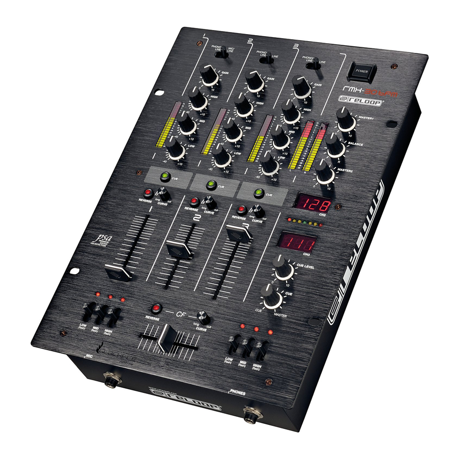
Overview of the device
Controls

Designation:
- Signal input selector for channels 1 to 3
- Gain control for channels 1 to 3
- 3-fold equalizer for channels 1 to 3
- Modulation LEDs for channels 1 to 3
- Cue switch for channels 1 to 3
- Linefader reverse switches for channels 1 to 3
- Linefader curve controls for channels 1 to 3
- Linefaders for channels 1 to 3
- Crossfader reverse switch
- Crossfader curve controls
- Crossfader
- Kill switch units for both crossfader channels
- Cue-Master control
- Volume control for headphones output
- BPM displays
- Beat Offset LED
- Volume control master output 2
- Balance control master output
- Volume control master output
- Modulation LED for master signal
- ON/OFF switch
Front panel

- Input jack for mic (XLR/ 6.3 mm jack plug)
- Output jack for headphones (6.3 mm jack plug)
Rear Panel

- Input jack for external power pack
- Master 1 output jacks (cinch)
- Master 2 output jacks (cinch)
- REC output jacks (cinch)
- Input jacks for channels 1 to 3 (cinch)
- Phono/line change-over for channels 1 to 3
- GND grounding screws
- Master 1 output jacks (6,3 mm jack plug)
Connections
- Connect your line sources (CD player, MiniDisc, DAT, etc.) andyour turntables with the input jacks for channels 1 to 3 -28-. If you wish to connect (a) turntable(s) to the "Phono" jacks switch the phono/line change-over switches to the "Phono"position. If you intend to hook up (a) line source(s) to these jacks simply switch the phono/line change-over switch -29- to the "Line"-position.

When operating the phono/line change-over switches always make sure that the unit is switched of.
- Connect the ground cable of your turntables with the respective GND ground screw -30-.
- Connect your microphone with the Mic input jack -22-.
- Connect your headphones with the output jack for headphones
- Connect your main unit according to your requirements with the Master 1 output jacks -25- (cinch) or with the Master 1 output jacks -31- (6,3 mm jack plug).
- Connect your monitor unit with the Master 2 output jacks -26-.
- Connect the recording equipment of your choice with the REC output jacks -27-.
- Hook up the external power pack with the respective input -24-.
Operation
- Power on
After making all connections turn on the power with the ON/OFF switch -21-. - Signal selector
The signal input selector -1- allows you to choose between line, phono and mic source for channels 1 to 3. Please observe the designation of the individual signal input selectors as well as the positions of the Phono/line change-over switches -29-. - Gain
The gain control -2- sets the input volume for channels 1 to 3. - Equalizer
The equalizer for channels 1 to 3 -3- sets the bass, middle and treble. - Pre-listening
The Cue switches for channels 1 to 3 -5- select the channel/s for pre-listening in your headphones. The channel selected with the Cue switch is illuminated on the respective LED. The Cue Master control -13- infinitely adjusts the master signal for the pre-listened signal. In "Cue" position only the pre-listened signal can be heard, in "Master" position only the master signal can be heard. This allows the advance simulation of a mix in the headphones. The control -14- regulates the volume level of the headphones. - Channels 1 to 3
The linefaders -8- set the output volume for channels 1 to 3. Press the linefader reverse switches -6- to reverse the respective linefader assignment. The progression of the linefaders can be set with the linefader curve controls -7-; press on the respective knob to lift it up. Turning clockwise "sharpens" the linefader, i.e. ideal for scratching and cutting; turning counter clockwise "softens" the linefader, making it ideal for long mixes. Now you can depress the knob again. - Crossfader
Use the crossfader -11- to switch between the signal of channel 2 and 3. Press the crossfader reverse switch -9- to reverse the crossfader assignment. The progression of the crossfader can be set with the crossfader curve control -10-; press on the knob to lift it up. Turning clockwise "sharpens" the crossfader, i.e. ideal for scratching and cutting; turning counter clockwise "softens" the crossfader, making it ideal for long mixes. Now you can depress the knob again. - Mic
Set the signal input selector for channel 1 -1- to the right position "Mic/Line" to activate the microphone. Now you can use the gain control for channel 1 -2-, the 3-fold equalizer for channel 1 -3- and the linefader for channel 1 -8- to adjust the tone as well as the input and output volume.
NOTE!
If you have connected a line source to the channel 1 "Line" input jack -28- and play it back, the line signal will be heard simultaneously together with the microphone-signal. - Modulation
The modulation LEDs -4- indicate the output level of channels 1 to 3. Select the channel volumes with the linefaders for channels 1 to 3 -8- with the 3-fold equalizers for channels 1 to 3 -3-, as well as with the gain control for channels 1 to 3 -2- as such that the red LEDs flash rarely; this prevents overmodulation of the channels. The modulation LED -20indicates the output level of the right and left channel of the Master output. Select the output volume with the volume control -19- as such that the red LEDs flash rarely. This prevents overmodulation of the Master output 1. - Kill Switches
The Kill Switch units -12- enable instant suppression of the different frequencies (bass, middle, treble). The LED indicates deactivated frequencies. The left Kill Switch unit controls the left crossfader channel; the right controls the right crossfader channel. - BPM Displays
The BPM displays -15- automatically indicate the beats of the signal sources in "Beats per Minute" (BPM). The displays indicate "- -" instead of beats if there are no audio signals, or if the audio signals are too faint, or if the beats are not countable.
NOTE!
The Reloop RMX-30 BPM can not count the beats if there is no continuous rhythmic structure or if the beats are too faint to be distinguished from the remainder of the track for identification as a rhythmic element. 4/4 beats are ideal for the Reloop RMX-30 BPM. - Beat Offset LED
The Beat Offset LED -16- monitor the balancing of the beats in the event of equivalent BPM of the two signal sources. The Beat Offset LED is divided into three ranges:- Red: Beats are offset.
- Yellow: Beats almost balanced.
- Green: Balanced beats.
NOTE!
The Beat Offset LED is not indicative if the BPM of the two signal sources are not the same. The Beat-Offset LED does not illuminate if the difference between the two signal sources exceeds 11 BPM.
- Outputs
The Master control -19- sets the output volume of the Master output 1 -25- / -31-. The balance control -18- selects the volume ratio between right and left output signal. In centre position the volume of both channels is the same. The Master 2 control -17- sets the output volume of the Master 2 output -26-.
NOTE!
The position of the volume control -19- does not affect the REC output -27-. Only adjustments to the gain controls -2-, linefaders -8-, equalizers -3- and balance control -18- affect the recording.
Technical information
GDT GmbH did not test the following manufacturers' specification for plausibility and accuracy:
| Inputs | Phono: 3 mV/47 kW, Line: 200 mV/10 kW, Mic: 2 mV/3 kW |
| Outputs | Master: 1 & 2: 1 V/1 kW (MAX. 8 V), Headphones: 0,7 V/33 W (MAX. 1.7 V), Record: 398 mV/1 kW (MAX. 2.5 V) |
| Frequency response | 20 Hz - 20KHz, +2/-3 dB |
| Frequency high peak / low peak | +10 dB/- 35 dB |
| Distortion | 0.05% |
| S/N ratio | Phono: < -65 dB, Line: < -77 dB, Mic: < -60 dB |
| Dimensions | 254 x 355 x 87 mm |
| Weight | 3.8 kg |
Reloop Distribution
GDT GmbH, Hafenstr. 64, 48153 Münster/Germany Fax +49.251.6099368

Documents / ResourcesDownload manual
Here you can download full pdf version of manual, it may contain additional safety instructions, warranty information, FCC rules, etc.
Advertisement


Need help?
Do you have a question about the RMX-30 BPM and is the answer not in the manual?
Questions and answers