Endress+Hauser OXY5500 Operating Instructions Manual
Gas analyzer
Hide thumbs
Also See for OXY5500:
- Operating instruction (146 pages) ,
- Overview manual (56 pages) ,
- Operating instructions manual (37 pages)

Related Manuals for Endress+Hauser OXY5500


Summary of Contents for Endress+Hauser OXY5500
- Page 1 BA02195C/66/EN/02.22 70197321 Products Solutions Services Operating Instructions OXY5500 Gas Analyzer ATEX/IECEx/UKEX: Zone 2 cCSAus: Class I, Division 2...
- Page 2 Operating Instructions OXY5500 Gas Analyzer Endress+Hauser...
-
Page 3: Table Of Contents
2.5 Documents provided with the analyzer ....7 Modbus communication ....55 2.6 Manufacturer address ..........7 6.1 Protocol definition ..........55 2.7 About the OXY5500 analyzer ........ 7 6.2 Examples ..............64 2.8 Getting familiar with the analyzer ......7 Appendix A: Specifications ....66 2.9 Safety guidelines ........... -
Page 4: About This Document
UKSI 2016:1107 for products sold on the market in Great Britain (England, Wales and Scotland). Table 2. Symbols U.S. export compliance The policy of Endress+Hauser is strict compliance with U.S. export control laws as detailed in the website of the Bureau of Industry and Security at the U.S. Department of Commerce. -
Page 5: Introduction
"Table of Contents". There are a number of options and accessories available for the OXY5500 analyzers. This manual has been written to address the most common options and accessories. Images, tables, and charts have been included to provide a visual understanding of the analyzer and its functions. -
Page 6: General Warnings And Cautions
Operating Instructions OXY5500 Gas Analyzer General warnings and cautions Instructional icons are provided in this manual to alert the user of potential hazards, important information, and valuable tips. Following are the symbols and associated warning and caution types to observe when servicing the analyzer. -
Page 7: Documents Provided With The Analyzer
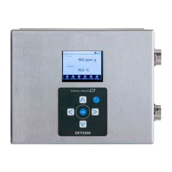
II 3 G, Ex ec IIC T3 Gc IP66. The OXY5500 is designed for three types of measurement ranges: 0 to 1000 ppmv, 0 to 5% O2, and 0 to 20% O2. This analyzer was specifically designed for gas measurements using a flow through fiber-optic oxygen sensor mounted in a 1/4 in. - Page 8 Analyzer Power Port RTD Probe (pt100) Chassis Ground Stud Figure 1. OXY5500 analyzer Inside the cabinet is the electro-optical module that provides power and other connections to the analyzer. Refer to Figure 3 for an internal view of the analyzer.
- Page 9 Figure 4. OXY5500 probe sensor spot Endress+Hauser’s fiber-optic oxygen sensors are made with 2 mm polymer optical fibers. The sensing portion is a 4 mm stainless steel probe. As a standard, the probe is mounted in a 1/4 in. Swagelok Union Tee using a 1/4 in. x 4 mm adapter as shown in Figure 5.
-
Page 10: Safety Guidelines
Figure 6. Principle of dynamic quenching of luminescence by molecular oxygen Safety guidelines Please read these instructions and the OXY5500 Safety Manual (P/N XA02754C) carefully before working with this instrument. All functions of this device has been carefully tested and comply with safety requirements, prior to leaving the factory. -
Page 11: Safety
OXY5500 Gas Analyzer Operating Instructions Safety Potential risks affecting personnel This section addresses the appropriate actions to undertake when faced with hazardous situations before or during service of the analyzer. It is not possible to list all potential hazards within this document. The user is responsible for identifying and mitigating any potential hazards present when servicing the analyzer. -
Page 12: Installation
OXY5500 Gas Analyzer Installation This section describes the processes used to install and setup your OXY5500 analyzer. Once the analyzer arrives, fully examine the contents before installing the unit. Endress+Hauser Class I Division 2 analyzers use a non-incendive protection method and Zone 2 uses an increased safety ec protection method;... -
Page 13: Hardware And Tools For Installation
Needle-nose pliers Analyzer mounting The OXY5500 analyzer is manufactured for wall or Unistrut® (or equivalent) metal framing installations. Depending on your application and configuration, the analyzer will come mounted on a plate or Unistrut frame. Refer to Appendix A for drawings with detailed wall mounting dimensions. -
Page 14: Connecting Electrical Power To The Analyzer
The OXY5500 is able to interface with either AC or DC power connections. The OXY5500 is available in power options of either 240 VAC or 9 to 30 VDC (CSA), or 18 to 30 VDC (IEC/ATEX/UKEX). The OXY5500 can be powered by an DC source via connection directly to the terminal of the DC/DC converter terminals. - Page 15 Connecting electrical power to the analyzer Open the OXY5500 analyzer electronics enclosure door. Take care not to disturb the electrical assembly inside. Hazardous voltage and risk of electric shock. Failure to properly ground the analyzer may create a high-voltage shock hazard.
-
Page 16: Analyzer Connections
OXY5500 Gas Analyzer Analyzer connections The fiber optic oxygen cable to the SMA connector, located at the bottom of the OXY5500, will be installed at the factory. Additional connectors are available as shown in Figure 9. RS-232/RS-485 Interface: The unit has standard RS-232 communication via Modbus protocol. Use care in making connections as described in Modbus Communication →... - Page 17 OXY5500 Gas Analyzer Operating Instructions 4.9.1 Connecting the analog outputs/analog inputs Disconnect power from the analyzer and open the electronics enclosure cover. Take care not to disturb the electrical assembly inside. Run conduit or rated armor cable with the appropriate cable glands (minimum Exe rated) from the analog outputs/inputs receiving station to the conduit hub in the right outside corner of the electronics enclosure.
- Page 18 Operating Instructions OXY5500 Gas Analyzer Label Description Function L-S1 Relay output, switch #1 (400V/250mA; R = max 8 Ohm) General Fault Alarm; normally closed L-S1 Relay output, switch #1 (400V/250mA; R = max 8 Ohm) L-S2 Relay output, switch #2 (400V/250mA; R = max 8 Ohm) Concentration Alarm;...
-
Page 19: Operation
Operation The instructions provided in this chapter should be used to start up, configure, and operate the OXY5500. On the face of the analyzer is an LCD with programming and data readouts. Refer to Figure 1 for an external view of the analyzer with descriptions. - Page 20 Click Menu to access the MAIN MENU screen. Refer to Figure 14 for a view of the MENU MAP that outlines the OXY5500 software structure. This section gin with a review of the top level menu screens (shown in grey boxes in the Menu Map) and then continue with an overview of the accessible screens available from each menu screen.
-
Page 21: Measurement Menu
OXY5500 Gas Analyzer Operating Instructions Figure 14. OXY5500 software menu map Measurement menu Selecting Measurement from the MAIN MENU screen displays the currently measured values and measurement settings. Refer to Figure 15. Figure 15. Main menu screen - Measurement selected Views can be selected for simple, detailed, or graphical presentations of the measurements. -
Page 22: Measurement Settings (Meas. Settings) Menu
Operating Instructions OXY5500 Gas Analyzer Measurement settings (Meas. settings) menu General measurement setting changes are performed in the MEASUREMENT SETTINGS menu. If the measurement settings are not changed, the settings from the last measurement will be applied. The Measurement Settings (Meas. Settings) window is selected from the MAIN MENU screen. Refer to Figure 16. -
Page 23: Device Settings Menu
OXY5500 Gas Analyzer Operating Instructions 5.4.1 To enter editing mode Click OK to enter editing mode. Change the setting or value (one digit at a time) by clicking the Arrow buttons. Click OK again to save the changes. 5.4.2 To exit editing mode Click Menu to cancel and exit. -
Page 24: Digitals Menu
Refer to Change parameters → and Calibrating the analyzer on → for more information about these functions. Digitals menu From the MAIN MENU, select Digitals to change the digital connection setting of the OXY5500. Refer to Figure 22. Figure 22. Main menu screen - Digitals selected Before displaying the DIGITALS screen, a message window displays requesting confirmation to abort the currently running operation. -
Page 25: Analog Output Settings (Analogues) Menu
OXY5500 Gas Analyzer Operating Instructions 5.7.1 To enter editing mode Click OK to enter editing mode. Change the setting or value (one digit at a time) using the Up and Down Arrow buttons. Click OK again to save editing changes. -
Page 26: Measurement Menu Options
Operating Instructions OXY5500 Gas Analyzer 5.8.2 To exit editing mode Click Menu to cancel and exit editing mode. All changes will be applied after the next measurement period. Measurement menu options Selecting Measurement from the MAIN MENU will open the SIMPLE screen. The DETAILS or GRAPH screens can be selected from the SIMPLE screen. - Page 27 OXY5500 Gas Analyzer Operating Instructions Figure 28. Error message - Sensor cannot be detected The oxygen values are displayed in the following units: • For OP-3 sensor: %O2 • For OP-6 sensor: %O2, ppmv • For OP-9 sensor: ppmv Click the Up and Down Arrow buttons to change the oxygen unit on the display. The last measurement value shown in the respective oxygen unit immediately.
- Page 28 Operating Instructions OXY5500 Gas Analyzer • General: Here the Sensor type of the currently connected oxygen sensor is displayed. The currently measured or manually set Pressure value is also displayed in the General box. For automatic measurement, the display will show the interpreted pressure value from the 4-20mA input. If no pressure sensor is connected, the display will read 1013 mbar.
- Page 29 OXY5500 Gas Analyzer Operating Instructions 5.9.4 Graph screen The oxygen values of the current measurement session are displayed in a graph; the last measurement value of the Current Measurement is shown at the top of the screen. Refer to Figure 30.
-
Page 30: Measurement Settings (Meas. Settings) Menu Options
Operating Instructions OXY5500 Gas Analyzer 5.10 Measurement settings (Meas. settings) menu options After selecting Meas. Settings from the MAIN MENU, the MEASUREMENT SETTINGS window displays. The analyzer temperature compensation, pressure compensation, interval, and logging and data management options are accessed from this screen. - Page 31 Figure 33. Measurement settings screen - Pressure compensation If the OXY5500 was purchased with a pressure sensor, the analyzer will be configured to use the pressure sensor from the factory. If the pressure sensor is purchased separately, refer to the following steps for configuring the pressure sensor.
- Page 32 The Interval sampling rate determines the frequency for the sensor calibration. For example, a sensor with an Interval sampling rate of 30 seconds would produce 100,000 measurement points at 34.7 days. Endress+Hauser recommends 35 days as a starting point for re-calibration or as the application requires it. Refer to Table 9 below and Calibrating the analyzer →...
- Page 33 OXY5500 Gas Analyzer Operating Instructions Figure 36. Measurement browser - List of measurement files • Use the Up and Down Arrow buttons to navigate up or down the list. • Click OK to select the highlighted file. The new measurement data will be added to the existing file. The display will switch back to the measurement settings automatically.
-
Page 34: Device Settings Menu Options
5.11.1 Device settings screen This screen is used to change the general settings of the OXY5500. Refer to Figure 38. Date, Time, LED Intensity (User Signal Intensity), and Forced Zero settings are saved with every measurement in the respective measurement file. - Page 35 Alarm Signal Figure 40. Forced Zero alarm signal The OXY5500 requires regular calibration as discussed in Calibrating the analyzer → . Negative oxygen values which may be due to an inaccurate calibration are not displayed when Forced Zero is active.
- Page 36 OXY5500 Gas Analyzer 5.11.4 About screen The ABOUT screen provides the Serial Number, LED Status, and Firmware Version of the OXY5500. Refer to Figure Figure 41. About screen Make sure to have the analyzer information found in the ABOUT screen before contacting Service → .
-
Page 37: Sensor Menu Options
OXY5500 Gas Analyzer Operating Instructions 5.12 Sensor menu options The option to change parameters, sensor type, or to calibrate the analyzer are accessed via the Sensor button on the MAIN MENU. 5.12.1 Change parameters Clicking the Change Parameters button in the SENSOR menu causes a message window to display with the question to abort the currently running measurement. - Page 38 Operating Instructions OXY5500 Gas Analyzer 5.12.4 Changing the sensor type If it is necessary to change the probe type in the field, change the sensor type (OP-3, OP-6, or OP-9) according to the sensor that is connected to the analyzer. The displayed sensor constants (dKSV1, dKSV2, dPhi1, dPhi2, f1, and m) will change according to the sensor type selected.
- Page 39 OXY5500 Gas Analyzer Operating Instructions 5.12.5 To manually change the sensor constants values Select the desired field and click OK. Click Next in the upper right corner of the screen, then click OK. The display will change to the CALIBRATION DATA screen. Refer to Figure 46. If a calibration was performed with a previously connected sensor, the data from that calibration is shown.
- Page 40 Select Manual to insert the changes to the calibration temperature manually. To proceed with the calibration, click Next at the top right of the screen followed by OK. Before starting the measurement, the OXY5500 must be calibrated. Refer to Calibrating the analyzer → . 5.12.9 Calibrating the analyzer Complete the calibration procedures in this section before starting the measurement.
- Page 41 5.12.11 Calibration gas connections to the OXY5500 analyzer Connecting the two calibration gas cylinders to a three-way valve will minimize the OXY5500 exposure to ambient oxygen. This process will help reduce the calibration time of the analyzer. The instruction below are for analyzers with and without integrated sample conditioning systems.
-
Page 42: Purging The Cylinder Pressure Regulators And Analyzer
Reducers Port Connector OXY5500 Probe Figure 50. Connection locations 5.12.13 Connecting the gas inlet for analyzers with Endress+Hauser’s sample conditioning system (SCS) Attach the Port Connector to the Endress+Hauser analyzer SCS enclosure. Connect the three-way valve to the port connector. - Page 43 OXY5500 Gas Analyzer Operating Instructions Close the cylinder valve and crack the dual stage pressure regulator outlet valve. Allow the gas to discharge until both the primary and secondary regulator pressure gases approach zero. Close the dual stage pressure regulator outlet valve prior to releasing the last amount of gas pressure.
- Page 44 Operating Instructions OXY5500 Gas Analyzer 5.13.2 Performing a two-point calibration To perform a two-point calibration with the connected oxygen sensor, begin by selecting the screens below. When completed, continue with the procedure detailed in “Calibrating the analyzer” on page 53.
- Page 45 2 years provided the sensor material is stored in the original packaging. Table 12. Calibration gas specifications In the upper section of the main screen, the Present Values measured by the OXY5500 are displayed. Refer to Figure Figure 56. Calibration screen...
- Page 46 Operating Instructions OXY5500 Gas Analyzer 5.13.6 Setting the first calibration point Cal0 Flow Cal0 gas to sensor for the first calibration point. Refer to Table 12 for Cal 0 gas specifications. Click Start to the left of the Cal0 value.
- Page 47 OXY5500 Gas Analyzer Operating Instructions Figure 58. Message window - Stop measurements for calibration Select Yes and stop the measurement to move to the CALIBRATION screen. Use the Up and Down Arrow buttons to navigate between input fields. 5.13.11 To enter editing mode Click OK.
- Page 48 Operating Instructions OXY5500 Gas Analyzer 5.13.14 Setting the temperature for RATA calculation • Select Auto to measure the temperature for RATA calculation with the RTD probe (Pt100 temperature sensor). • Select Manual if the temperature for RATA calculation is known. Temperature values can be input in °C, °F, or K.
-
Page 49: Digitals Menu Options
OXY5500 Gas Analyzer Operating Instructions 5.14 Digitals menu options Set RS-232, RS-485, and TCP/IP configurations from the Digitals button on the MAIN MENU. 5.14.1 RS-232 settings Use this screen to set the baud rate of the RS-232 channel. Refer to Figure 61. -
Page 50: Analog Output Settings (Analogues) Menu Options
Operating Instructions OXY5500 Gas Analyzer 5.14.3 TCP/IP settings Use this screen to set TCP/IP. Refer to Figure 63. Figure 63. Digitals - TCP/IP settings • If DHCP is selected, the IP and Subnet Mask will be assigned by the DHCP server and therefore are not editable. - Page 51 OXY5500 Gas Analyzer Operating Instructions The Mode of Port1 and Port2 can be set to one of the following: • Off: No input reading or output writing. • Linear: High and low value that has been set to correspond to 4mA and 20ma. Values between these two settings will be calculated linearly.
- Page 52 Operating Instructions OXY5500 Gas Analyzer Figure 67. 4-20mA values for mode “Linear” • Bilinear: The High Value, Mid Value, and Low Value can be entered. Refer to Figure 68. The units are the same as those used in Linear mode. The values will be used for calculating the output or input value on the next measurement.
- Page 53 The procedure for calibrating the input is similar to the output procedure noted above. Use the following steps to calibrate the input. Refer to Figure 71. Apply a low current to the OXY5500. Enter this value in the Reference column in the 1st Point row.
- Page 54 OXY5500 Gas Analyzer Figure 71. Analogues - 4-20mA input calibration Apply a higher value to the OXY5500. Enter this value in the Reference column in the 2nd Point row. Click Set next to the 2nd Point when the reading is steady.
-
Page 55: Modbus Communication
This chapter covers the protocols, formats, and register data used to communicate with the OXY5500. Protocol definition 6.1.1... - Page 56 6 (Slave device busy): This code appears when there is an “active” USB connection (communication via software is active). 6.1.5 Different communication channels The OXY5500 has multiple ways to read and set its settings and measurement values: • Modbus Communication RS-485 RS-232 •...
- Page 57 OXY5500 Gas Analyzer Operating Instructions 6.1.6 Holding registers Refer to Table 14 for table register definitions. When reviewing the table, it is important to remember: • The register addresses referred to in Table 14 show the first address of multiple addresses available per register (see “Size”...
- Page 58 Operating Instructions OXY5500 Gas Analyzer Register Name Address Size Variable Type Description Write Access Baud Rate Minimum 4117 Int32 Minimum code for baud rate RS-232 Baud Rate Maximum 4119 Int32 Maximum code for baud rate RS-232 Parity RS-232 4121 Int32...
- Page 59 OXY5500 Gas Analyzer Operating Instructions Register Name Address Size Variable Type Description Write Access 4-20mA Input 5633 Int32 This register is reserved for future use. Interface 4-20mA Input 5637 Int32 Code for 4-20mA Port1 Output Interface where: Channel 0x02 = Pressure.3...
- Page 60 Operating Instructions OXY5500 Gas Analyzer Register Name Address Size Variable Type Description Write Access O2-2nd Unit 5535 Int32 The unit for the O2-2nd value, where: 0x4000.0000 = ppmv 0x0000.0010 = % O2 Ethernet Obtain IP 5675 Int32 Activates or deactivates DHCP. Entering “1” will Mode obtain IP automatically.
- Page 61 OXY5500 Gas Analyzer Operating Instructions Description Interval on/off (delete to turn off, set to turn on) Status-Bit: Set when a measurement is currently performed. will be deleted after completing the measurement. Setting this bit does not trigger any action. Start measurement (single scan or continuous)
- Page 62 Operating Instructions OXY5500 Gas Analyzer It is not necessary to read out all 14 registers. For simple applications, reading out registers 9 to 14 (starting with Register 4903) may be all that is required. 2N Value Error No RTD (Pt100)
- Page 63 Always Table 27. Oxygen units for various output, sensor, and measurement mode configuration Endress+Hauser recommends deactivating the current measurement before changing any settings. The device will hold its last analog output value until the next measurement. 6.1.16 Ethernet IP...
-
Page 64: Examples
Operating Instructions OXY5500 Gas Analyzer Examples 6.2.1 Configuration of a continuous measurement Precondition: Sensor is connected, and sensor constants and calibration values are already set up correctly (OP-9). The goal for this configuration is a continuous measurement with a 1-minute interval with the pressure sensor and RTD (Pt100) are deactivated. - Page 65 OXY5500 Gas Analyzer Operating Instructions 6.2.3 1-Point calibration of an OP-9 sensor • Precondition: Sensor is connected and put in a low oxygen environment. Sensor constants are already set correctly (OP-9). The goal for this example is to calibrate the oxygen sensor.
-
Page 66: Appendix A: Specifications
II 3 G, Ex ec IIC T3 Gc IP66 NOTE: Certification applies to the analyzer only. The enclosure versions of this product are considered accessories for the product and not included as part of the certification. Table 35. OXY5500 analyzer specifications Endress+Hauser... -
Page 67: Technical Notes
OXY5500 Gas Analyzer Operating Instructions Probe assemblies and other such equipment required for analyzer operation must meet with all manufacturer specifications. Technical notes • ANALYZER ENCLOSURE: The enclosure and fittings are designed for IP66/Type 4X ratings. In order to maintain this rating, all connections must be made with proper hardware and adhering to suggested procedures. - Page 68 Operating Instructions OXY5500 Gas Analyzer Figure 72. Outline and mounting dimensions - panel mount Endress+Hauser...
- Page 69 OXY5500 Gas Analyzer Operating Instructions Figure 73. Interconnect diagram (AC) Endress+Hauser...
- Page 70 Operating Instructions OXY5500 Gas Analyzer Figure 74. Interconnect diagram (DC) Endress+Hauser...
-
Page 71: Spare Parts
Operating Instructions Spare parts Below is a list of spare parts for the OXY5500 Optical Oxygen Analyzer with recommended quantities for 2 years of operation. Not all parts listed are included on every analyzer. When ordering, please specify the system serial number to ensure that the correct parts are identified. - Page 72 Part Number Description 2 YR QTY General BA02195C OXY5500 Operating Instruction, additional copies − BA02196C OXY5500 Sample Conditioning System (SCS) Operating Instruction, additional copies − XA02754C OXY5500 Safety Instruction, additional copies − SD02868C OXY5500 Service Software Operation Instruction, additional copies −...
-
Page 73: Appendix B: Maintenance And Troubleshooting
OXY5500 Gas Analyzer Operating Instructions Appendix B: Maintenance and troubleshooting The OXY5500 is a maintenance-free instrument, although some components may need cleaning or replacement. This chapter contains instruction for cleaning, replacement, and general troubleshooting information. Optical output The SMA connector is a high precision optical component. For optimal performance, keep it dry and clean. Always use the rubber cap to close the output when not in use. - Page 74 Operating Instructions OXY5500 Gas Analyzer 8.4.1 Replacing the fuse Turn off power to the analyzer and open the enclosure door using a standard flathead screwdriver to unlatch the lock. Using a flat-head screwdriver (or comparable), remove the cover from the fuse enclosure. Refer to Figure 75.
-
Page 75: Replacing The Electro-Optical Module
Operating Instructions Replacing the electro-optical module Use the following procedure to replace and install the electro-optical module in the OXY5500 analyzer. Photographs shown in this instruction are used to provide a clearer illustration of the required steps only. DO NOT REMOVE the base plate from the analyzer enclosure to complete this instruction. -
Page 76: Installing/Replacing The Pressure Sensor
Close the analyzer enclosure door. Installing/replacing the pressure sensor The pressure sensor is optional on the OXY5500 analyzer. Use this procedure to install or replace the pressure sensor. Refer to the procedure called Installing the pressure sensor → and Spare parts → for the pressure sensor kit part number to install this option. - Page 77 Remove the tubing between the pressure sensor and T-fitting. Refer to Figure 81. Figure 81. Removing the tubing Loosen both hinge screws from the OXY5500 analyzer enclosure and open the door. Disconnect the red and black wires labeled “psens-” and “psens+” from terminal block TB2 using the mini screwdriver as shown in Figure 82.
-
Page 78: Removing And Replacing The Oxygen Probe
Remove the new pressure sensor from the bag and insert into the opening with the green sealing washer with the same orientation as the one removed. Secure the panel nut to the top of the pressure sensor inside the OXY5500 enclosure. Tighten the panel nut sufficiently to avoid possible leaks from entering the analyzer enclosure. - Page 79 OXY5500 Gas Analyzer Operating Instructions Using an adjustable wrench, loosen the cable gland cap on the panel by turning “up” toward the analyzer. Do not remove cable gland cap. Refer to Figure 84. Figure 84. Loosen the cable gland cap Remove the tube nut on the panel using a 1/2 in.
- Page 80 Operating Instructions OXY5500 Gas Analyzer Remove the conduit clamp screw with a Philips screwdriver. Refer to Figure 87. Figure 87. Remove conduit clamp Turn the conduit bracket parallel to the panel and carefully disengage the probe from the Tee union (panel side).
- Page 81 OXY5500 Gas Analyzer Operating Instructions Loosen the connector nut on the probe at the SMA connector inside the analyzer enclosure. Refer to Figure 90. Oxygen Probe and SMA Connector Nut Tee Union Figure 90. Remove connector nut (analyzer side) Carefully pull the probe out through the conduit and discard.
-
Page 82: Correcting Error Codes
If measurement is conducted without temperature compensation, bear in mind that the OXY5500 only measures correctly if the sample temperature is constant during measurement and the temperature is the same as the entry at the beginning of the measurement. -
Page 83: Performance Improvement
3-way valve connected to the test gas enabling the user to switch back and forth between bottles. This can assist in verifying proper operation. 8.11 Troubleshooting Refer to Table 39 for frequently asked questions related to troubleshooting the OXY5500 before contacting the service department. To contact the service department, refer to “Service” in the next section. Indication Suspected Cause... -
Page 84: Packing And Storage
If returning the analyzer to the factory, complete the Decontamination Form provided by Endress+Hauser (refer to "Service repair order") and attach to the outside of the shipping package as instructed before shipping. -
Page 85: Storage
Warranty For a period of 18 months from date of shipment or 12 months in operation, whichever comes first, Endress+Hauser warrants that all products sold by it shall be free from defects in material and workmanship under normal use and service when correctly installed and maintained. - Page 86 Operating Instructions OXY5500 Gas Analyzer www.addresses.endress.com Endress+Hauser...
Need help?
Do you have a question about the OXY5500 and is the answer not in the manual?
Questions and answers