Table of Contents
Advertisement
Quick Links
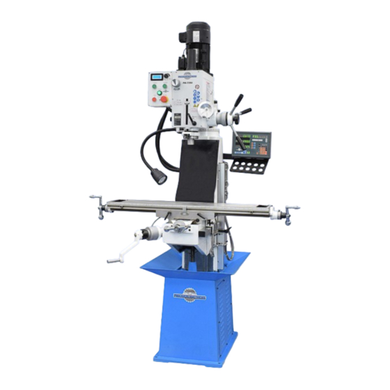
PM-739 M-V Milling Machine
Knee-mill features in a compact format: fixed head height, adjustable table height
Choice of 6-speed gearbox PM-739M or variable-speed drive PM-739V
220V single phase supply, 2HP motor
Heavy HT200 cast-iron construction
Exceptional spindle height over table, 19-1/2" max
Quill DRO for precise downfeed measurement
Optional factory-installed 3-axis DRO
Weight, including cast iron stand 1100 lb net
PM-739M
6-speed gearbox, 90 to
1970 rpm. Shown with
optional 3-axis DRO.
PM-739V
Variable-speed drive, 75
to 2500 rpm. Shown with
optional 3-axis DRO.
Copyright © 2023 Quality Machine Tools, LLC
PM-739M&V 2023-06
1
Advertisement
Table of Contents

Related Manuals for Precision matthews PM-739M


Summary of Contents for Precision matthews PM-739M
- Page 1 PM-739 M-V Milling Machine Knee-mill features in a compact format: fixed head height, adjustable table height Choice of 6-speed gearbox PM-739M or variable-speed drive PM-739V 220V single phase supply, 2HP motor Heavy HT200 cast-iron construction Exceptional spindle height over table, 19-1/2” max...
- Page 2 (1) and left-to-right (2) axes — very helpful when precise tramming is called for. Fine adjustment of the forward tilt is facilitated by the worm screw shown in (3) above. Copyright © 2023 Quality Machine Tools, LLC PM-739M&V 2023-06...
- Page 3 4 This manual contains essential safety advice on the proper setup, operation, maintenance, and ser- vice of PM-739M and PM-739V milling machines. Failure to read, understand and follow the manual may result in property damage or serious personal injury.
-
Page 4: Section 1 Features & Specifications
Section 1 FEATURES & SPECIFICATIONS MODEL PM-739M and PM-739V Milling Machines General information These machines are exclusive to PM, and completely new to the market—compact as a bench-mill, but with knee- mill features such as a vertically-adjustable table. Also, the headstock can be precisely tilted in two axes, side to side and—uniquely—front-to-back, a capability that allows perfect alignment (tramming) of the spindle relative to... - Page 5 Motor M: 2 HP single-phase ac V: 2HP three- phase ac (from VFD) LO range: 90, 210, 345 Spindle speed PM-739M, two ranges HI range: 670, 1180, 1970 Continuously variable, LO: 75 to 435 rpm Spindle speed PM-739V, two ranges...
-
Page 6: Section 2 Installation
If available, use a forklift with a basket-style web sling to lift and move the mill, Figure 2-2. Alternatively, a 1" di- ameter steel rod can be inserted into the hole at the top Figure 2-1A Floor drilling Copyright © 2023 Quality Machine Tools, LLC PM-739M&V 2023-06... - Page 7 In the suggest- ed procedure given here, the mill is lifted just enough to allow the pallet to be removed. Thereafter the engine hoist can be used to roll the mill. Copyright © 2023 Quality Machine Tools, LLC PM-739M&V 2023-06...
-
Page 8: Power-Up Procedure
6-15 or 6-20 plug on the mill power cord. Be sure the green/yellow ground wire is attached (it may be tagged PE = Protective Earth). Figure 2-5 Control panels: M model left, V model right Copyright © 2023 Quality Machine Tools, LLC PM-739M&V 2023-06... -
Page 9: Section 3 Using The Mill
● Clean the machine routinely – remove chips by brush or vacuum, not com- pressed air (which can force debris into the ways). No list of precautions can cover everything. You cannot be too careful! Copyright © 2023 Quality Machine Tools, LLC PM-739M&V 2023-06... - Page 10 Quill DRO Quill lock Down stop adjust Oiler Figure 3-1 PM-739M Controls DO NOT SHIFT GEARS WHEN MOTOR IS RUNNING. Allow the spindle to stop rotate the spindle forward and back while applying completely before shifting gears. light pressure on each lever, listening for the click as ●...
- Page 11 PM-739M WIRING DIAGRAM Copyright © 2023 Quality Machine Tools, LLC PM-739M&V 2023-06...
-
Page 12: Schematic Notes
A second contact of KM1 breaks the path to contactor KM2, preventing an attempt to reverse the motor through SB4 without first stopping the motor (SB2). Fuse FU1 Figure 3-3 PM-739M motor control box Copyright © 2023 Quality Machine Tools, LLC PM-739M&V 2023-06... - Page 13 PM-739 M and V DRIVE TRAINS COMPARED The 2-speed gearbox in the PM-739V is similar, except The PM-739M has a single-speed, single-phase 220V that the 2-3-1 shifter is replaced by fixed-speed inter- motor, driving the spindle through a 6-speed gearbox, mediate gears, Figure 3-8.
- Page 14 5. Turn the speed control, right of the display, fully disconnect. The E-STOP button is not momentary; counter clockwise. once in, it stays in until twisted clockwise. Copyright © 2023 Quality Machine Tools, LLC PM-739M&V 2023-06...
- Page 15 PM-739V WIRING DIAGRAM Copyright © 2023 Quality Machine Tools, LLC PM-739M&V 2023-06...
- Page 16 KA. This supplies power via the normally-closed STOP push button (SB3) to the FORWARD and REVERSE contactors continues to supply power to the motor when the push button Figure 3-8 PM-739V 2-speed gearbox Copyright © 2023 Quality Machine Tools, LLC PM-739M&V 2023-06...
- Page 17 A second contact of KM1 breaks the path to contactor KM2, preventing an attempt to reverse the motor through SB5 without first stopping the motor (SB3). Figure 3-10 PM-739V Motor control compartment Copyright © 2023 Quality Machine Tools, LLC PM-739M&V 2023-06...
-
Page 18: Tools Required
R8 tooling. It can sometimes be helpful to lock the top end of the spindle with a 6-spline wrench (available fully unscrew and remove the drawbar with the other hand. from most machinery distributors), Figure 3-14. Copyright © 2023 Quality Machine Tools, LLC PM-739M&V 2023-06... -
Page 19: Moving The Table
Like Figure 3-18 Axis locks the X and Y axes, the Z axis has a graduated dial with 0.001" divisions, 0.1" per revolution. Copyright © 2023 Quality Machine Tools, LLC PM-739M&V 2023-06... - Page 20 The thumbscrew (arrowed) locks the When possible, operations calling for precise dial to the handwheel spindle. depth control (such as milling) should be done with the quill fully retracted into the headstock and locked. Copyright © 2023 Quality Machine Tools, LLC PM-739M&V 2023-06...
-
Page 21: Tapping Operations
50 on the dial opposite the datum; the spin- may let go without warning. (First-time tilting may also dle is now precisely 0.25” to the back of the refer- call for unusual effort on the wrench.) ence edge. Copyright © 2023 Quality Machine Tools, LLC PM-739M&V 2023-06... - Page 22 Use the indicator's relative mode to measure the angle be- tween the spindle and the surface of the workpiece. To set the headstock to a specified tilt angle, as opposed Figure 3-25 Shop-made indicator holder Copyright © 2023 Quality Machine Tools, LLC PM-739M&V 2023-06...
- Page 23 Most users aim for an end-to-end difference of not more precision vise. For the PM-739 a 4" vise is most suitable. than ± 0.001” over the width of the vise jaw. Copyright © 2023 Quality Machine Tools, LLC PM-739M&V 2023-06...
- Page 24 Figure 3-27 Vise keys installed on X-axis On most vises the keys can also be installed on the long axis. Figure 3-28 Shop-made vise key Vise slot 16 mm Copyright © 2023 Quality Machine Tools, LLC PM-739M&V 2023-06...
-
Page 25: Section 4 Maintenance
Before starting a work session, and every few hours ber way cover behind the table. The lower adjustment screw thereafter: for the Z axis is under the knee casting, below item (3). Copyright © 2023 Quality Machine Tools, LLC PM-739M&V 2023-06... - Page 26 The inner end of the spring is attached by a screw to the quill pinion shaft. If the spring is broken, contact Precision Matthews for a replacement and special in- structions. Increasing spring tension is a straightforward procedure, as follows: 1.
- Page 27 6. Unlock the quill to test the return spring function. Repeat Steps 2, 3 and 4 to achieve the desired spring force. To reduce spring force rotate the spring housing in Step 4 clockwise. Copyright © 2023 Quality Machine Tools, LLC PM-739M&V 2023-06...
-
Page 28: Section 5 Parts
Section 5 PARTS PM-739M&V COMMON COMPONENTS Fig 1 Copyright © 2023 Quality Machine Tools, LLC PM-739M&V 2023-06... - Page 29 PM-739M&V COMMON COMPONENTS Fig 1 Ref Description Part Ref Description Part Ref Description Part Base Z9680 Bush Z9723 Dial clutch Z9766 Base side cover Z9681 Elevation gear Z9724 Roll pin 5x35 Z9767 Button hd cap screw Z9682 Tabbed washer 20...
- Page 30 PM-739M MANUAL HEADSTOCK AND SPINDLE Fig 2 Copyright © 2023 Quality Machine Tools, LLC PM-739M&V 2023-06...
- Page 31 PM-739M MANUAL HEADSTOCK AND SPINDLE Fig 2 Ref Description Part Ref Description Part Ref Description Part head body Z9800 H-L gear shaft Z9843 return spring Z9886 head body cover Z9801 Gear 25T Z9844 clamping knob Z9887 int retaining ring Z9802...
- Page 32 PM-739V VARIABLE HEADSTOCK AND SPINDLE Fig 3 Copyright © 2023 Quality Machine Tools, LLC PM-739M&V 2023-06...
- Page 33 Z10009 For DRO parts 120 through 126 speed sensor unit Z9967 pinion shaft flange Z10010 see the PM-739M drawing and screw Z9968 return spring housing Z10011 parts list Copyright © 2023 Quality Machine Tools, LLC PM-739M&V 2023-06...
Need help?
Do you have a question about the PM-739M and is the answer not in the manual?
Questions and answers