Table of Contents
Advertisement
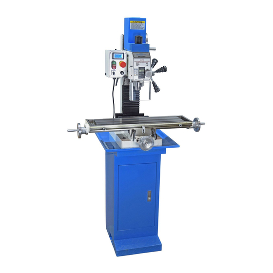
Model PM 25MV-BD Milling Machine
1 HP (750W) brushless dc motor, 110 Vac single phase power
Quiet belt drive, no gears
Variable spindle speed from 50 to 2500 rpm
Table size 27-1/2" x 7"
Quill DRO for precise downfeed measurement
Square column design, heavy cast iron construction
Options: welded steel stand/cabinet, 3-axis DRO
Weight 275 lb
PM 25MV-BD with optional 3-axis DRO
PM 25MV-BD with optional stand/cabinet
PM 25MV v9 2020-10
1
Copyright © 2020 Quality Machine Tools, LLC
Advertisement
Table of Contents

Related Manuals for Precision matthews PM 25MV-BD


Summary of Contents for Precision matthews PM 25MV-BD
- Page 1 Quill DRO for precise downfeed measurement Square column design, heavy cast iron construction Options: welded steel stand/cabinet, 3-axis DRO Weight 275 lb PM 25MV-BD with optional 3-axis DRO PM 25MV-BD with optional stand/cabinet PM 25MV v9 2020-10 Copyright © 2020 Quality Machine Tools, LLC...
- Page 2 This manual contains essential safety advice on the proper setup, operation, maintenance, and ser- vice of the PM 25MV-BD milling machine. Failure to read, understand and follow the manual may result in property damage or serious personal injury.
-
Page 3: Section 1 Installation
Setting up the mill The PM 25MV-BD is shipped in two packing cases, one for the machine and tray (and optional 3-axis DRO), one for the stand, if ordered. The following procedure makes use of an engine hoist, minimum weight rating 500 lb. - Page 4 Figure 1-2 Sling position Figure 1-3 Lowering the mill into position installation, use the four bolts M12 bolts supplied (the clockwise). 5. Press the Power button. The power lamp and the bolt locations are threaded.) Use lock + plain wash- tach display should light.
-
Page 5: Section 2 Features & Specifications
General information The PM 25MV-BD is a robust “square column” mill with R8 spindle and continuously-variable spindle speed up to 2500 rpm. It is designed for day-in, day-out use in the model shop. With a weight of 275 lbs it can handle far more than the typical small machine. - Page 6 PM25MV-BD SPECIFICATIONS Dimensions Approximate weight: Machine only 275 lb net, 320 lb shipping Welded steel stand 50 lb net, 54 lb shipping Size, including stand W 39 in. x D 20-1/2 in. x H 68-1/2 in. Stand footprint W 13-1/2 in. x D 16-1/2 in. Tray W 19-3/4 in.
- Page 7 Everyday precautions • This machine is designed for milling and drilling operations by experienced users familiar with metal-working hazards. • Untrained or unsupervised operators risk serious injury. • Wear ANSI-approved full-face or eye protection at all times when using the machine (everyday eyeglasses are not reliable protection against flying particles).
-
Page 8: Section 3 Using The Mill
O = Stop R = Reverse (ccw, looking down) SPINDLE SPEEDS The PM 25MV-BD is a belt-driven machine with two speed ranges, (L) 50-1250 rpm and (H)100-2500 rpm. To select a speed range, disconnect power, then remove the blue motor cover (4 screws). Loosen the socket head... - Page 9 INSTALLING AND REMOVING TOOLING The spindle and drawbar are designed for R-8 taper collets, drill chucks and other arbors with the standard 7/16”-20 internal thread. Two tools are required to install or remove R8 tooling: an 8 mm wrench for the square drawbar nut, and the supplied C-wrench which engages in flats at the bottom end of the spindle.
-
Page 10: Moving The Table
MOVING THE TABLE Conventionally, left-right movement of the table is said mill is not equipped with digital readouts (DROs), the to be along the X-axis (also called “longitudinal travel” table can be accurately positioned by counting whole or “traversing”). Front-back movement is on the Y-axis, turns and divisions, keeping leadscrew backlash in sometimes called “cross travel”. - Page 11 QUILL DOWNFEED The quill is controlled in two different ways, coarse and fine. In the drilling mode, coarse feed, the mill operates like a standard drill press with a 3-lever hub; lever action low- ers or raises the quill in the usual way by rack and pin- ion.
-
Page 12: Tapping Operations
POSITIONING BY COUNTING X / Y DIVISIONS For all spindle positioning operations, with or without DROs, avoid using the quill lock. vise, or otherwise clamped to the table, Figure 3-8. Why? On practically all vertical mills, including the heavi- er knee mills, locking the quill may offset the spindle by a 1. - Page 13 cured to the base casting by set screws in addition to the nuts shown in Figure 3-9. The set screws, if installed, are in a threaded hole on the 3-spoke handle side (right hand) of the headstock casting. The screws are installed in line, with the inner screw seated in a “safety groove”...
- Page 14 3. If the headstock has been tilted, reset it to the ap- Tramming calls for patience! Expect to tighten and re-check at least three times (simply tight- proximate zero degree position on the tilt scale, then ening the bolts can itself affect the tram). tighten the three nuts enough to avoid unexpected headstock movement.
- Page 15 Most users aim for an end-to-end difference of not more For routine milling operations the workpiece is held in a than ±0.001” over the width of the vise jaw. precision vise. For the PM 25MV-BD a 4” vise is most suitable. “Indicating” means checking the alignment of VISE KEYS the fixed (back) vise jaw relative to the axis of table mo- tion.
-
Page 16: Section 4 Maintenance
Section 4 MAINTENANCE means practically zero gap between the ways. Take time Unplug the 120V power cord before to understand exactly which are the bearing surfaces on any maintenance operation! the various dovetail surfaces; this is not obvious – some of the interfaces look like bearing surfaces, but are sim- Remove all machining debris and foreign ply narrow gaps. - Page 17 only if the entire machine is unbolted from the bench or stand, then: 1. Lifted by sling and engine hoist (see In- stallation, Section 1), or; 2. Tilted backward by pivoting on the back edge of the base casting. Both options are two-man procedures Figure 4-2 Z-axis gib adjustment, upper screw The lower screw is under the pleated way cover.
-
Page 18: Spindle Bearings
Overheating can be due to excessive grease, see above, or an over- tight spanner nut at the upper end of the spindle. Call Precision Matthews for guidance. SERVICING QUILL & SPINDLE In the normal use the quill assembly needs only oiling on its sliding surface. -
Page 19: Section 5 Parts
Section 5 PARTS Model PM25MV-BD ELECTRICAL SCHEMATIC Fig 1 PM 25MV v9 2020-10 Copyright © 2020 Quality Machine Tools, LLC... - Page 20 HEAD COMPONENTS Fig 2 There may be detail differences between this representative drawing and the machine as supplied PM 25MV v9 2020-10 Copyright © 2020 Quality Machine Tools, LLC...
- Page 21 HEAD COMPONENTS Fig 2 Ref Description Part Ref Description Part Spindle Z5209 Sleeve Z5247 Bearing seal Z5210 Worm gear Z5248 Roller bearing 32007 Z5211 Pinion shaft Z5249 Quill sleeve Z5212 Key: 4 x 12 Z5250 Roller bearing 32005 Z5213 Screw: M6 x 12, set Z5251 Spacer Z5214...
- Page 22 TABLE, COLUMN, & BASE COMPONENTS Fig 3 There may be detail differences between this representative drawing and the machine as supplied PM 25MV v9 2020-10 Copyright © 2020 Quality Machine Tools, LLC...
- Page 23 TABLE, COLUMN, & BASE COMPONENTS Fig 3 Ref Description Part Ref Description Part Base Z5285 Screw: M5 x 8 skt hd Z5325 Gib, Y-axis Z5286 Hose fitting (coolant) Z5326 Gib adjust screw Z5287 Z-axis pleated cover Z5327 Y-axis leadscrew Z5288 Support bracket Z5328 Key: flat, 5 x 16...
- Page 24 CHIP GUARD Fig 4 There may be detail differences between this representative drawing and the machine as supplied Dimensions in millimeters Ref Description Part Circlip Z5364 Switch box Z5365 Screw: M5 x 16 skt hd Z5366 Screw: M4 x 8, set, spc'l Z5367 D-shape shaft Z5368...
Need help?
Do you have a question about the PM 25MV-BD and is the answer not in the manual?
Questions and answers