Sign In
Upload
Download
Table of Contents
Contents
Add to my manuals
Delete from my manuals
Share
URL of this page:
HTML Link:
Bookmark this page
Add
Manual will be automatically added to "My Manuals"
Print this page
×
Bookmark added
×
Added to my manuals
Manuals
Brands
LG Manuals
Receiver
LHS-36MEC
Service manual
LG LHS-36MEC Service Manual
Dvd/cd receiver
Hide thumbs
1
Table Of Contents
2
3
4
5
6
7
8
9
10
11
12
13
14
15
16
17
18
19
20
21
22
23
24
25
26
27
28
29
30
31
32
33
34
35
36
37
38
39
40
41
42
43
44
45
46
47
48
49
50
51
52
53
54
55
56
57
58
59
60
61
62
63
64
65
66
67
page
of
67
Go
/
67
Contents
Table of Contents
Troubleshooting
Bookmarks
Table of Contents
Table of Contents
Section 1. General
Servicing Precautions
Esd Precautions
Service Information for Eeprom
Specifications
Section 2. Audio Part
Audio Troubleshooting Guide
Wiring Diagram
Block Diagram
Circuit Diagrams
Section 3. DVD & Amp Part
Electrical Troubleshooting Guide
DVD & Amp Circuit Diagrams
Section 4. Exploded Views
Advertisement
Quick Links
1
Section 1. General
2
Specifications
3
Section 2. Audio Part
4
Wiring Diagram
5
Circuit Diagrams
Download this manual
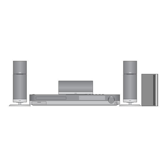
DVD/CD RECEIVER
SERVICE MANUAL
MODEL : LH-T3602(ME)/LHS-36MEC
LHS-36MEF/LHS-36MES/LHS-36MEW
P/NO : AFN31640715
SEPTEMBER, 2006
Table of
Contents
Previous
Page
Next
Page
1
2
3
4
5
Advertisement
Table of Contents
Troubleshooting
SECTION 2. AUDIO PART
8
SECTION 3. DVD & AMP PART
30
Need help?
Do you have a question about the LHS-36MEC and is the answer not in the manual?
Ask a question
Questions and answers
Related Manuals for LG LHS-36MEC
Dvd receiver LG LH-T3602ME Owner's Manual
(24 pages)
Receiver LG LST-4600A Installation And Setup Manual
Hd integrator box system (56 pages)
Receiver LG LHT734 Owner's Manual
Lg dvd receiver owner's manual (30 pages)
Receiver LG LHT799 Owner's Manual
Lg dvd receiver owner's manual (33 pages)
Receiver LG SH92SB-S Owner's Manual
Main unit, speakers (33 pages)
Receiver LG LHT854 - Home Theater System Service Manual
Dvd/cd receiver (65 pages)
Receiver LG LSS-3200A Service Manual
(103 pages)
Receiver LG LHT874 User Manual
5-disc dvd changer home theater system (28 pages)
Receiver LG LHT888 User Manual
Dvd home theater system (24 pages)
Receiver LG LH-T9654MB Owner's Manual
Lg lh-t9654mb: owners manual (29 pages)
Receiver LG LH-T1000 Owner's Manual
Dvd/cd receiver (36 pages)
Receiver LG LST-3410A Owner's Manual
Hdtv digital video recorder (72 pages)
Receiver LG LST-3100A Owner's Manual
Lg high definition television receiver owner's manual (44 pages)
Receiver LG LST-3100A Specifications
Advanced hd receiver (2 pages)
Receiver LG FE-6100CVE Service Manual
Dvd/cd receiver (101 pages)
Receiver LG LH-T363SD Owner's Manual
(26 pages)
This manual is also suitable for:
Lh-t3602(me)
Lhs-36mef
Lhs-36mes
Lhs-36mew
Table of Contents
Print
Rename the bookmark
Delete bookmark?
Delete from my manuals?
Login
Sign In
OR
Sign in with Facebook
Sign in with Google
Upload manual
Upload from disk
Upload from URL


Need help?
Do you have a question about the LHS-36MEC and is the answer not in the manual?
Questions and answers