Table of Contents
Advertisement
Quick Links
Advertisement
Table of Contents

Subscribe to Our Youtube Channel
Related Manuals for Teknatool nova 83700


Summary of Contents for Teknatool nova 83700
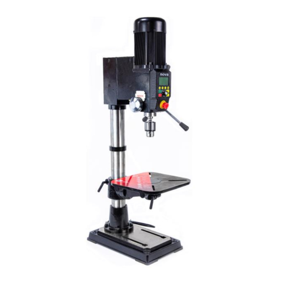
- Page 1 Viking DVR 16” Drill Press ™ Publication: 123-0420-029 Date: 2 April 2020 Bench Models: Floor Models: 83700 – USA 83705 – Canada 83701 – NZ/Australia 83706 – USA 83702 – Canada 83707 – Europe 83703 – Europe 83708 – UK 83704 –...
- Page 2 Contact Teknatool International Ltd Phone: (+64) 9 477 5600 Teknatool USA Phone: 727-954-3433 Customer Solutions For all worldwide Inquiries, Repairs or Services (issues must be in writing) Service@Teknatool.com Email: Or you can contact the retailer where you purchased your NOVA Viking DVR Drill Press, for the contact details www.teknatool.com...
-
Page 3: Table Of Contents
Table of Contents Contact ....................................2 Table of Contents ..................................3 General Safety Rules ................................5 Additional Safety Rules for Drill Presses ..........................6 NOVA DVR Viking Features ..............................1 Drill Press Features ................................1 Drill Press Specifications ..............................2 Package Contents .................................. - Page 4 Troubleshooting ..................................30 Mechanical Issue ................................30 Electrical Issues ................................. 32 Error Codes ..................................32 Teknatool Warranty ................................33 NOVA Viking Drill Press Parts List ............................34 Chuck Guard ..................................39 Appendix ....................................40 NOVA Viking Wiring Diagram ............................40 Using the included accessories ............................
-
Page 5: General Safety Rules
General Safety Rules WARNING! Failure to follow these rules may result in serious personal injury or death. IMPORTANT: Before switching the drill press on, ALWAYS check the machine for the correct setting and speed, as well as ensuring the Chuck Key is removed. FOR YOUR OWN SAFETY, READ THE MANUAL KEEP GUARDS IN PLACE and in working order. -
Page 6: Additional Safety Rules For Drill Presses
Additional Safety Rules for Drill Presses WARNING! Failure to follow these rules may result in serious personal injury. SEEK INSTRUCTION. DO NOT OPERATE DRILL PRESS IF DAMAGED OR If you are not thoroughly familiar with the operation of drill press, obtain advice from your FAULTY. -
Page 7: Nova Dvr Viking Features
NOVA DVR Viking Features Drill Press Features A belt and pulley system 1HP DVR Smart Digital Motor delivers absorb typically 20% of the correct speed, and power to maintain DIRECT DRIVE POWER motor power before it even optimal torque direct to the drill head, AND CONSISTENT gets to the tool. -
Page 8: Contact
Enables a one-handed drilling SELF-START operation by automatically turning on and off. Easy access to motor. Much easier to SPLIT MOTOR get serviced for both customers and (EXPOSED) dealers. BRAKING E-stop Drill Press Specifications Drill Press Physical Specifications 16” (406.4mm) Swing 4.5”... -
Page 9: Table Of Contents
Package Contents Item Number Description Viking Drill Press Body 8379001~8379008 Drill Press Base 8379025 Drill Press Table 8379022 Table Insert 8379024 Chuck Drift 8379067 Chuck Key 8379069 Drill Press Chuck 8379068 Chuck Arbor 8379078 Drill Press Handle (x3) 8379044 Table Arm Locking Handle (x2) 8379064 Table arm handle 8379028... -
Page 10: Assembling The Drill Press
Assembling the Drill Press Drill Press Body The NOVA Viking drill press come with its headstock preassembled with its main column. Power Cable Caution The headstock assembly can be heavy and it is a subject to tip over. It is recommended to have at least 2 people when assembling the drill press. -
Page 11: Drill Press Handle
Drill Press Handle Screw drill press handles into the drill press pinion shaft Chuck and Arbor Assembly Attachment Insert the arbor into the drill press quill. Note: Make sure the arbor tongue is facing the correct direction. If the arbor is installed correctly, the arbor should stay in the drill press quill. -
Page 12: Attaching The Drill Press Table
Attaching the Drill Press Table Take the drill press table out from the packaging and inspect all surfaces for and defects (i.e. Stains, rusts, fractures, scratches) on the machined cylindrical part of the table. Surfaces to check for cracks, porosities and any defects Insert the drill press table into the table arm. -
Page 13: Attaching The Chuck Guard
Lock the main table bolt first and then lock the secondary grub screw to secure the table position. Lock the main bolt first after the table angle has been set Tighten the grub screw on the bottom after tightening the main bolt. -
Page 14: Connecting To Power
Connecting to Power Warning! Improper power connection may result in a risk of electrical hazard. Make sure of the following before plugging the NOVA Viking drill press into the power source: 1. The main power switch is turned off 2. Power source is switched off Make sure the “O”... -
Page 15: Ground Fault Interrupters (Gfi)
Ground Fault Interrupters (GFI) For a GFI to be compatible with the DVR motor, it must have a leak current threshold rating of 30mA (0.03A) Note: Normal household GFI will typically be rated at 5mA (0.005A) which may trigger during the operation of the DVR motor. -
Page 16: Drill Press Interface
Drill Press Interface Keypad Buttons Start Motor Reset value in select menus The spindle can be electronically locked in place by holding the “On” button for three seconds. Display Icons The icons are lit on the screen to indicate various information shown on the screen. The table on the next page explains the definitions of each icons displayed on the screen. - Page 17 Icon Description The number showed on the screen is spindle setting Speed The number showed on the screen is Power output percentage Light ON Laser ON (USA, Canada, NZ/AU Markets only) The number showed on the screen is Depth of the spindle Self-Start ON Spindle in Rev direction Power output percentage...
-
Page 18: Operating The Drill Press
Operating the Drill Press Turning the Drill Press ON The power button will Connect to light up when the main power source power is turned on Turn the main power switch to the ON position (To the side with “I” ) after connecting the drill press to its power source The LCD screen will light... -
Page 19: Stopping The Drill Press
Stopping the drill press Press the <OFF> button to stop the drill press while it is operational Emergency Stop Press/ hit the emergency stop switch on the HMI panel to bring the machine to a complete halt. Note: The machine cannot be restarted until the emergency stop switch is depressed by twisting it in the clockwise direction. -
Page 20: Changing The Display Mode
Changing the display mode Display modes on the NOVA Viking Drill Press There are 3 display modes available on the NOVA Viking drill press: 1. Depth 2. Speed 3. Power Press the <Display/ Cancel> button to sequentially cycle through each of the available display modes. The display modes are indicated by the highlighted icons on the HMI screen. -
Page 21: Switching Between Forward And Reverse
Milimeter depth measurement Imperial depth measurement Imperial fraction depth measuermrent Switching between forward and reverse Press the <Rev> button to switch between the forward and reverse mode. When the drill press is on reversing mode the reverse icon will be highlighted. When the drill press is on forward mode, this icon will not be highlighted. -
Page 22: Zeroing The Depth
Zeroing the depth This is also known as referencing the depth. This function will let the machine know where to start counting the depth from. Press the <Zero/ Confirm> button to zero the depth reading on the drill press. The depth read out will be set to zero at the current extension of the quill. -
Page 23: Using The Light And Lasers
Using the light and lasers Available laser and light modes There are 4 laser and light modes available on the NOVA Viking drill press: 1. Both laser and light on 2. Laser on and light off 3. Laser off and light on 4. -
Page 24: Intermediate Functions
Intermediate Functions Using the electronic depth stop function Setting the stop depth value Press the <Set Depth> button to enter the set depth mode of the drill press. In this mode, the Depth Stop icon will be blinking. Blinking Depth Stop Icon Set the desired depth (measured in the selected units) by turning the speed knob in the clockwise... -
Page 25: Quick Set Depth Function
Quick Set Depth Function This function provides a faster method to set a precise depth stop value. 100mm Extend and hold the extended position Press and hold the <Set Depth> button for 3 seconds while holding the quill in its position. The HMI will beep and it will automatically save the value that is displayed on the HMI screen as the set depth. -
Page 26: Using The Self-Start Function
As the drill press readout approaches the set depth, the drill press screen will start to blink and HMI will start to beep. HMI Screen flashes as the displayed depth approaches the set depth + Beeping Sound Note: The screen blinking and beeping frequency will become faster as the depth read out becomes closer to the set depth value. -
Page 27: Power Spindle Hold Function
The activation of the self-start function is indicated by the self-start icon on the bottom of the HMI display Note: The self-starting depth is approximately 7mm from the top. This value is based on the absolute sensor readout value therefore the threshold value will not be affected by any depth value offset made by the user. The drill press will stop once the quill has been retracted back to 6mm depth. -
Page 28: Advanced Functions
Advanced Functions Performing a Factory Reset Press and hold the <Self Start> button and then press the <OFF> button. Note: Do not release the <Self Start> button. Hold the <Self Start> button for another 1~2 seconds and then release. Press Keep hold and hold Press briefly... -
Page 29: Changing The Power Bar Settings
The screen will flash once and a “Sound On” or “Sound Off” message will flow from left to right on the LCD when the command is successfully executed. The displayed text will indicate the current sound setting of the machine. Changing the power bar settings Press and hold the <Light/ Laser>... -
Page 30: Calibrating The Height Sensor Drill Press
Calibrating the Height Sensor Drill Press Press and hold the <Zero/ Confirm> button and press the <OFF> button. Note: Do not release the <Zero> button. Hold the <Zero/ Confirm> button for another 1~2 seconds. Keep hold Press Press briefly hold Keep holding for another 1~2 seconds... -
Page 31: Changing The Drill Press Depth Stop Behaviour
Changing the drill press depth stop behaviour The NOVA Viking drill press has 3 different type of behaviour when the set depth is reached during the Press activation of the depth stop function: and hold 1. Stop at set depth 2. -
Page 32: Maintaining Your Drill Press
Maintaining your Drill Press Regular maintenances are essential when considering the long-term use of the drill press. Warning! Always isolate the drill press from its power source before carrying out any maintenance procedure Maintenance after each use 1. Clean the work area and drill press 2. -
Page 33: Full Speed Chart For General Materials
Full Speed Chart for General Materials Below is the speed chart showing the speed charts for different type of drill bits and materials. *Table areas highlighted in red are the areas are the areas not recommended* Material Soft Hard Tool Diameter Acrylic Brass Aluminium... -
Page 34: Firmware Update
The firmware version of the HMI can be upgraded via the included USB cable accessory and a PC with internet access. Be sure to check www.teknatool.com periodically for firmware upgrades for your machine, which may allow new features or software improvements that could enhance the performance of the drill press. -
Page 35: Usb Mode
Turn off the drill press Download and install the NOVA firmware update software from our website under the following URL: https://www.teknatool.com/upgrade-your-firmware/ If you get an error message, make sure your anti-virus software is disabled. Note: This software is only compatible with Windows Operating Systems Remove the rubber cap from the USB port located on the right side of the HMI panel. -
Page 36: Troubleshooting
Troubleshooting Mechanical Issue Symptom Place to check How to resolve The attached tool does not run true 1. Inside the drill press spindle The solution will differ based on 2. Morse Tapered tool/ arbor where the run out is detected at: 3. - Page 37 Laser not aligning with the drill bit 1. Drill bit Secure a test work piece onto the drill Make sure the drill bit is not press table by any method (clamp, damaged and is mounted bolt, etc) onto the chuck correctly. 1.
-
Page 38: Electrical Issues
Main control board too hot If an error code is displayed and drill press becomes unusable, please contact our customer services along with the error code that is being displayed. NOVA Customer Services: service@teknatool.com (All enquiries must be in writing) 123-0420-029... -
Page 39: Teknatool Warranty
Teknatool to schedule the transportation of the parts from your home to the retailer or from the retailer to your home. A RETURN GOODS (RG) form will be sent to you via email. Items shipped to Teknatool without a RG form will be refused at shipper’s expense. -
Page 40: Nova Viking Drill Press Parts List
NOVA Viking Drill Press Parts List ITEM Description QTY. Headstock Assembly 8379001 16inch Drill Press 8379011 Headstock Casting Sheet metal top cover 8379013 Motor Rubber Gasket 8379051 Mechanical Stop Pin TP0515 Spring Base Locking 8379035 Screw Quill Pin 8379045 Quill Pin Nut NH10 Headstock Locking SZ1010... - Page 41 Depth Sensor 8379002 Assembly Depth Sensor 8379072 Depth Sensor Gear 8379048 Depth Sensor Mounting 8379049 Block Depth Sensor Mounting C05016 Screw Depth Sensor Cover 8379012 Pan Cross Head Screw MPB0408 M4x8 Power Plate 8379003 Assembly Main Power Plate 8379017 Main Power Switch 8379060 Thermal Breaker 5668006...
- Page 42 4.5inch Quill and 8379005 Spindle Assembly Drill Press Quill 8379016 Spindle 8379015 Quill Rubber Space RW45 Washer 6205 Ball Bearing 6205LLB 6004 Ball Bearing 6004LLB Spindle Retaining EC15 Circlip Drill Press Chuck 8379068 Arbor 8379019 Note: Items highlighted is not included as part of the subassembly HMI Control Panel 8379006 Assembly...
- Page 43 Table Assembly 8379007 Drill Press Table 8379022 Table Arm 8379023 Table Locking Handle 8379064 Clamp Lock Handle 8379079 Hex Bolt M16x30 BNMZ16030 Table Insert 8379024 Table Arm Locking SZ0820 Screw Table Arm Locking Nut NH08 Aluminium Scale Plate 8379107 Table Column Bracket SZ0608 Handle Grub Screw Table Colum Bracket...
- Page 44 Floor model Base 8379110 Assembly Drill Press Base 8379025 Drill Press Base Column - Floor model 8379054 Rack - Floor model 8379052 Rack Ring 8379038 Base Column Ring SZ0810 Grub Screw Flat Washer 10mm FW10 Spring Lock Washer SW10 10mm Hex Bolt M10x35 BNMZ10035 Chuck Key Holder...
-
Page 45: Chuck Guard
Chuck Guard NOVA Viking Chuck Guard Assembly 8379010 ITEM Description QTY. Chuck Guard Mount 8379096 Polycarbonate Guard 8339055 Chuck Guard Slide Rack 8339052 Chuck Guard Slide Mount / Locking boss 8339053 Guard Slide Lock / Locking knob 8339054 Guard Support Plate / L – Support plate 8339081 Nyloc Nuts M4 NN04... -
Page 46: Appendix
Appendix NOVA Viking Wiring Diagram 123-0420-029... -
Page 47: Using The Included Accessories
Using the included accessories Chuck Drift The chuck drift is used to knock out the Morse Tapered tools that are attached into the drill press quill Insert the chuck drift Extend the drill press into the aligned hole spindle and turn the (Taper facing the quill by hand until the bottom) - Page 48 2 April 2020 NOVA Viking DVR 16” Drill Press Manual 123-0420-029 © Teknatool International 2020 ® All rights reserved. Teknatool USA Inc. ®...
Need help?
Do you have a question about the nova 83700 and is the answer not in the manual?
Questions and answers