
Related Manuals for SERAD IMD 20 Series


Summary of Contents for SERAD IMD 20 Series
- Page 1 Digital DRIVE for Brushless motor IMD 20 Series INSTALLATION GUIDE Read manual before installing and respect all indications with this icon: IMD20-GI-2101-EN...
-
Page 3: Table Of Contents
2-9- Stand-alone drive ..............25 2-10- Drive controlled by a motion controller ........ 26 2-11- Connecting a motor brake ............27 2-12- System checks before starting ..........27 2-13- STATUS DISPLAY ..............28 2-14- Error messages: ..............31 R2101 - 3 - SERAD S.A... -
Page 4: 1- Introduction
We have gone to great lengths to ensure this documentation is correct and complete. However, since it is not possible to produce an absolutely error-free text. No responsibility will be assumed by SERAD for all damages caused by using this documentation and software. -
Page 5: 1-2- Md Series Drive Description
Resolution : 16 bits for input 1 and 12 bits for input 2 1 output : Output voltage : ±10 V Analogue output : Maximum current : 5 mA Resolution : 8 bits, bandwidth 20Hz R2101 - 5 - SERAD S.A... - Page 6 IP 20 Weight 6,4 Kg Drive Rated current Peak current ( 2s ) Rated power Dimensions w x h x d IMD / 20 20 Aeff 40 Aeff 11,2 kVA 72 x 293 x 233 R2101 - 6 - SERAD S.A...
-
Page 7: 2- Installation
On detection of an excess following error the drive will be put in open loop mode and the drive ready relay will be opened. If another action is required you should use the SECURITY instruction. R2101 - 7 - SERAD S.A... -
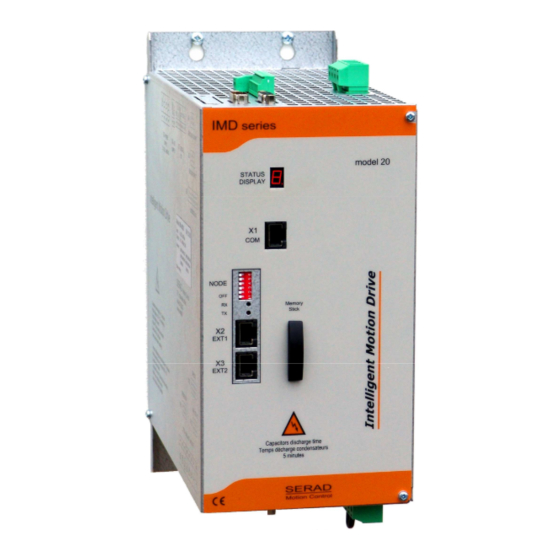
Page 8: 2-2- Front View
IMD 20 Drive installation guide 2-2- Front view STATUS 7-segment diagnostic display RS-232 serial port for communication with a PC EXT1 Extension: Optional communications ports EXT2 Extension: Optional communications ports R2101 - 8 - SERAD S.A... -
Page 9: 2-3- Top View
Multifunction encoder input 24Vdc Auxiliary 24V DC supply Digital I/O POWER SUPPLY Single / Three-phase power supply EXT I/O Option: I/O expansion board SAFE Option : Secure input The voltage on connector X8 can reach 480V! R2101 - 9 - SERAD S.A... -
Page 10: 2-4- Bottom View
Care must be taken when making connection to connector X10. An incorrect connection can seriously damage the drive. Dangerous voltages are present on X10 (900V). Wait at least 5 minutes to allow the capacitors to discharge before remove connector. R2101 - 10 - SERAD S.A... -
Page 11: 2-5- Mounting
Several drives can be mounted side-by-side provided that enough space (at least 20 mm) is left to ensure good natural convection. Let a space greater than 90 cm over and under drives to allow for the various connectors and cables to be fitted R2101 - 11 - SERAD S.A... -
Page 12: 2-6- Connector Pin Assignments
In the iDPL software, the RS232 communication is established when the icon in the bottom left side is in this fixed state : If the connection is not stable (state icon connected/disconnected), check if the cable and the USB-serial converter are certified by SERAD. Otherwise please contact our technical department. 8-CTS... - Page 13 (120 Ω In CANopen, do not use the Node ID n° 1 if you have a multi drive project. RS232 communication allows communication with only 1 device (ex: 1 PLC and 1 IMD drive). R2101 - 13 - SERAD S.A...
- Page 14 IMD 20 Drive installation guide • Node Address : For RS422, RS485 and CANopen, the NodeID corresponds to the six firstly dipswitchs + 1 R2101 - 14 - SERAD S.A...
- Page 15 Channel A Channel A inverted Channel B Channel B inverted Channel Z Channel Z inverted SHIELD Connect the shield to the shell of the connector NC (Not connected): It is forbidden to connect this pins. R2101 - 15 - SERAD S.A...
- Page 16 NC (Not connected): It is forbidden to connect this pins. X6: 24V dc supply Connector: Removable 2 ways, 5.08mm pitch N° Nam e Type Description XGND 24Vdc Control card s upply, backup m otor pos ition R2101 - 16 - SERAD S.A...
- Page 17 Wait at least 5 minutes to allow the capacitors to discharge before remove connector. The armoured motor cable must arrive directly on the terminals of the drive. Connect the shield (on drive side) to the srew provided (see Front view of the drive). R2101 - 17 - SERAD S.A...
- Page 18 Output 10, programmable 0V digital I/O IOGND* 0V digital I/O IOGND* Connect the shield to the shell of the connector SHIELD * Pins 7, 24, 25: internal connection ** Pins 12, 13: internal connection R2101 - 18 - SERAD S.A...
- Page 19 Connect the external resistor between terminals 2 and 3 Care must be taken when making connection to connector X10. An incorrect connection can seriously damage the drive. Dangerous voltages are present on X10. SERAD MOTOR DESCRIPTION Phase U Phase V...
- Page 20 7 COS - 5 REF + 9 REF - 6 TEMP + 2 TEMP - SHIELD Shield clamp Resolver connector Shield reverss SUB-D 9 way male around the ring Metallic casing Resolver connector M23 Cable clamp R2101 - 20 - SERAD S.A...
- Page 21 Motor temperature sensor Lo +8,3V +8.3V, 150 mA output(HIPERFACE) DATA DATA (EnDat*) RS485 (HIPERFACE) CLOCK (EndDat*) Cosine Lo Sine Lo SHIELD Connect the shield to the shell of the connector * EnDat in develloping R2101 - 21 - SERAD S.A...
- Page 22 IMD 20 Drive installation guide X SAFE : Option : Secure input SIL2 Connector removable 2 ways, 3.81mm pitch N° Name Type Description Input Refer to the documentation Safety option installation guide available on www.serad.fr R2101 - 22 - SERAD S.A...
-
Page 23: 2-7- Cables
(ex. Motion controller …) • Motor feedback cable (resolver), X11: Screened cable with 4 twisted pairs, 0.25 mm² Ground the shield of the feedback SUBD as shown below: R2101 - 23 - SERAD S.A... -
Page 24: 2-8- Connection Diagrams / Protections
(obligatory on brake) and relay using RC elements or diodes( ex 1N4007). Maximal input Safety device: Wire Drive Input voltage current cutout C curve IMD / 20 400V triphasé 32,2A 25A maxi 4² Caution: the ringing current can reach 25A during 10ms. R2101 - 24 - SERAD S.A... -
Page 25: 2-9- Stand-Alone Drive
IMD 20 Drive installation guide 2-9- Stand-alone drive The output Q2 is NPN open collector, 100mA max. The load must be connected between Q2 and +24Vdc. R2101 - 25 - SERAD S.A... -
Page 26: 2-10- Drive Controlled By A Motion Controller
IMD 20 Drive installation guide 2-10- Drive controlled by a motion controller The output Q2 is NPN open collector, 100mA max. The load must be connected between Q2 and +24Vdc. R2101 - 26 - SERAD S.A... -
Page 27: 2-11- Connecting A Motor Brake
With the Enable input off, switch on the auxiliary 24V dc supply. Ensure that on the STATUS display, the point blinking. Apply power. If the Status display shows an error message check the list of error codes. R2101 - 27 - SERAD S.A... -
Page 28: 2-13- Status Display
2) OS initialisation The segments switch on fastly in the following order : → → → → 3) End initialisation, the number of OS version is displayed The example above gives you the OS version 3.38 R2101 - 28 - SERAD S.A... - Page 29 If the instructions display is used in a tasks, the display is a priority. • Motor position state The segments around are moving serving the motor position. Rotation Rotation moving + moving - If the instructions display is used in a tasks, the display is a priority. R2101 - 29 - SERAD S.A...
- Page 30 If a problem occurs during the loading of the Operating System, the drive remains blocked and the STATUS DISPLAY displays a fixed In this case, turn off / on the drive and then load the Operating System again. R2101 - 30 - SERAD S.A...
-
Page 31: 2-14- Error Messages
(division by zero, not correct instruction, CAM or synchro. movement error …). Following error : the maximum following error has been exceeded.Contact technical support. FLASH memory error: impossible writting. Contact technical support. R2101 - 31 - SERAD S.A... - Page 32 The loading from the memory stick to the drive have failed, because the datas are corrupted. The memory stick have been remove and update by the drive project. External communication failed. The EtherCAT communication lost. R2101 - 32 - SERAD S.A...
Need help?
Do you have a question about the IMD 20 Series and is the answer not in the manual?
Questions and answers