
Related Manuals for SERAD IMD / 1


Summary of Contents for SERAD IMD / 1
- Page 1 Digital DRIVE for Brushless motor IMD Series INSTALLATION GUIDE Read manual before installing and respect all indications with this icon: IMD-GI/EN...
-
Page 3: Table Of Contents
2-8- Connection diagrams / Protections ............22 2-9- Stand-alone drive ..................22 2-10- Drive controlled by a motion controller ..........24 2-11- Connecting a motor brake..............25 2-12- System checks before starting ..............25 2-13- Error messages: ..................26 R722 - 3 - SERAD S.A... -
Page 4: 1- Introduction
We have gone to great lengths to ensure this documentation is correct and complete. However, since it is not possible to produce an absolutely error-free text. No responsibility will be assumed by SERAD for all damages caused by using this documentation and software. -
Page 5: 1-2- Md Series Drive Description
Input impedance : 20 Kohms Resolution : 16 bits for input 1 and 12 bits for input 2 1 output : Output voltage : ±10 V Analogue output : Maximum current : 5 mA Resolution : 8 bits R722 - 5 - SERAD S.A... - Page 6 Weight 3,6 Kg Drive Rated current Peak current ( 2s ) Rated power Dimensions w x h x d IMD / 1 1,25 Aeff 2,5 Aeff 0,7 kVA 72 x 293 x 233 IMD / 2 2,5 Aeff 5 Aeff...
-
Page 7: 2- Installation
On detection of an excess following error the drive will be put in open loop mode and the drive ready relay will be opened. If another action is required you should use the SECURITY instruction. R722 - 7 - SERAD S.A... -
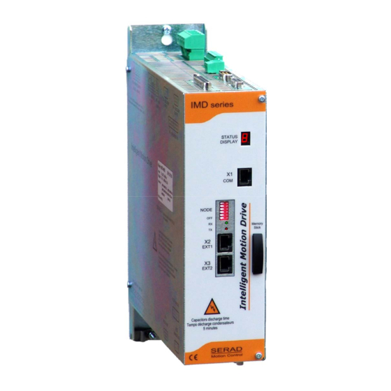
Page 8: 2-2- Front View
EXT1 EXT2 Ø6 Raccordement de la tresse de blindage du câble moteur STATUS 7-segment diagnostic display RS-232 serial port for communication with a PC EXT1 Extension: Optional communications ports EXT2 Extension: Optional communications ports R722 - 8 - SERAD S.A... -
Page 9: 2-3- Top View
Multifunction encoder output ENCODER INPUT Multifunction encoder input 24Vdc Auxiliary 24V DC supply Digital I/O POWER SUPPLY Single / Three-phase power supply EXT I/O Option: I/O expansion board The voltage on connector X8 can reach 480V! R722 - 9 - SERAD S.A... -
Page 10: 2-4- Bottom View
Care must be taken when making connection to connector X10. An incorrect connection can seriously damage the drive. Dangerous voltages are present on X10 (900V). Wait at least 5 minutes to allow the capacitors to discharge before remove connector. R722 - 10 - SERAD S.A... -
Page 11: 2-5- Mounting
X 10 - BA LLA ST / M O TO R X 11 RE S O LVER ANALO G I/O RA CC O R DE M ENT B LINDAG E M O TE UR R722 - 11 - SERAD S.A... -
Page 12: 2-6- Connector Pin Assignments
X1: RJ45 serial port for downloading programs and parameters. N° Nam e Type Description Receive data Trans m it data Clear to s end SHIELD Connect the s hield to the s hell of the connector 8-CTS 5-GND 3-TXD 2-RXD R722 - 12 - SERAD S.A... - Page 13 Dipswitchs value = 1 + 4 = 5 NodeID = 5 + 1 = 6 • Put on Dipswitch 6 to activate terminal resistor (120Ω). RS232 communication allows communication with only 1 device (ex: 1 PLC and 1 IMD drive). R722 - 13 - SERAD S.A...
- Page 14 Channel A inverted /Data Channel B Clock Channel B inverted /Clock Zero marker Zero marker inverted SHIELD Connect the shield to the shell of the connector NC (Not connected): It is forbidden to connect this pins. R722 - 14 - SERAD S.A...
- Page 15 NC (Not connected): It is forbidden to connect this pins. 24V dc supply Connector: Removable 2 ways, 5.08mm pitch N° Nam e Type Description XGND 24Vdc Control card s upply, backup m otor pos ition R722 - 15 - SERAD S.A...
- Page 16 Wait at least 5 minutes to allow the capacitors to discharge before remove connector. The armoured motor cable must arrive directly on the terminals of the drive. Connect the shield (on drive side) to the srew provided (see Front view of the drive). R722 - 16 - SERAD S.A...
- Page 17 0V digital I/O IOGND* 0V digital I/O IOGND* Conne ct the shie ld to the she ll of the conne ctor SHIELD * Pins 7, 24, 25: internal connection ** Pins 12, 13: internal connection R722 - 17 - SERAD S.A...
- Page 18 Connect the external resistor between terminals 2 and 3 Care must be taken when making connection to connector X10. An incorrect connection can seriously damage the drive. Dangerous voltages are present on X10. SERAD MOTOR DESCRIPTION Phase U Phase V...
- Page 19 7 COS - 5 REF + 9 REF - 6 TEMP + 2 TEMP - SHIELD Shield clamp Resolver connector Shield reverss SUB-D 9 way male around the ring Metallic casing Resolver connector M23 Cable clamp R722 - 19 - SERAD S.A...
- Page 20 +8,3V +8.3V, 150 mA output(HIPERFACE) DATA DATA (EnDat*) RS485 (HIPERFACE) CLOCK (EndDat*) Cosine Lo Sine Lo SHIELD Conne ct the shie ld to the she ll of the conne ctor * EnDat in develloping R722 - 20 - SERAD S.A...
- Page 21 (ex. Motion controller …) • Motor feedback cable (resolver), X11: Screened cable with 4 twisted pairs, 0.25 mm² Ground the shield of the feedback SUBD as shown below: R722 - 21 - SERAD S.A...
-
Page 22: 2-8- Connection Diagrams / Protections
(obligatory on brake) and relay using RC elements or diodes( ex 1N4007). Safety device : cutout C curcve Drive Input voltage Maximal input current Wire IMD / 1 400V triphased 2,2A 20A maxi 1,5² 230V monophased 3,5A 20A maxi 1,5²... -
Page 23: 2-9- Stand-Alone Drive
IMD Drive installation guide 2-9- Stand-alone drive The output Q2 is NPN open collector, 100mA max. The load must be connected between Q2 and +24Vdc. R722 - 23 - SERAD S.A... -
Page 24: 2-10- Drive Controlled By A Motion Controller
IMD Drive installation guide 2-10- Drive controlled by a motion controller The output Q2 is NPN open collector, 100mA max. The load must be connected between Q2 and +24Vdc. R722 - 24 - SERAD S.A... -
Page 25: 2-11- Connecting A Motor Brake
With the Enable input off, switch on the auxiliary 24V dc supply. Ensure that the STATUS display is lit. Apply power. If the Status display shows an error message check the list of error codes. R722 - 25 - SERAD S.A... -
Page 26: 2-13- Error Messages
(division by zero, not correct instruction, CAM or synchro. movement error …). Following error : the maximum following error has been exceeded.Contact technical support. FLASH memory error: impossible writting. Contact technical support. R722 - 26 - SERAD S.A... - Page 27 FPGA error : impossible loading or CAN communication error. Contact technical support. Over velocity : motor velocity is highter than nominal speed in torque mode Feedback saturation error. Feedback or SinCos signals are too high. R722 - 27 - SERAD S.A...
Need help?
Do you have a question about the IMD / 1 and is the answer not in the manual?
Questions and answers