Table of Contents
Advertisement
Quick Links
INSTRUCTION MANUAL
HI2004-18 • HI2004-28
HI2014-18 • HI2014-28
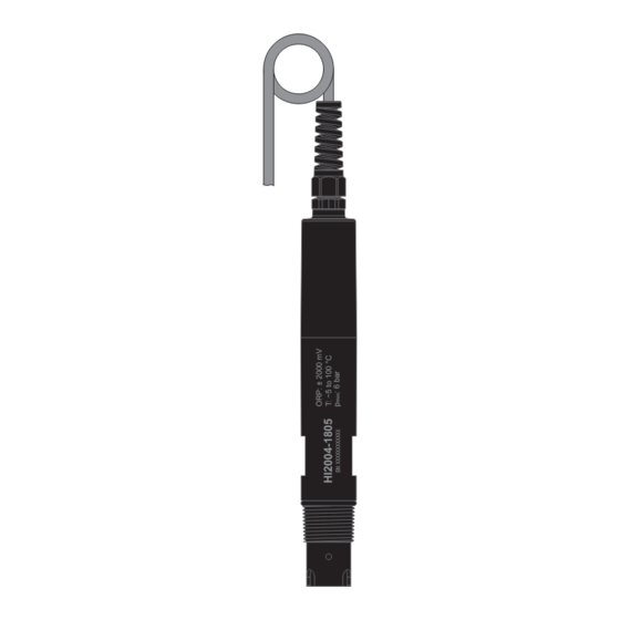
ORP and Temperature
Industrial Smart Probes
HI510 Compatible
®
Hanna
is committed to developing and deploying digital solutions
with a positive impact on the environment and climate.
Please scan the QR code or follow the link
to download the
HI510
https://manuals.hannainst.com/HI510
Hanna Instruments Inc., 584 Park East Drive, Woonsocket, RI 02895 USA
controller user manual.
www.hannainst.com
Advertisement
Table of Contents

Subscribe to Our Youtube Channel
Related Manuals for Hanna Instruments HI2004-18


Summary of Contents for Hanna Instruments HI2004-18
- Page 1 Please scan the QR code or follow the link to download the HI510 controller user manual. https://manuals.hannainst.com/HI510 Hanna Instruments Inc., 584 Park East Drive, Woonsocket, RI 02895 USA www.hannainst.com...
-
Page 2: Table Of Contents
All rights are reserved. Reproduction in whole or in part is prohibited without the written consent of the copyright owner, Hanna Instruments Inc., Woonsocket, Rhode Island, 02895, USA. Hanna Instruments reserves the right to modify the design, construction, or appearance of its products without advance notice. -
Page 3: Preliminary Examination
3. GENERAL DESCRIPTION & INTENDED USE ® HI20X4-18 HI20X4-28 are ORP and temperature probes designed for use with the Hanna Instruments HI510 Universal Process Controller. The system is designed to monitor and control disinfection chemicals or follow and control a critical oxidation (or reduction) reaction. -
Page 4: Main Features
Main Features 4. MAIN FEATURES • Rugged, chemically-resistant PVDF body • 3/4” NPT external thread • 6 bar (87 psi) maximum pressure at 25 °C (77 °F) • Built-in temperature sensor for measurement • Digital probe stores model, firmware, serial number, and calibration information •... -
Page 5: Specifications
5 Specifications 6. SPECIFICATIONS HI2004-18zz Range –2000 to +2000 mV Resolution 1 mV Accuracy ± 2 mV Calibration Single point, value can be adjusted ±60 mV around measured mV Range –5.0 to 100.0 °C (23.0 to 212.0 °F) Resolution 0.1 °C; 0.1 °F Temperature Accuracy ±... -
Page 6: Probe Dimensions & Cable Connection
Probe Dimensions & Cable Connection 7. PROBE DIMENSIONS & CABLE CONNECTION Ø 22 mm (0.9”) Ø 28 mm (1.1”) 3/4’’ NPT 21 mm (0.8") 43 mm (1.7") 185 mm (7.3”) 187 mm (7.4”) Align the pins and key then push the plug into the socket. Rotate the collar to lock in place. - Page 7 Installation Typical installation examples with mounting accessories Accessories are sold separately. In-line mounting and flow-cell installation require that the saddle and flow cell are completely filled with water. In-line mounting with probe saddle 1 Probe 2 Probe fitting kit 3 Saddle 4 Sensor tip 5 Pipe Note: Probe can be rotated to prevent air entrapment inside the electrode.
- Page 8 Installation Tank immersion with submersible electrode holder 1 Probe cable 2 Cable gland 3 Electrode holder cap 4 Adjustable immersion level 5 Electrode holder 6 Probe body 7 O-ring, Ø 22.2 mm (0.87”) 8 Sensor tip 9 Protective end cap HI60501 HI60503 (PVC / PVDF submersible holders) and...
- Page 9 Installation Flow-cell installation Do not allow deposits of sediment or other foreign material to accumulate within the sensing area. 1 Process controller FLOW CELL 2 Wiring cable 3 ORP probe 4 Flow-cell adapter EXIT FLOW 5 Flow cell 6 Flow-cell valves 7 Saddle VALVE 2 VALVE 1...
-
Page 10: Wiring The Probe To The Controller
Wiring the Probe to the Controller 9. WIRING THE PROBE TO THE CONTROLLER 1. With the controller disconnected from power, run the probe cable through the conduit opening. 2. Connect the probe leads to the removable terminal connector marked PROBE. Follow the lead markings (+) positive / (–) negative to ensure correct wiring position for the output leads. -
Page 11: Maintenance & Conditioning
Maintenance & Conditioning • Do not let the probe touch the bottom or sides of the container. • Remove the air bubbles from under the probe tip. Stir the sample at a slow to moderate rate and wait a few seconds for the reading to stabilize. Note: ORP calibration standards may be used with the probe directly i.e. -
Page 12: Accessories
Accessories In case of errors or faulty/fluctuating readings, gently polish the metal tip with a lightly abrasive paper, paying attention not to scratch the surface. Follow with a thorough wash with water. Storage • When the probe is removed from the process for more than 1 hour, fill the protective cap with HI70300 Storage solution and tighten the cap on the sensor. -
Page 13: Abbreviations
Abbreviations Ordering Information Product Description BL120-402 Flow-cell tubing,10 m (32’9”) BL120-410 Flow cell BL120-450 Flow-cell kit for Ø 50 mm (2”) pipe BL120-463 Flow-cell kit for Ø 63 mm (2.5”) pipe BL120-475 Flow-cell kit for Ø 75 mm (3”) pipe BL120-500 Probe fitting kit BL120-550... -
Page 14: Certification
If the repair is not covered by the warranty, you will be notified of the charges incurred. If the instrument is to be returned to Hanna Instruments, first obtain a Returned Goods Authorization (RGA) number from the Technical Service department and then send it with shipping costs prepaid.
Need help?
Do you have a question about the HI2004-18 and is the answer not in the manual?
Questions and answers