Table of Contents
Advertisement
Quick Links
UNVENTED (VENT-FREE) GAS LOG HEATER
OWNER'S OPERATION AND INSTALLATION MANUAL
Remote-Ready Models VUL18/24/30/36(N,P)R
Thermostatically-Controlled Models VUL18/24/30/36(N,P)T
Remote-Ready Models Also Design-Certified As Vented Decorative Appliances
WARNING: If the information in this manual is not
followed exactly, a fire or explosion may result causing
property damage, personal injury or loss of life.
— Do not store or use gasoline or other flammable
vapors and liquids in the vicinity of this or any other
appliance.
— WHAT TO DO IF YOU SMELL GAS
• Do not try to light any appliance.
• Do not touch any electrical switch; do not use any
phone in your building.
• Immediately call your gas supplier from a neighbor's
phone. Follow the gas supplier's instructions.
• If you cannot reach your gas supplier, call the fire
department.
— Installation and service must be performed by a quali-
fied installer, service agency or the gas supplier.
INSTALLER: Leave this manual with the appliance.
CONSUMER: Retain this manual for future reference.
Vantage
For more information, visit www.fmiproducts.com
Hearth
TM
by FMI PRODUCTS, LLC
PFS
®
US
Advertisement
Table of Contents

Related Manuals for FMI VUL18


Summary of Contents for FMI VUL18
- Page 1 Vantage Hearth by FMI PRODUCTS, LLC UNVENTED (VENT-FREE) GAS LOG HEATER OWNER’S OPERATION AND INSTALLATION MANUAL ® Remote-Ready Models VUL18/24/30/36(N,P)R Thermostatically-Controlled Models VUL18/24/30/36(N,P)T Remote-Ready Models Also Design-Certified As Vented Decorative Appliances WARNING: If the information in this manual is not followed exactly, a fire or explosion may result causing property damage, personal injury or loss of life.
-
Page 2: Table Of Contents
TAbLE OF CONTENTS Safety ..............2 Wiring Diagram ..........26 Unpacking............5 Troubleshooting ..........27 Product Identification ........... 5 Optional Positioning of Local Codes............5 Thermostat Sensing Bulb ......31 Optional Remote Control Accessories ....5 Specifications ............ 31 Product Features ..........6 Parts .............. - Page 3 SAFETy Continued WARNING: This product con- WARNING: Do not allow fans tains and/or generates chemicals to blow directly into the fireplace. known to the state of California Avoid any drafts that alter burner to cause cancer or birth defects flame patterns. Ceiling fans can or other reproductive harm.
- Page 4 SAFETy Continued 1. This appliance is only for use with the type 9. Before using furniture polish, wax, carpet of gas indicated on the rating plate. This cleaner or similar products, turn heater off. If appliance is not convertible for use with heated, the vapors from these products may other gases.
-
Page 5: Unpacking
3. Check heater for any shipping damage. If information. heater is damaged call FMI PRODUCTS, LLC at 1-866-328-4537 for replacement 1. Remove logs and heater base assembly parts before returning to dealer. -
Page 6: Product Features
PRODUCT FEATURES OPERATION SAFETY DEVICE This heater is clean burning. It requires no This heater has a pilot with an Oxygen Deple- outside venting. There is no heat loss out a tion Sensing (ODS) safety shutoff system. The vent or up a chimney. Heat is generated by ODS/pilot is a required feature for vent-free both realistic flames and glowing coals. - Page 7 AIR FOR COMbUSTION AND VENTILATION Continued If your home meets all of the three criteria 2. Multiply the space volume by 20 to determine the maximum Btu/Hr the space can support. above, you must provide additional fresh air. See Ventilation Air From Outdoors, ________ (volume of space) x 20 = (Maxi- page 8.
- Page 8 AIR FOR COMbUSTION AND VENTILATION Continued Ventilation Air From Outdoors WARNING: If the area in which Provide extra fresh air by using ventilation the heater may be operated does grills or ducts. You must provide two perma- nent openings: one within 12" of the ceiling not meet the required volume for and one within 12"...
-
Page 9: Installation
INSTALLATION NOTICE: This heater is intended WARNING: Seal any fresh for use as supplemental heat. air vents or ash clean-out doors Use this heater along with your located on floor or wall of fire- primary heating system. Do not place. If not, drafting may cause install this heater as your pri- pilot outage or sooting. - Page 10 INSTALLATION Continued CHECK GAS TYPE Example: The face of a mantel, bookshelf, etc. is made of combustible material and Use the correct type of gas (natural or propane/ protrudes 3 " from the wall. This com- LP). If your gas supply is not the correct gas bustible material must be 4"...
- Page 11 INSTALLATION Continued MINIMUM NONCOMbUSTIbLE If Using Mantel MATERIAL CLEARANCES You must have noncombustible material(s) above the fireplace opening. Noncombustible If Not Using Mantel materials (such as slate, marble, tile, etc.) Note: If using a mantel proceed to If Using must be at least 1/2" thick. With sheet metal, Mantel.
- Page 12 INSTALLATION Continued Determining Minimum Mantel Clearance FLOOR CLEARANCES When Using a Hood A. If installing appliance on the floor level, If minimum clearances in Figure 6, page 11, are you must maintain the minimum distance not met, you must have a hood. When using of 14"...
- Page 13 INSTALLATION Continued 2. State or local codes do not permit vent- INSTALLING HEATER bASE free operation. ASSEMbLY 3. You prefer vented operation. WARNING: You must secure If reasons number 1 or 2 apply to you, you must permanently open chimney flue damper. this heater to fireplace floor.
- Page 14 INSTALLATION Continued Masonry 1. Apply pipe joint sealant lightly to male Screw threads of gas fitting (provided). For Thermostatically-Controlled Models con- nect approved flexible gas hose to gas regulator of heater (see Figure 11). For Remote-Ready models connect approved flexible gas hose to inlet side of gas con- trol (see Figure 12).
- Page 15 INSTALLATION Continued Installation Items Needed IMPORTANT: Install equipment shutoff valve Before installing heater, make sure you have in an accessible location. The equipment the items listed below. shutoff valve is for turning on or shutting off the gas to the appliance. •...
- Page 16 INSTALLATION Continued We recommend that you install a sediment CHECKING GAS CONNECTIONS trap in supply line as shown in Figure 15, WARNING: Test all gas piping page 15, or Figure 16, depending on your model. Locate sediment trap where it is within and connections, internal and reach for cleaning.
- Page 17 INSTALLATION Continued Test Pressures Equal To or Less Than PRESSURE TESTING HEATER GAS 1/2 PSIG (3.5 kPa) CONNECTIONS 1. Close equipment shutoff valve (see Fig- 1. Open equipment shutoff valve (see Fig- ure 17). ure 17). 2. Pressurize supply piping system by either 2.
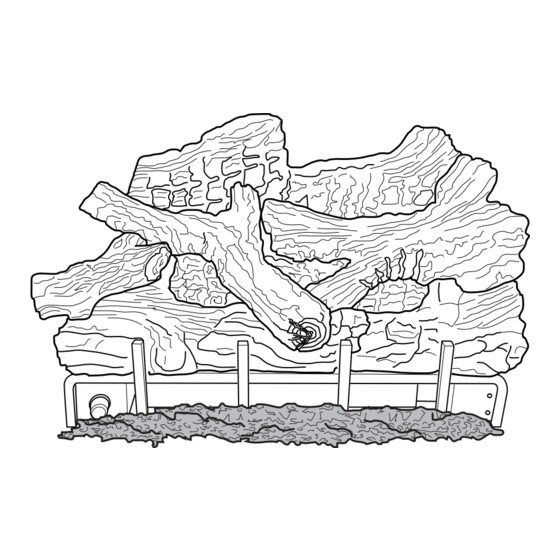
- Page 18 INSTALLATION Continued INSTALLING LOGS Installing Logs (All Models) 1. Place bottom log in center of the base as- WARNING: Failure to posi- sembly as shown in Figure 21. tion the parts in accordance 2. Rest rear log in back corner sections of base assembly as shown in Figure 21.
-
Page 19: Operation
Right Small Front Log Figure 23 - Installing VUL36 Model Control Cover Logs Pin on Front Bottom Left Log VUL18/24/30 MODELS Figure 22 - Installing Log Sets VUL36 MODELS Figure 24 - Correct Log Placement OPERATION THERMOSTAT-CONTROLLED MODELS FOR YOUR SAFETY B. - Page 20 OPERATION Continued THERMOSTAT-CONTROLLED MODELS C. Use only your hand to push in or turn WARNING: Damper handle the gas control knob. Never use tools. will be hot if heater has been If the knob will not push in or turn by running.
- Page 21 OPERATION Continued THERMOSTAT-CONTROLLED MODELS Note: If pilot goes out, repeat steps 3 2. Close equipment shutoff valve (see Figure through 7. This heater has a safety inter- 17, page 17). lock system. Wait one (1) minute for sys- THERMOSTAT CONTROL tem to reset before lighting pilot again.
- Page 22 OPERATION Continued REMOTE-READy MODELS LIGHTING WARNING: burners will come INSTRUCTIONS on automatically within one minute when the selector switch is in the WARNING: ON position after the pilot is lit. • If fireplace has glass doors, never operate this heater with 5.
- Page 23 OPERATION Continued REMOTE-READy MODELS 10. Wait one minute and switch selector TO TURN OFF GAS switch to the ON position to light burners. TO APPLIANCE Note: AUTO is only functional when using 1. Turn control knob clockwise to the GWMT1 or GWMS2 optional accessories. OFF position.
-
Page 24: Inspecting Burners
INSPECTING bURNERS Check pilot flame pattern and burner flame WARNING: If yellow tipping patterns often. occurs, your heater could pro- PILOT FLAME PATTERN duce increased levels of carbon Figure 30 shows a correct pilot flame pattern. monoxide. If front burner flame Figure 31 shows an incorrect pilot flame pat- pattern shows yellow tipping, tern. -
Page 25: Cleaning And Maintenance
CLEANING AND MAINTENANCE every three months during operation and WARNING: Turn off heater have heater inspected yearly by a qualified and let cool before cleaning. service person. We also recommend that you keep the burner tube and pilot assembly clean and free of dust CAUTION: You must keep and dirt. -
Page 26: Wiring Diagram
CLEANING AND MAINTENANCE Continued 4. Check injector holder located at the end of LOGS the burner tube again. Remove any large • If you remove logs for cleaning, refer to particles of dust, dirt, lint or pet hair with Installing Logs, page 19, to properly replace a soft cloth or vacuum cleaner nozzle. -
Page 27: Troubleshooting
TROUbLESHOOTING WARNING: Turn off heater and let cool before servicing. Only a qualified service person should service and repair heater. CAUTION: Never use a wire, needle or similar object to clean ODS/pilot. This can damage ODS/pilot unit. Note: All troubleshooting items are listed in order of operation. ObSERVED PRObLEM POSSIbLE CAUSE REMEDY... - Page 28 TROUbLESHOOTING Continued ObSERVED PRObLEM POSSIbLE CAUSE REMEDY ODS/pilot lights but flame 1. Control knob not fully 1. Press in control knob fully goes out when control knob pressed in is released 2. Control knob not pressed in 2. After ODS/pilot lights, keep long enough control knob pressed in 30 seconds...
- Page 29 TROUbLESHOOTING Continued ObSERVED PRObLEM POSSIbLE CAUSE REMEDY Yellow flame in front burner 1. Not enough air 1. Check burner(s) for dirt during burner combustion and debris. If found, clean burner(s) (see Cleaning and Maintenance, page 25) 2. Gas regulator defective 2.
- Page 30 TROUbLESHOOTING Continued WARNING: If you smell gas • Shut off gas supply. • Do not try to light any appliance. • Do not touch any electrical switch; do not use any phone in your building. • Immediately call your gas supplier from a neighbor’s phone. Fol- low the gas supplier’s instructions.
-
Page 31: Optional Positioning Of
OPTIONAL POSITIONING OF THERMOSTAT SENSING bULb (Thermostat-Controlled Models Only) 3. The thermostat sensing bulb may be located to the lower right front side of FOR MASONRY AND FACTORY- fireplace. Place bulb in an area that will bUILT METAL FIREPLACE be close to room temperature when log If your log set cycles to pilot, but the room set is operating. -
Page 32: Parts
PARTS THERMOSTAT-CONTROLLED MODELS VUL18NT, VUL18PT, VUL24NT, VUL24PT, VUL30NT, VUL30PT, VUL36NT, VUL36PT www.fmiproducts.com 122001-01E... - Page 33 PARTS THERMOSTAT-CONTROLLED MODELS This list contains replaceable parts used in your heater. When ordering parts, follow the instructions listed under Replacement Parts on page 38 of this manual. NO. PART NO. DESCRIPTION QTY. Ramp Burner Base • • • • •...
- Page 34 PARTS REMOTE-READY VARIAbLE CONTROL MODELS VUL18NR, VUL18PR, VUL24NR, VUL24PR, VUL30NR, VUL30PR, VUL36NR, VUL36PR www.fmiproducts.com 122001-01E...
- Page 35 PARTS REMOTE-READY VARIAbLE CONTROL MODELS This list contains replaceable parts used in your heater. When ordering parts, follow the instructions listed under Replacement Parts on page 38 of this manual. NO. PART NO. DESCRIPTION QTY. Ramp Burner Base • • •...
- Page 36 PARTS LOG MODELS VUL18NT, VUL18PT, VUL24NT, VUL24PT, VUL30NT, VUL30PT, VUL18NR, VUL18PR, VUL24NR, VUL24PR, VUL30NR, VUL30PR This list contains replaceable parts used in your heater. When ordering parts, follow the instructions listed under Replacement Parts on page 38 of this manual. PART NUMbER VUL18NT VUL24NT...
- Page 37 PARTS LOG MODELS VUL36NR, VUL36PR, VUL36NT AND VUL36PT This list contains replaceable parts used in your heater. When ordering parts, follow the instructions listed under Replacement Parts on page 38 of this manual. PART NUMbER VUL36NT VUL36NR VUL36PT VUL36PR DESCRIPTION 121699-07 121699-13 Bottom Log 121699-14 121699-14 Middle Right Log 121699-15 121699-15 Middle Left Log...
-
Page 38: Service Hints
• propane/LP gas supply may be low serial numbers of your heater ready. You may feel your gas pressure is too low. If You can also visit FMI PRODUCTS, LLC’s so, contact your local propane/LP or natural technical services web site at gas supplier. - Page 39 ACCESSORIES Continued WALL-MOUNT ON/OFF SWITCH GWMS2 For all Remote-Ready Models. Allows the gas log heater to be turned on and off with a wall switch. MODE VENT-FREE LOGMATE FIREbOXES ® Available in 32", 36" and 42" models. Circulating fireboxes feature louvers and an optional blower.
-
Page 40: Warranty
This is FMI PRODUCTS, LLC’s exclusive warranty, and to the full extent allowed by law; this express war- ranty excludes any and all other warranties, express or implied, written or verbal and limits the duration of...
Need help?
Do you have a question about the VUL18 and is the answer not in the manual?
Questions and answers