Table of Contents
Advertisement
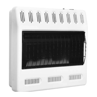
UNVENTED (VENT-FREE) BLUE FLAME GAS HEATER
SAFETY INFORMATION AND INSTALLATION MANUAL
WARNING: If the information in this manual is not
followed exactly, a fire or explosion may result causing
property damage, personal injury or loss of life.
— Do not store or use gasoline or other flammable
vapors and liquids in the vicinity of this or any other
appliance.
— WHAT TO DO IF YOU SMELL GAS
• Do not try to light any appliance.
• Do not touch any electrical switch; do not use any
phone in your building.
• Immediately call your gas supplier from a neighbor's
phone. Follow the gas supplier's instructions.
• If you cannot reach your gas supplier, call the fire
department.
— Installation and service must be performed by a quali-
fied installer, service agency or the gas supplier.
INSTALLER: Leave this manual with the appliance.
CONSUMER: Retain this manual for future reference.
For more information, visit www.fmiproducts.com
MODELS
GWN20TC, GWP20TC,
GWN30TC, GWP30TC,
VSHN20T, VSHP20T,
VSHN30T, VSHP30T
PFS
®
US
Advertisement
Table of Contents

Related Manuals for FMI GWN20TC


Summary of Contents for FMI GWN20TC
- Page 1 UNVENTED (VENT-FREE) BLUE FLAME GAS HEATER SAFETY INFORMATION AND INSTALLATION MANUAL ® MODELS GWN20TC, GWP20TC, GWN30TC, GWP30TC, VSHN20T, VSHP20T, VSHN30T, VSHP30T WARNING: If the information in this manual is not followed exactly, a fire or explosion may result causing property damage, personal injury or loss of life.
-
Page 2: Table Of Contents
TABLE OF CONTENTS Safety ..............2 Cleaning and Maintenance ........ 18 Local Codes............4 Troubleshooting ..........19 Product Identification ........... 4 Specifications ............ 23 Unpacking............4 Replacement Parts ..........23 Product Features ..........4 Service Hints ............. 23 Air For Combustion and Ventilation ..... 5 Technical Service.......... - Page 3 SAFETY Continued Natural and Propane/LP Gas: Natural and Keep the appliance area clear propane/LP gases are odorless. An odor- and free from combustible ma- making agent is added to these gases. The terials, gasoline and other flam- odor helps you detect a gas leak. However, the mable vapors and liquids.
-
Page 4: Local Codes
Heater to heater for shipment. Ignitor Button Cabinet 3. Check heater for any shipping damage. If heater is damaged call FMI PRODUCTS, LLC at 1-866-328-4537 for replacement parts before returning to dealer. PRODUCT FEATURES SAFETY DEvICE This heater has a pilot with an Oxygen Deple- tion Sensing (ODS) safety shutoff system. -
Page 5: Air For Combustion And Ventilation
AIR FOR COMBUSTION AND VENTILATION Unusually Tight Construction WARNING: This heater shall The air that leaks around doors and windows not be installed in a room or space may provide enough fresh air for combustion and ventilation. However, in buildings of un- unless the required volume of in- usually tight construction, you must provide door combustion air is provided... - Page 6 AIR FOR COMBUSTION AND VENTILATION Continued DETERMINING FRESH-AIR FLOW 4. Compare the maximum Btu/Hr the space can support with the actual amount of Btu/ FOR HEATER LOCATION Hr used. Determining if You Have a Confined or _______ Btu/Hr (maximum can support) Unconfined Space _______ Btu/Hr (actual amount used) Use this work sheet to determine if you have...
-
Page 7: Installation
AIR FOR COMBUSTION AND VENTILATION Continued vENTILATION AIR Ventilation Air From Inside Building 12" This fresh air would come from an adjoining unconfined space. When ventilating to an adjoining unconfined space, you must provide Ventilation Grills two permanent openings: one within 12" (30.5 Into Adjoining Room, Ventilation Option 2... - Page 8 INSTALLATION Continued INSTALLATION ITEMS CAUTION: This heater creates Before installing heater, make sure you have warm air currents. These currents the items listed below. move heat to wall surfaces next • for propane/LP gas, external regulator (supplied by installer) to heater. Installing heater next •...
- Page 9 INSTALLATION Continued Front Panel Screw CEILING 10" (25.4 cm) 36" Minimum (91.5 cm) From Minimum Sides Of Heater Right Side Left Side Minimum To Top Surface Of Carpeting, Tile Or Other 2" (5.1 cm) 36" Combustible (91.5 cm) Material FLOOR Figure 4 - Mounting Clearances As Figure 6 - Removing Front Panel of...
- Page 10 INSTALLATION Continued Attaching To Wall Anchor Method 2. Mark screw locations on wall (see Figure 7). For attaching mounting bracket to hollow Note: Only mark last hole on each end of walls (wall areas between studs) or solid walls mounting bracket. Insert mounting screws (concrete or masonry) through these holes only.
- Page 11 INSTALLATION Continued MOUNTING HEATER TO FLOOR Installing Bottom Mounting Screws WITH OPTIONAL FLOOR KIT 1. Locate two bottom mounting holes. These Mounting Base Feet to Heater holes are near bottom on back panel of Note: A 90° elbow is required for mounting heater (see Figure 11).
- Page 12 INSTALLATION Continued CONNECTING TO GAS SUPPLY Typical Inlet Pipe Diameters 16-18,000 Btu/hr models - 3/8" or greater WARNING: This appliance 26-30,000 Btu/hr models - 1/2" or greater requires a 3/8" NPT (National Installation must include equipment shutoff Pipe Thread) inlet connection to valve, union and plugged 1/8"...
- Page 13 INSTALLATION Continued CHECKING GAS CONNECTIONS IMPORTANT: Hold the pressure regulator with wrench when connecting it to gas pip- WARNING: Test all gas piping ing and/or fittings. Do not over tighten pipe connection to regulator. The regulator body and connections, internal and could be damaged.
- Page 14 INSTALLATION Continued Test Pressures Equal To or Less Than 1/2 PSIG (3.5 kPa) Thermostat Gas Valve 1. Close equipment shutoff valve (see Fig- ure 15). 2. Pressurize supply piping system by either opening propane/LP supply tank valve for propane/LP gas or opening main gas Meter valve located on or near gas meter for natural gas or using compressed air.
-
Page 15: Operation
OPERATION FOR YOUR SAFETY 6. Turn control knob counterclockwise READ BEFORE LIGHTING to the PILOT position. Press in control knob for five (5) seconds. WARNING: If you do not fol- 7. With control knob pressed in, push down low these instructions exactly, and release ignitor button. - Page 16 OPERATION Continued MANUAL LIGHTING CAUTION: Do not try to ad- PROCEDURE just heating levels by using the 1. Remove front panel (see Figure 6, page 9). equipment shutoff valve. 2. Follow steps 1 through 5 under Lighting Instructions, page 15. Thermocouple Ignitor Electrode 3.
-
Page 17: Inspecting Heater
OPERATION unit heats up, the blower will operate. A few min- utes after unit cycles off or is turned off, blower Continued will shut off. Blower will cycle on and off in this Extension Cord manner. Note: If you have a heater with a ther- Use extension cord if needed. -
Page 18: Cleaning And Maintenance
CLEANING AND MAINTENANCE We also recommend that you keep the burner WARNING: Turn off heater tube and pilot assembly clean and free of dust and dirt. To clean these parts we recommend and let cool before cleaning. using compressed air no greater than 30 PSI. Your local computer store, hardware store or CAUTION: You must keep home center may carry compressed air in a... -
Page 19: Troubleshooting
TROUBLESHOOTING WARNING: Turn off and unplug heater and let cool before servicing. Only a qualified service person should service and repair heater. CAUTION: Never use a wire, needle or similar object to clean ODS/pilot. This can damage ODS/pilot unit. Note: All troubleshooting items are listed in order of operation. OBSERvED PROBLEM POSSIBLE CAUSE REMEDY... - Page 20 TROUBLESHOOTING Continued OBSERvED PROBLEM POSSIBLE CAUSE REMEDY ODS/pilot lights but flame 1. Control knob not fully 1. Press in control knob fully goes out when control knob pressed in is released 2. Control knob not pressed in 2. After ODS/pilot lights, keep long enough control knob pressed in 30 seconds...
- Page 21 TROUBLESHOOTING Continued OBSERvED PROBLEM POSSIBLE CAUSE REMEDY Yellow flame during burner 1. Not enough air 1. Clean burner (see Cleaning combustion and Maintenance, page 18) or replace burner orifice 2. Gas Regulator defective 2. Replace damaged burner 3. Clogged or dirty burner 3.
- Page 22 TROUBLESHOOTING Continued WARNING: If you smell gas • Shut off gas supply. • Do not try to light any appliance. • Do not touch any electrical switch; do not use any phone in your building. • Immediately call your gas supplier from a neighbor’s phone. Fol- low the gas supplier’s instructions.
-
Page 23: Specifications
Contact authorized dealers of this product. • model and serial numbers of your heater If they can’t supply original replacement • how heater was malfunctioning part(s), call FMI PRODUCTS, LLC at • type of gas used (propane/LP or natural 1-866-328-4537. gas) •... -
Page 24: Parts
PARTS MODELS GWN20TC, GWP20TC, GWN30TC, GWP30TC, VSHN20T, VSHP20T, VSHN30T, VSHP30T www.fmiproducts.com 125325-01A... - Page 25 PARTS This list contains replaceable parts used in your heater. When ordering parts, follow the instructions listed under Replacement Parts on page 23 of this manual. GWP20TC GWN20TC GWP30TC GWN30TC PART NO. DESCRIPTION VSHP20T VSHN20T VSHP30T VSHN30T QTY. 097159-04 Piezo Ignitor •...
-
Page 26: Accessories
Purchase these heater accessories from your local dealer. If they can not supply these accessories, either contact your nearest Parts Central or call FMI PRODUCTS, LLC at 1-866-328-4537 for information. You can also write to the address listed on the back page of this manual. - Page 27 NOTES _____________________________________________________ ______________________________________________________ ______________________________________________________ ______________________________________________________ ______________________________________________________ ______________________________________________________ ______________________________________________________ ______________________________________________________ ______________________________________________________ ______________________________________________________ ______________________________________________________ ______________________________________________________ ______________________________________________________ _____________________________________________________ ______________________________________________________ ______________________________________________________ ______________________________________________________ ______________________________________________________ ______________________________________________________ ______________________________________________________ ______________________________________________________ ______________________________________________________ ______________________________________________________ ______________________________________________________ ______________________________________________________ ______________________________________________________ _____________________________________________________ ______________________________________________________ ______________________________________________________ ______________________________________________________ ______________________________________________________ ______________________________________________________ ______________________________________________________ ______________________________________________________ ______________________________________________________ www.fmiproducts.com 125325-01A...
-
Page 28: Warranty
FMI PRODUCTS, LLC’s liability is limited to the purchase price of the product, and FMI PRODUCTS, LLC shall not be liable for any other damages whatsoever under any circumstances including indirect, incidental, or consequential damages.
Need help?
Do you have a question about the GWN20TC and is the answer not in the manual?
Questions and answers