Table of Contents
Advertisement
Quick Links
SAFETY INFORMATION AND INSTALLATION MANUAL
WARNING: If the information in this manual is not
followed exactly, a fire or explosion may result causing
property damage, personal injury or loss of life.
— Do not store or use gasoline or other flammable
vapors and liquids in the vicinity of this or any other
appliance.
— WHAT TO DO IF YOU SMELL GAS
• Do not try to light any appliance.
• Do not touch any electrical switch; do not use any
phone in your building.
• Immediately call your gas supplier from a neighbor's
phone. Follow the gas supplier's instructions.
• If you cannot reach your gas supplier, call the fire
department.
— Installation and service must be performed by a quali-
fied installer, service agency or the gas supplier.
INSTALLER: Leave this manual with the appliance.
CONSUMER: Retain this manual for future reference.
For more information, visit www.fmiproducts.com
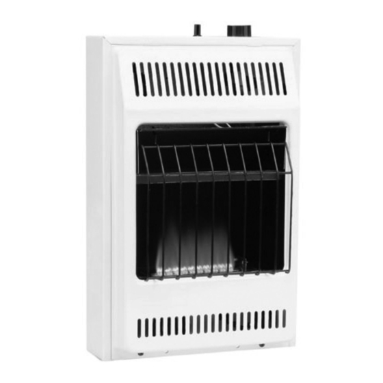
VENT-FREE GAS HEATER
MODELS
GWN10A, GWP10A,
GWN10TA, GWP10TA,
VSHN10M, VSHP10M,
VSHN10T, VSHP10T
PFS
®
US
Advertisement
Table of Contents

Related Manuals for FMI GWN10A


Summary of Contents for FMI GWN10A
- Page 1 VENT-FREE GAS HEATER SAFETY INFORMATION AND INSTALLATION MANUAL ® MODELS GWN10A, GWP10A, GWN10TA, GWP10TA, VSHN10M, VSHP10M, VSHN10T, VSHP10T WARNING: If the information in this manual is not followed exactly, a fire or explosion may result causing property damage, personal injury or loss of life.
-
Page 2: Table Of Contents
TABLE OF CONTENTS Safety ..............2 Cleaning and Maintenance ........ 16 Local Codes............4 Troubleshooting ..........17 Product Identification ........... 4 Specifications ............ 21 Unpacking............4 Replacement Parts ..........21 Product Features ..........4 Service Hints ............. 21 Air For Combustion and Ventilation ..... 5 Technical Service.......... - Page 3 SAFETY Continued Natural and Propane/LP Gas: Natural and Keep the appliance area clear propane/LP gases are odorless. An odor- and free from combustible ma- making agent is added to these gases. The terials, gasoline and other flam- odor helps you detect a gas leak. However, the mable vapors and liquids.
-
Page 4: Local Codes
1. Remove heater from carton. 2. Remove all protective packaging applied to heater for shipment. 3. Check heater for any shipping damage. If heater is damaged call FMI PRODUCTS, LLC at 1-866-328-4537 for replacement parts before returning to dealer. www.fmiproducts.com... -
Page 5: Air For Combustion And Ventilation
AIR FOR COMBUSTION AND VENTILATION Unusually Tight Construction WARNING: This heater shall The air that leaks around doors and windows not be installed in a room or space may provide enough fresh air for combustion and ventilation. However, in buildings of un- unless the required volume of in- usually tight construction, you must provide door combustion air is provided... - Page 6 AIR FOR COMBUSTION AND VENTILATION Continued DETERMINING FRESH-AIR FLOW The space in the example is a confined space because the actual Btu/Hr used is more than the FOR HEATER LOCATION maximum Btu/Hr the space can support. You Determining if You Have a Confined or must provide additional fresh air.
-
Page 7: Installation
AIR FOR COMBUSTION AND VENTILATION Continued IMPORTANT: Do not provide openings for inlet or outlet air into attic if attic has a thermostat- 12" controlled power vent. Heated air entering the attic will activate the power vent. Ventilation Grills Into Adjoining Room, Ventilation Ventilated Option 2... - Page 8 INSTALLATION Continued LOCATING HEATER CAUTION: If you install the This heater is designed to be mounted on a wall. heater in a home garage WARNING: Maintain the • heater pilot and burner must be at minimum clearances shown least 18" (45.7 cm) above floor in Figure 4.
- Page 9 INSTALLATION Continued INSTALLING HEATER TO WALL 3. Insert wall anchor (wings first) into hole. Tap anchor flush to wall. Marking Screw Locations 4. For thin walls [1/2" (1.3 cm) or less], insert WARNING: Maintain minimum red key into wall anchor. Push red key to clearances shown in Figure 8.
- Page 10 INSTALLATION Continued CONNECTING TO GAS SUPPLY Removing Front Panel Of Heater 1. Remove two screws near bottom corners WARNING: This appliance of front panel. requires a 3/8" NPT (National 2. Lift straight up on grill guard until it stops. Grill guard will slide up about 1/4". Pipe Thread) inlet connection to 3.
- Page 11 INSTALLATION Continued Installation must include equipment shutoff 3/8" NPT valve, union and plugged 1/8" NPT tap. Locate Pipe Pressure NPT tap within reach for test gauge hook up. Nipple Regulator NPT tap must be upstream from heater (see Ground Figure 13). Joint IMPORTANT: Install an equipment shutoff Union...
- Page 12 INSTALLATION Continued CHECKING GAS CONNECTIONS 2. Pressurize supply piping system by either opening propane/LP supply tank valve WARNING: Test all gas piping for propane/LP gas or opening main gas valve located on or near gas meter for and connections, internal and natural gas or using compressed air.
-
Page 13: Operation
INSTALLATION Continued PRESSURE TESTING HEATER GAS 4. Check all joints from equipment shutoff CONNECTIONS valve to thermostat gas valve (see Figure 1. Open equipment shutoff valve (see Figure 16 or 17). Apply a noncorrosive leak de- 15). tection fluid to all joints. Bubbles forming show a leak. - Page 14 OPERATION Continued TO TURN OFF GAS Note: If pilot goes out, repeat steps 4 TO APPLIANCE through 7. Wait one (1) minute before light- ing pilot 1. Turn control knob clockwise to the 9. Turn control knob counterclockwise OFF position. to desired heating level.
-
Page 15: Inspecting Heater
INSPECTING HEATERS BURNER FLAME PATTERN Check pilot flame pattern and burner flame patterns often. WARNING: If yellow tipping PILOT FLAME PATTERN occurs, your heater could pro- Figure 20 shows a correct pilot flame pattern. duce increased levels of carbon Figure 21 shows an incorrect pilot flame pat- monoxide. -
Page 16: Cleaning And Maintenance
CLEANING AND MAINTENANCE We also recommend that you keep the burner WARNING: Turn off heater tube and pilot assembly clean and free of dust and dirt. To clean these parts we recommend and let cool before cleaning. using compressed air no greater than 30 PSI. Your local computer store, hardware store or CAUTION: You must keep home center may carry compressed air in a... -
Page 17: Troubleshooting
TROUBLESHOOTING WARNING: Turn off and unplug heater and let cool before servicing. Only a qualified service person should service and repair heater. CAUTION: Never use a wire, needle or similar object to clean ODS/pilot. This can damage ODS/pilot unit. Note: All troubleshooting items are listed in order of operation. OBSERvED PROBLEM POSSIBLE CAUSE REMEDY... - Page 18 TROUBLESHOOTING Continued OBSERvED PROBLEM POSSIBLE CAUSE REMEDY ODS/pilot lights but flame 1. Control knob not fully 1. Press in control knob fully goes out when control knob pressed in is released 2. Control knob not pressed in 2. After ODS/pilot lights, keep long enough control knob pressed in 30 seconds...
- Page 19 TROUBLESHOOTING Continued OBSERvED PROBLEM POSSIBLE CAUSE REMEDY Yellow flame during burner 1. Not enough air 1. Clean burner (see Cleaning combustion and Maintenance, page 16) or replace burner orifice 2. Gas Regulator defective 2. Replace damaged burner 3. Clogged or dirty burner 3.
- Page 20 TROUBLESHOOTING Continued WARNING: If you smell gas • Shut off gas supply. • Do not try to light any appliance. • Do not touch any electrical switch; do not use any phone in your building. • Immediately call your gas supplier from a neighbor’s phone. Fol- low the gas supplier’s instructions.
-
Page 21: Specifications
Contact authorized dealers of this product. • model and serial numbers of your heater If they can’t supply original replacement • how heater was malfunctioning part(s), call FMI PRODUCTS, LLC at • type of gas used (propane/LP or natural 1-866-328-4537. gas) •... -
Page 22: Parts
PARTS MODELS GWN10A, GWP10A, GWN10TA, GWP10TA, VSHN10M, VSHP10M, VSHN10T, VSHP10T *Manual Models **Thermostat Models www.fmiproducts.com 125326-01A... - Page 23 PARTS This list contains replaceable parts used in your heater. When ordering parts, follow the instructions listed under Replacement Parts on page 21 of this manual. GWP10TA GWN10TA GWP10A GWN10A PART NO. DESCRIPTION VSHP10T VSHN10T VSHP10M VSHN10M QTY. 099217-02CP Front Panel •...
-
Page 24: Warranty
FMI PRODUCTS, LLC’s liability is limited to the purchase price of the product, and FMI PRODUCTS, LLC shall not be liable for any other damages whatsoever under any circumstances including indirect, incidental, or consequential damages.
Need help?
Do you have a question about the GWN10A and is the answer not in the manual?
Questions and answers