
Related Manuals for WiT VL53-400


Summary of Contents for WiT VL53-400
- Page 1 USER MANUAL VL53-400 Laser Ranging Sensor VL53-400 | Manual v23-0215 | www.wit-motion.com - 1 -...
-
Page 2: Tutorial Link
AHRS sensors. Contact Technical Support Contact Info Application ● Robot ● UAV ● Intelligent Device VL53-400 | Manual v23-0215 | www.wit-motion.com - 2 -... -
Page 3: Table Of Contents
7 Communication Protocol ............... - 21 - 7.1 Serial Mode ................ - 21 - 7.2 Modbus Protocol ..............- 22 - 7.3 Modbus Register ..............- 24 - 7.4 IIC Mode ................- 27 - VL53-400 | Manual v23-0215 | www.wit-motion.com - 3 -... -
Page 4: Overview
2-layer PCB board process, thinner, smaller and more reliable. Metal shielding cover to prevent static interference. Default short-distance mode (the longest measurement distance is 2 meters), when measuring 4 meters, change to the long-distance mode. VL53-400 | Manual v23-0215 | www.wit-motion.com - 4 -... -
Page 5: Size
2 Size VL53-400 | Manual v23-0215 | www.wit-motion.com - 5 -... -
Page 6: Parameter
0.1~100HZ(default 10Hz) Measuring Distance 40mm-4000mm (4000mm without optical cover) 1.575"-157.480" (157.480"without optical cover) Interface Level TTL Baud Rate Supports 2400-921600, default 115200 Ranging Error ±20mm (±0.787") VL53-400 | Manual v23-0215 | www.wit-motion.com - 6 -... -
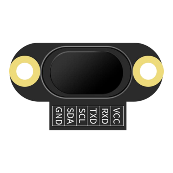
Page 7: Pin
(TT level, not directly connected to RS232 level) can be connected to the RXD of the microcontroller IIC communication clock pin (need to enter IIC mode) IIC communication data pin (need to enter IIC mode) Ground VL53-400 | Manual v23-0215 | www.wit-motion.com - 7 -... - Page 8 Below is the new software and universal instruction download link. https://drive.google.com/drive/folders/1dnwmnH7mi4zBpNqDywLzr zsV7BfeKaD9?usp=share_link Note: The 2022 old version software will be reserved for use. You can check “Chapter 3 Use Instructions with PC” for more details. ↓↓↓ VL53-400 | Manual v23-0215 | www.wit-motion.com - 8 -...
-
Page 9: Hardware Connection
3-in-1 serial converter 6-in-1 serial converter Step 1. Connect the sensor with a serial converter PIN Connection: VCC - GND – GND Step 2. Plug it into computer. PC-serial module connection diagram: VL53-400 | Manual v23-0215 | www.wit-motion.com - 9 -... -
Page 10: Iic Connection
Step 2. Unzip the software and install the driver CH340 https://drive.google.com/file/d/1I3hl9Thsj9aXfG6U-cQLpV9hC3bVEH2V/view? usp=sharing *How to Install and update the CH340 driver Click the "Uninstall" button first. Then click on the "Install" button. VL53-400 | Manual v23-0215 | www.wit-motion.com - 10 -... - Page 11 2)After opening the device manager, you will need to open the Ports (COM & LPT) tree. The CH340 should show up as USB-SERIAL CH340 (COM##). Depending on your computer, the COM port may show up as a different number. VL53-400 | Manual v23-0215 | www.wit-motion.com - 11 -...
-
Page 12: Software Connection
2. To detect fast-moving objects, the sampling frequency should be adjusted (VL53-400 sets the timing preset time and measurement time interval). 3. The laser light source is an invisible beam to the naked eye (the laser can be seen with a mobile phone camera). -
Page 13: Data View
7.2 Data View Step 1. Open the computer, click the corresponding serial. (Default baud rate: 115200) Step 2. Click "Search Device" then view the data, as follows: VL53-400 | Manual v23-0215 | www.wit-motion.com - 13 -... - Page 14 Step 1. Click "Configuration" to select the corresponding device and enter the configuration interface. Step 2. Entering “Device ID” click "Set up". ID can be set in the range 0x00~0x7F. VL53-400 | Manual v23-0215 | www.wit-motion.com - 14 -...
-
Page 15: Reset
Step 1. After connecting the sensor normally, click "Configuration" to enter the configuration interface. Step 2. Click “Reset”, If the baud rate or ID is not the default setting (default baud rate: 115200, ID: 0X50), search for the device again. VL53-400 | Manual v23-0215 | www.wit-motion.com - 15 -... -
Page 16: Baud Rate
After the normal connection, the baud rate can be modified on the computer. Step 1. Click "Configuration" to select the corresponding device and enter the configuration interface. Step 2. Click “Communication rate”, select the baud rate. VL53-400 | Manual v23-0215 | www.wit-motion.com - 16 -... -
Page 17: Return Rate
Modbus mode.) Step 1. After connecting the sensor normally, click "Configuration" to select the corresponding device and enter the configuration interface. Step 2. Click “Return rate”. VL53-400 | Manual v23-0215 | www.wit-motion.com - 17 -... -
Page 18: Calibration Module
14cm (5.512") in front of the sensor and click to calibrate. Step 1. After connecting the sensor normally, click "Configuration" to select the corresponding device and enter the configuration interface. Step 2. Fix the sensor and calibration object, click "Calibration module". VL53-400 | Manual v23-0215 | www.wit-motion.com - 18 -... -
Page 19: Measurement Mode
4 meters. The default setting is long-distance mode. Step 1. After connecting the sensor normally, click "Configure" to select the corresponding device and enter the configuration interface. Step 2. Click “Measurement mode”. VL53-400 | Manual v23-0215 | www.wit-motion.com - 19 -... - Page 20 // Set 7 register is 20 Time delay100ms MODADDR 06 00 08 00 01 CRCH CRCL // Set 8 register is 1 Time delay100ms MODADDR 06 00 36 00 01 CRCH CRCL // Set to short-distance VL53-400 | Manual v23-0215 | www.wit-motion.com - 20 -...
-
Page 21: Communication Protocol
The data returned by the sensor is as follows: For example: d: 490mm 19.291" State: 7, No Update d: 490mm 19.291" means measuring distance State: 7, No Update indicates the status bit of the measurement data VL53-400 | Manual v23-0215 | www.wit-motion.com - 21 -... -
Page 22: Modbus Protocol
DataH DataL ..CRCH CRCL For example: the module address is 0x00, the read command is 0x03, and the length is 2 bits. Command: 50 03 02 00 1C 44 41 VL53-400 | Manual v23-0215 | www.wit-motion.com - 22 -... - Page 23 Data analysis: 0x50 is the Modbus address, 0x03 is sign, 0x02 is the data length, 0x07 0x0B measurement data corresponds to 0x070B is decimal 1803mm (710.079"), the measurement distance is 18036mm (710.079"), and 0x06 0x7F is the CRC check byte. VL53-400 | Manual v23-0215 | www.wit-motion.com - 23 -...
-
Page 24: Modbus Register
CRCH CRCL Write 0x04,baud rate 38400 06 00 04 MODADDR CRCH CRCL Write 0x05,baud rate 57600 06 00 04 MODADDR CRCH CRCL Write 0x06,baud rate 115200 06 00 04 MODADDR CRCH CRCL VL53-400 | Manual v23-0215 | www.wit-motion.com - 24 -... - Page 25 Read:0x04,Sensor Phase Fail Read:0x05, Sensor Hardware Fail Model 0x36 MODADDR 06 00 36 Write 0x00, short distance 00 01 CRCH CRCL 1.3m, better environmental immunity) 06 00 36 Write 0x01, medium distance MODADDR VL53-400 | Manual v23-0215 | www.wit-motion.com - 25 -...
- Page 26 MODADDR 00 01 CRCH CRCL Read: 0x02, calibration failed Read: 0x03, calibration complete System 0x38 06 00 38 Write 0x00, sensor normal MODADDR mode 00 00 CRCH CRCL mode, automatic return VL53-400 | Manual v23-0215 | www.wit-motion.com - 26 -...
-
Page 27: Iic Mode
8.4 IIC Mode When set to IIC mode, the MCU releases the IIC bus of the VL53-400. SDA and SCL are directly connected to the sensor (the internal 10K resistors of SDA and SCL are pulled up). For specific data reading, please refer to the VL53-400 data sheet.
Need help?
Do you have a question about the VL53-400 and is the answer not in the manual?
Questions and answers