Table of Contents
Advertisement
Advertisement
Table of Contents
Troubleshooting

Related Manuals for Sinexcel Energy Freedom PWS1-1725KTL-H-NA-O


Summary of Contents for Sinexcel Energy Freedom PWS1-1725KTL-H-NA-O
- Page 2 Sinexcel PWS1-1725KTL-H-NA-O Bi-directional Power Conversion System User manual Version:V2.0 Filing Date:2023-04 Shenzhen Sinexcel Electric Co., Ltd. All rights reserved. In case of any content change, it shall be without prior notice. Shenzhen Sinexcel Electric Co., Ltd. Website: http://sinexcel.us/ www.sinexcel.com Add: Building 6, Area 2, Baiwangxin High-tech Industrial Park, No. 1002, Songbai Road, Nanshan District,...
-
Page 3: Table Of Contents
Contents 1 OVERVIEW .................................. 1 ..............................1 1.1 A PPLICABLE ODELS ................................1 1.2 T ARGET ROUP ................................2 1.3 T ERMINOLOGY 2. SAFETY INSTRUCTIONS ............................3 2.1 SAFETY INSTRUCTIONS ............................3 ..........................3 2.2 I MPORTANT AFETY NSTRUCTIONS ............................. 5 2.3 A DDITIONAL NFORMATION... - Page 4 6.3.3 Wiring parts ................................. 12 6.3.4 Preparation before wiring ..........................13 6.3.5 Cable Requirements ............................13 6.3.6 Wiring Precautions............................. 14 6.3.7 Wiring Area Overview ............................15 6.3.8 DC side wiring ..............................16 6.3.9 AC side wiring ..............................17 6.3.10 Ground Connection ............................18 6.3.11 Wiring of terminal strips ..........................
- Page 5 ..............................42 10.2 M AINTENANCE CYCLE ......................44 10.3 E LECTRONIC COMPONENTS REPLACEMENT 11 APPENDIX ................................45 ..............................45 11.1 Q UALITY SSURANCE ..................46 11.2 HMI P ROTECTION ARAMETER ETTING NTRODUCTION 12 CONTACT ................................48 INSTALLATION INFO ..............................49...
-
Page 6: Overview
1 Overview 1.1 Applicable Models This file applies to the following models: PWS1-1725KTL-H series models This section describes the product model definitions in this manual, as shown in Fig. 1-1: Fig. 1-1 Product Model For Example: PWS1-1725KTL-H-NA-8M1-O:Indicates that rated capacity of 1725kW bi-directional single stage energy storage converter without transformer, high voltage 1500V outdoor cabinet. -
Page 7: Terminology
1.3 Terminology Terminology Definition Static transfer switches BESS Battery energy storage system Energy storage system Energy management system Battery management system Power Conversion System Single line diagram State of health, expressed in percentage. Silicon controlled rectifier Depth of discharge, expressed in percentage. End of discharge Remaining power, expressed in percentage. -
Page 8: Safety Instructions
2.2 Important Safety Instructions This user manual for the installation and operation of the PWS1 series 1725kW bi-directional Energy Storage Converters from Sinexcel. Please read this user manual carefully before installation. The bi-directional energy storage converters must be commissioned and maintained by an engineer appointed by the manufacturer or an authorized service partner. - Page 9 Any touching of the copper strip, contacts and terminals inside the appliance that are connected to the grid circuit may cause a fatal burn or electric shock! Do not touch any terminals and wires connected to the grid circuit. Take note of any instructions and safety documents regarding grid connection. Contact with the interior of the appliance may present a risk of electric shock! Any operation in connection with this appliance must be carried out by qualified personnel.
-
Page 10: Additional Information
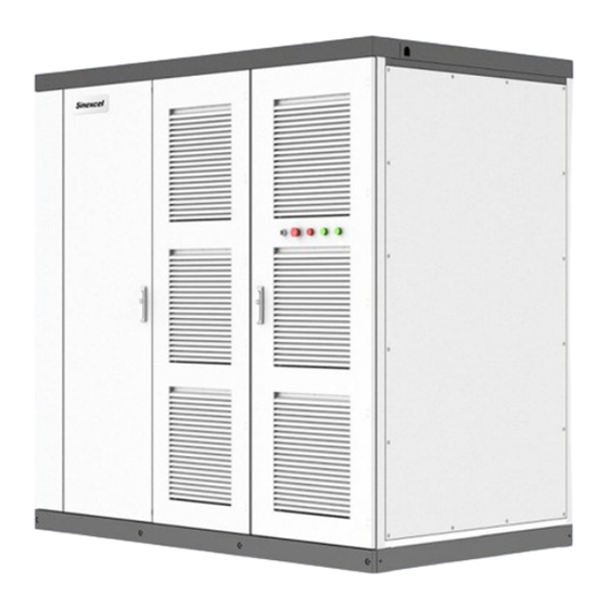
2.3 Additional Information For further details please click: www.sinexcel.us 3 Products 3.1 System Introduction PWS1-1725KTL-H series bi-directional energy storage converter (PCS) is a conversion device between the grid and the battery, which can charge and discharge the battery. It can invert the DC power from the battery into AC power that can be connected to the grid and rectify the AC power from the grid into DC power that can be charged into the battery. - Page 11 AUX knob Control the inverter aux power* The knob is used to control the power supply mode of the auxiliary power supply. When the AUX knob is rotated to ON, the rack auxiliary source supplies power to the control box, and the control box supplies power to the module communication. When the control box is powered on, it can control the DC electric operation switch and the AC electric operation breaker to close.When the AUX knob is rotated to OFF, the DC switch and AC circuit breaker work normally, and the auxiliary power supply of the control box is provided by the module.
-
Page 12: Dimension And Weight
3.3 Dimension and weight The dimension of PWS1-1725KTL-H series energy storage converters are marked as shown in Fig. 3-3. The net weight of the product is about 2390kg, and the specific weight is subject to the actual nominal weight. 2160 2200 1300 Fig. -
Page 13: System Schematic
DC isolation fuse Unit1 Disconnect Switch BAT+ AC Filter Circuit Breaker BAT- AC SPD DC SPD Unit8 Fig. 3-4 Schematic diagram of energy storage converter topology 3.5 System schematic PWS1-1725KTL-H Bi-directional Storage Inverter (PCS) is composed of 8 PCS-AC modules. The modules identify master-slave systems through the DIP switch dial-up codes on the panel. - Page 14 Fig. 3-6 Topological graph for Bi-directional Storage Inverter (PCS) with 8 branch input Fig. 3-7 Topological graph for Bi-directional Storage Inverter (PCS) with 2 branch input...
- Page 15 Fig. 3-8 Topological graph for Bi-directional Storage Inverter (PCS) with 4 branch input Both models have identical mechanical and electrical construction except composed of different sets of PCS-AC modules and rating: PWS1-1725KTL-H series is composed of 8 sets of PCS-AC modules, the DC branches can be selected of 1, 2, 4 or 8 by different number of DC switches.
-
Page 16: Pcs Composition
3.6 PCS Composition Fig.3-9 Visible Components of the PCS Instruction Position Description PCS-AC (1~8 module(s)) 215kW 1 set Battery DC Switch 1, 2, 4 or 8 set of DC Switch AC Switch AUX Power box U2 control PCBA Wiring terminal 3.7 Operating Compositions 3.7.1 Switches Introduction 3.7.1.1 AC switch... - Page 17 CLOSED CHARGED OPEN DISCHARGED Fig. 3-10 Switch positions of the AC disconnection unit Description Instruction Position Switch In On position The AC connection unit is closed. CLOSED OPEN Switch In OFF position The AC disconnection unit is open. Energy storage completion CHARGED Unstored energy DISCHARGED...
- Page 18 Position Description Instruction Switch In On position The DC connection unit is closed. Switch In OFF position The DC disconnection unit is open. Energy storage completion Charged Unstored energy Discharged 3.7.1.3 AUX power supply switch & Fan power switch AUX power supply can be the redundancy power supply through the AC Switch inside the PCS cabinet.
-
Page 19: Labels
AC fuse AC SPD DC fuse DC SPD 3.8 Labels Label Instruction Label-Dot label-L1 phase Label-Dot label-L2 phase Label-Dot label-L3 phase Label-Dot label-Positive electrode Label-Dot label-Negative electrode Label-Dot label-Grounding 3.9 Heat dissipation design PWS1-1725KTL-H-NA-O series energy storage converter is NEMA3R outdoor unit, the whole adopts the structure design of air inlet on the right side door panel and air outlet on the left side door. - Page 20 Fig. 3-13 PWS1-1725KTL-H series energy storage converter ventilation design...
-
Page 21: Parameters
4 Parameters Technical parameters table Product Model PWS1-1725KTL-H-NA-8M1-O DC parameters DC voltage range 1070~1500V Full load voltage range 1070~1500V Maximum DC current 1608/201A each branch Numbers of DC branches 1/2/4/8 Utility-interactive Mode Nominal AC power 1725kVA AC voltage 690V(-15%~10%) AC frequency 50Hz/60Hz(±5Hz) Nominal AC current 1443A... -
Page 22: Storing、Lifting And Transporting
5 Storing、lifting and transporting 5.1 Transport and storage In order to ensure that the energy storage converter is in a better protective state during transportation, please choose to transport with packaging as much as possible, and transport according to the indications of various signs on the packaging. - Page 23 The energy storage converter is a whole device, and it must not be disassembled during transportation or storage. Equipment failures caused by modifications not authorized by Sinexcel are not covered by the warranty. When the equipment is transported and stored, it is strictly forbidden to stack, and no other items are allowed to be stacked on the top of the equipment.
-
Page 24: Transport
5.2 Transport It is recommended to use a forklift to move the entire box body in a short distance without removing the shipping box. When moving, pay attention to the center of gravity mark and lifting mark position on the box, and ensure that the transportation tool has sufficient carrying capacity. - Page 25 0.8m, and the load-bearing capacity of the pallet truck must be ≥2400kg. In the process of using a forklift to fork, lower and move the energy storage converter, it is necessary to ensure that it is slow and stable, and the energy storage converter must be placed on a firm and level ground.
-
Page 26: Out Of The Box Inspection
5.3.2 Inspection Before leaving the factory, the energy storage converter has been checked by the staff of Sinexcel and packed firmly. Nonetheless, the following items need to be checked after the energy storage converter shipping packaging has been removed: Check whether the quantity of each item on the packing list is consistent with the actual item;... -
Page 27: Equipment Installation
Installation and debugging can only be carried out on the energy storage converter that has been inspected correctly and is complete without damage. During the inspection process, if any problem is found, please contact the transporter or Sinexcel in time. 6 Equipment installation 6.1 Installation requirements... -
Page 28: Foundation Support Requirements
When the ambient temperature is higher than 45℃ the machine will run at a reduced rate. When the temperature is lower than -20℃, it needs to warm up first before high power operation. The sunlight irradiation intensity should be ≤1200W/m^2, and it is recommended that the inverter installed outdoors should take the necessary shading measures. -
Page 29: Ventilation Requirements
Fig. 6-1 Bottom view of the PCS 6.1.4 Ventilation requirements The converter will generate a lot of heat when running, and the high temperature will directly affect the electrical performance of the equipment and even damage the equipment, so the ventilation and heat dissipation needs of the equipment should be fully considered when planning the installation environment of the converter to ensure the normal and efficient operation of the equipment. -
Page 30: Site Installation
other equipment and do not affect each other. Cooling ducts should be designed by professionals in advance to avoid placing the cabinet at backflow wind phenomenon. At the same time, each combination must be sealed to prevent air leakage, the choice of sealing materials to withstand the temperature of at least 80 ℃. -
Page 31: Electrical Connection
The fixing of the energy storage converter needs to be done according to the following steps. 1) Select the appropriate tool to transport the energy storage converter to the installation position and align the installation hole. 2) Use M12*50 bolts to fix the energy storage converter on the channel steel or foundation through the base. -
Page 32: Installation Tools
Energy storage converters should only be connected to DC with the permission of the local power company and only after installation by a qualified technician. Only a qualified electrician or a qualified person should make the electrical connections to this product. Please strictly follow the wiring signs inside the device. -
Page 33: Preparation Before Wiring
When connecting the cables, make sure that the connectors are tightened. Inadequate connection or oxidation of the contact surface may cause local heat accumulation, which may lead to fire and combustion. When wiring the power line, use copper wire of appropriate size and use copper terminals to fix it tightly before connecting it to the wiring copper strip. -
Page 34: Wiring Precautions
Mounting bolt Cable Wire diameter requirement specifications Battery side 7 branches, 120mm each; other types of cables can also be selected, M12*40 but the total line diameter must not be less than 840mm 7 branches, 120mm each; other types of cables can also be selected, Battery side DC- M12*40 but the total line diameter must not be less than 840mm... -
Page 35: Wiring Area Overview
After each step of the wiring operation, it should be carefully checked to ensure that the wiring is correct and firm. Incorrect wiring may cause fire and combustion, so please pay attention to the connection order of wiring components. When connecting, make sure that the connections are tight. Inadequate connection or oxidation of the contact surface may cause local heat accumulation and may lead to fire and combustion. -
Page 36: Dc Side Wiring
L2 L3 Fig. 6-5 AC terminal diagram Position Designation Description Battery input positive pole Battery + Battery - Battery input negative pole Phase L1 Phase L2 Phase L3 6.3.8 DC side wiring Before wiring the DC side, the following checks should be performed: ⚫... -
Page 37: Ac Side Wiring
disconnected. ② Confirm that the DC disconnect switch or DC circuit breaker of the energy storage converter is open. ③ Peel off the insulation skin at the end of the cable, the length of the bare cable should be more than the wiring copper nose wire hole depth of about 5 mm. -
Page 38: Ground Connection
and the steps to connect the AC cable are as follows: ① Verify that the grid distribution switch on the AC rear stage of the energy storage converter is off. ② Confirm that the AC and DC disconnect switches of the energy storage converter are both off. ③... - Page 39 Wiring of terminal strips Fig. 6-6 Wring and communication interface position Table 6-3 Definition of terminal strip ports P1 terminal 220V AC auxiliary power supply External Fan control power AC220V P2 terminal P2 Dry contact signal shorting BMS open circuit fault piece shorting Input dry contact...
-
Page 40: Communication
Note: If access is required, the shorting piece needs to be removed! Fig. 6-7 U2 PCBA Wring and communication interface position 6.3.12 Communication When an Ethernet communication solution is selected for a single energy storage converter, only the Ethernet interface of the energy storage converter needs to be connected to the EMS system using a network cable (EIA/TIA568B). -
Page 41: Installation Checklist
Fig. 6-9 Schematic diagram of multiple PCS Ethernet communication scheme 6.3.13 Installation checklist After the PCS is fully installed, at least two staff members are required to conduct a comprehensive inspection of its installation in accordance with the items listed in the table below. The inspection process should be recorded, and once the entries that do not meet the requirements are found, they should be rectified immediately. -
Page 42: Product Operation
7 Product operation 7.1 Check before operation Before the first operation or after completing maintenance and overhaul, the installation of the equipment should be thoroughly checked again. All operations during operation must be performed by professional electrical personnel, and no individual may operate without authorization. -
Page 43: Check The Battery/Grid Side Voltage
Fig. 7-1 Disconnect switch position diagram 7.1.3 Check the Battery/Grid Side Voltage ⚫ Measure the open-circuit voltage of each energy storage battery for compliance and record it accurately. ⚫ Make sure the positive and negative polarity is correct. ⚫ Measure the resistance of the cable between the battery pack junction box and the machine using an ohmmeter with a megohm range and record it accurately. -
Page 44: Power On And Shut Down
7.2 Power on and shut down 7.2.1 Power on After all the above checks before operation meet the requirements, close the cabinet door of the energy storage converter, pull out the cabinet door key and hand it over to a person for proper storage, then the energy storage converter can be switched on. -
Page 45: Operating Mode
The internal capacitor of the energy storage converter stores dangerous energy, and maintenance or overhaul is strictly prohibited within 15 minutes after the end of the execution of the shutdown operation. During normal operation of the equipment, manual disconnection of the AC/DC disconnect switch is strictly prohibited. -
Page 46: Operating Status Introduction
⚫ On/off-grid control The energy storage converter can work in on-grid and off-grid modes. In on-grid mode, the AC side follows the grid voltage. In off-grid mode, PCS outputs constant frequency and constant voltage AC power. ⚫ Charge and Discharge Control The energy storage converter is capable of charging and discharging the battery pack. -
Page 47: Operating State Switching
PWS1-1725KTL-H energy storage converter has a comprehensive fault detection function, and the fault type can be divided into two categories: "shutdown fault" and "non-shutdown fault". When "shutdown fault" occurs, the system enters the shutdown state; when "non-shutdown fault" occurs, the WIFI webpage of the energy storage converter issues alarm information in the background, but does not stop the operation state. -
Page 48: Protection Function
7.4 Protection Function PWS1-1725KTL series energy storage converters have all-round protection function, which can effectively operate when the battery side voltage or grid side voltage is abnormal, and protect the safe operation of energy storage converters until the abnormal condition disappears, and then continue to generate electricity to the grid. -
Page 49: Network Monitoring Introduction
⚫ Reverse polarity fault When the energy storage converter detects a negative DC voltage during the self-test, the energy storage converter will issue an alarm signal and display the fault type on the webpage. After restoring to normal, the energy storage converter should be re-powered for self-test, and it can work normally only after passing. Note: Short-circuiting the device when in the process of power-on operation may lead to damage to the internal devices of the device. -
Page 50: Lan Port Connection
LAN 2: 172.16.1.10 WIFI default state: Name: the product serial number (nameplate) Address: 10.10.10.1 8.3 LAN port connection Take control box LAN2 as an example. The PC is directly connected to the control box LAN port, and the PC port is configured with IPv4 manual settings so that the PC and the control box are in the same network segment:. - Page 51 AC information secondary submenu Displays instantaneous three-phase voltage, instantaneous three-phase current, instantaneous active power, instantaneous reactive power, instantaneous apparent power, instantaneous power factor, instantaneous frequency, as well as the accumulated active charging power capacity and active discharging power capacity so far. Module information secondary submenu Display module operation status, version number.
-
Page 52: Event Logging Menu Introduction
8.5 Event Logging Menu Introduction Click the Event Logging menu to enter the secondary menu display screen for event logging. When there are multiple pages in the secondary menu screen, only the first page screen is displayed in this subsection, and the contents of other pages are listed in full in the description section. - Page 53 Status log secondary submenu Displays the status change log of the PCS. Operation log secondary submenu Displays the log of commands issued to the PCS. Record Export secondary submenu Provides downloading of all record files to the local browser download directory.
-
Page 54: Introduction To Control & Dispatching Menu
8.6 Introduction to control & dispatching menu Click the control & dispatching menu to enter the secondary submenu to set control and dispatching commands. Control command secondary submenu can control the PCS's power on, power off, grid connection, off-grid and fault reset functions (note that the fault reset function should not be used arbitrarily). - Page 55 System setting secondary sub-menu This interface is customized interface, if necessary, please contact our engineers for relevant settings Monitoring and setting secondary submenu Users can set the local IP, subnet mask, network management, server baud rate communication, language, and restore factory settings.
-
Page 56: Introduction To The Operation Strategy Menu
AC setting secondary submenu Used to set the converter power change mode, whether islanding detection is enabled or not, off-grid voltage start mode, as well as the grid over-under voltage and under frequency threshold and time. 8.8 Introduction to the operation strategy menu Clicking on the Operation Mode menu will take you to the secondary submenu, which leads to Control, Tactics and Tertiary Menu Operation mode secondary submenu... -
Page 57: Introduction To Login Menu
Strategy secondary submenu Users can set the charging and discharging status at different times of the day and the corresponding charging and discharging power. Options secondary submenu Users can set up reservation, insulation detector, grid meter, and PV DCDC. 8.9 Introduction to Login Menu Click Login Menu to enter the login menu screen. -
Page 58: Introduction To About This Machine Menu
Observe all safety practices during operation. If, with the help of this manual, you still cannot solve the problem or still have questions, please contact us Sinexcel. In order to provide you with better and faster service, we usually need the following information. -
Page 59: Preliminary Troubleshooting
⚫ Equipment model ⚫ Serial number ⚫ Information on the manufacturer and model of the relevant components connected to the equipment, as well as the configuration of the energy storage batteries. ⚫ Communication type ⚫ Fault information and brief description ⚫... -
Page 60: Common Faults And Troubleshooting Methods
Check the cable connection There is a short circuit at the AC side AC bus overload and control circuit board of the of the PCS or the internal electronic Contact Sinexcel timeout AC side circuit of the PCS for components are damaged problems... -
Page 61: Other Faults
Check and repair or replace the Lightning arrester insurance after the power is AC side lightning arrester fails Contact Sinexcel fault completely cut off inside the equipment Check repair terminals of the DC auxiliary Auxiliary power... -
Page 62: Maintenance
10 Maintenance Due to the influence of ambient temperature, humidity, dust and vibration, the internal components of the energy storage converters might be aging and unable to operate properly, which leads to potential failures. Therefore, it is necessary to carry out routinely and progress regular maintenance of the energy storage converters to ensure the operation and life-expectancy. - Page 63 ⚫ system Check if the main devices are normal ⚫ Check whether the system heat generation is normal by using thermal ⚫ Check the ventilation system Check whether the humidity and dust of the equipment operating environment meet the requirements, and whether all air inlet filters function normally Attention! Must check the ventilation of the inlet and outlet ⚫...
-
Page 64: Electronic Components Replacement
If the components need to be replaced within other manufacturers or different models of the same manufacturer, it must be confirmed by Sinexcel in advance. Otherwise, we will not be responsible for any casualties or property damage that may be caused. -
Page 65: Appendix
11 Appendix 11.1 Quality Assurance Sinexcel (hereinafter referred to as the Company) will repair or replace the product with a new one free of charge if the product fails during the warranty period. ⚫ Evidence Our company requires the customer to present the invoice and date of purchase of the product during the warranty period. -
Page 66: Hmi Protection Parameter Setting Introduction
11.2 HMI Protection Parameter Setting Introduction Table 11-1 DC protection parameters DC control mode Can be selected between "constant current mode" and "constant power mode". Charge and discharge current It can be set from -2100.0A to 2100.0A, negative value means discharge, positive value means charge, and the default value is 0.0. - Page 67 value, and the default value is 0.0000. Simultaneous target frequency Can be set between -0.1000~0.1000 for quasi-simultaneous frequency adjustment, indicating (target frequency + x*target frequency) Hz, x is the set value, and the default value is 0.0000. Grid-connected switch closure delay time Can be set between 0~10000ms, the default value is 0.
-
Page 68: Contact
Current alarm information of the device ⚫ Current AC and DC information of the device ⚫ Software version of the device SHENZHEN SINEXCEL ELECTRIC CO., LTD. Website:www.sinexcel.us Address: Bldg. 6, Baiwangxin Hi-tech Park, 1002 Songbai Rd., Shenzhen China 518000. Postcode: 518055 Hotline: + 86 0755-8651-1588... -
Page 69: Installation Info
Installation info ....................................................................................................................................................................................................................................................................................................................................................................................................................................................................................................................................................................................................................................................................................................................................................................................................................................................................................................................................................................................
Need help?
Do you have a question about the Energy Freedom PWS1-1725KTL-H-NA-O and is the answer not in the manual?
Questions and answers