Table of Contents
Advertisement
Quick Links
Advertisement
Table of Contents
Troubleshooting

Subscribe to Our Youtube Channel
Related Manuals for Sinexcel Energy Freedom S90


Summary of Contents for Sinexcel Energy Freedom S90
- Page 1 S90 Outdoor Cabinet Manual...
- Page 2 Sinexcel Co. S90 Energy Storage Outdoor All-in-One Cabinet User's Manual Version: 1.0 Shenzhen Sinexcel Electric Co. All rights reserved. Contents are subject to change without notice. Shenzhen Sinexcel Electric Co. Company website: www.sinexcel.com Address:Block 6, Block 2, Baiwangxin Hi-Tech Industrial Park, No.1002 Songbai Road, Nanshan District, Shenzhen, China Contact:0755-8651-1588...
-
Page 3: Table Of Contents
CONTENT 1 OVERVIEW ............................... 4 ..........................4 1.1 A PPLICABLE MODELS ............................4 1.2 T ARGET GROUP .............................4 1.3 T ERMINOLOGY 2 SAFETY INSTRUCTIONS ........................5 2.1 S ..............................5 YMBOLS 2.2 I ......................5 MPORTANT AFETY NSTRUCTIONS 2.3 A ..........................6 DDITIONAL NFORMATION 3 PRODUCTS .............................. 7 3.1 S ..........................7 YSTEM... - Page 4 6.3.5 Cable requirements ........................22 6.3.6 Wiring precautions ..........................23 6.3.7 Wiring area overview ........................24 6.3.8 DC Side Wiring ..........................28 6.3.9 AC Measurement Wiring ........................28 6.3.10 Ground Connection ........................29 6.3.11 Communication Interface ......................30 6.3.12 Installation Checklist ........................31 7 PRODUCT OPERATION ........................32 7.1 C ........................32 HECK BEFORE OPERATION...
- Page 5 11.3.4 Maintaining the Fire Hose ......................70 ......................70 11.4 A ONDITIONER AINTENANCE 11.4.1 Maintenance of the air conditioner module structure............... 70 11.4.2 Check Normal operation ......................71 ................. 72 11.5 C OMMON AULTS AND ROUBLESHOOTING MEASURES 12 APPENDIX ............................74 ..........................
-
Page 6: Overview
1 Overview Applicable models This document applies to the following equipment models: S90 Outdoor Cabinet BESS This section describes the product model definitions in this instruction manual, As shown in Figure 1-1. 1.1 Product Model Definition 1.2 Target group The content described in this document should only be operated by professionals. Professionals must have the following skills. -
Page 7: Safety Instructions
2.2 Important Safety Instructions This user manual is about the installation and operation of the SES-90K outdoor cabinet from Sinexcel. Please read this user's manual carefully before installation. The S90 outdoor cabinet must be commissioned and maintained by an engineer designated by the manufacturer or an authorized service partner. -
Page 8: Additional Information
All internal maintenance and servicing of the equipment should be performed by trained personnel. Internal components that require tools to open cannot be maintained by the user. Please read this user manual before operation. Additional Information For additional details, please click: www.sinexcel.com. -
Page 9: Products
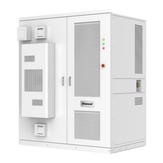
3 Products System Introduction S90 energy storage cabinet is an all-in-one outdoor cabinet system containing bi-directional energy storage inverter module, DCDC PV optimizer module, STS intelligent switching module, battery system, transformer, fire protection system, air conditioning system, auxiliary source power supply and other energy storage batteries. The two-way energy storage converter can charge and discharge the built-in battery system, the DCDC PV optimizer module can access the PV system to store PV power to the battery or power the load through the energy storage converter, and the STS intelligent switching... -
Page 10: System Schematic Diagram
Figure 3.2 External dimensions of the energy storage integrated cabinet 3.4 System Schematic Diagram S90 energy storage outdoor cabinet contains PCS, DC/DC module, ATS, battery pack, SPD protector, GATEWAY and auxiliary power distribution unit, etc. Up to 3 groups of DC/AC module, 3 groups of DC/DC module and 1 ATS are optional. The PCS AC measurement can be connected to the grid or AC load through the isolation transformer, and the PV interface can be directly connected to the PV system. -
Page 11: Technical Specifications
Figure 3.4 Ventilation design of energy storage outdoor cabinet 4 Technical Specifications Technical parameters table Model S90 Outdoor Cabinet BESS DC Side Charging and Discharging 200V-750V (350V-750V @full load) voltage range (Due to the electrical design different with the 30P module) Rated Power 30kW*n (1~3) Maximum Charging and... - Page 12 Operation Temperature Operation Humidity 0-95% (No condensing) Noise 70dB Power Converter Compatibility Sinexcel PWS2-30M-EX Model PWS2-30P-EX/NA Max PCS units 30kW (400 Or 800Vac & 350-750Vdc) *n units (n=1,2,3) AC power range 15kW (400 Or 480Vac & 150-350Vdc) *n units (n=1,2,3)
-
Page 13: Storage, Handling And Transport
5 Storage, Handling and Transport and Storage 5.1 Transport During transportation, in order to ensure that the energy storage outdoor cabinet is in a better protected state, please choose to transport with packaging as far as possible, and transport according to the indication of various markings on the packaging, the illustration of packaging markings is shown in Table 5-1. - Page 14 Energy storage outdoor cabinet for a whole device, transportation or storage are not allowed to break it down. Equipment failure caused by modifications not authorized by Sinexcel Electric is not covered by the warranty.
-
Page 15: Transport
The equipment should be transported and stored in an environment free of corrosive gases, high temperature and heat sources, non-dusty, and in accordance with fire protection requirements. Storage without packaging is strictly prohibited. 5.2 Transport Short distance handling not removed from the transport packaging box of energy storage outdoor cabinet is recommended to preferably use forklift to move the entire box, moving the box should pay attention to the center of gravity mark and lifting mark position, and ensure that the transport tools have sufficient bearing capacity, the use of lifting is strictly prohibited. -
Page 16: Unpacking Inspection
be less than 0.8m and the outer distance shall not be more than 1.2m, and the load-bearing capacity of pallet truck needs to be >1800kg. In the process of using forklift to fork up, put down and move the energy storage outdoor cabinet, make sure that it is slow and smooth, and the energy storage outdoor cabinet must be placed on a solid, flat ground. -
Page 17: Inspection
5.3.2 Inspection Before leaving the factory, the energy storage outdoor cabinet has been checked by Sinexcel Electric staff themselves and packed firmly. Nevertheless, after the removal of energy storage transport packaging still need to inspect the following. Check whether the quantity of each item in the packing list is consistent with the physical object. -
Page 18: Equipment Installation
Only the inspection is correct and complete without damage to the energy storage outdoor cabinet can be installed and commissioned, check the process, once the problem is found, please contact with the transporter or Sinexcel Electric in a timely manner. 6 Equipment installation 6.1 Installation requirements... -
Page 19: Space Requirements
Due to the installation of wall-mounted air conditioning in the battery compartment door of the integrated cabinet, 350mm space is reserved on the side of the battery compartment to ensure the normal opening of the door. The energy storage cabinet needs to be installed on a concrete foundation or a structure supported by steel channel with a surface of flame retardant material. -
Page 20: Ventilation Requirements
Figure 6-2 SES-90 cabinet space requirements Note: The distance E between the air outlet at the bottom of the converter and the ground is required as a minimum space requirement, and this space must be ensured for normal air duct cooling. -
Page 21: Site Installation
installing the cooling duct, cabinet interior should be checked to prevent screws, gaskets and other debris fall during installation process. 6.2 Site installation 6.2.1 Wire channel design The inlet and outlet cables are connected to the cabinet at the bottom. For ease of installation and maintenance, it is recommended that the cables connected with the outside are wired from the cable trench. -
Page 22: Electrical Connection
back front Fixing Channel screws steel Cable trench (a) Schematic diagram of the converter fixed to the channel back front Fixing screws Ground Cable Trench (b) Schematic diagram of the converter fixed to the ground Figure 6-4 Energy storage integrated cabinet fixing method 6.3 Electrical connection 6.3.1 General safety rules Danger of electric shock! -
Page 23: Installation Tools
All electrical connections must comply with the electrical connection standards of the country where the project is located. Energy storage converters should only be connected to DC with the permission of the local power company and only after installation by a qualified technician. Only a qualified electrician or a qualified person should make the electrical connections to this product. -
Page 24: Preparation Before Wiring
When wiring the power line, use copper wire of appropriate size and use copper terminals to fix it tightly before connecting it to the wiring copper strip. 6.3.4 Preparation before wiring Open the back cover of the energy storage outdoor cabinet The user needs to open the lower rear cover of the energy storage converter before wiring. -
Page 25: Wiring Precautions
Photovoltaic side Recommended 4mm each M6*16 208VAC power Recommended 2 x 2.5 mm cable It is strictly forbidden to overload the cable. The current distributed on the 1 mm² cable is strictly forbidden to exceed 3A. 6.3.6 Wiring precautions Before carrying out all electrical wiring, all connected cables must be checked for insulation and integrity. -
Page 26: Wiring Area Overview
After all electrical connections are made, the wiring should be thoroughly inspected and the inlet gaps should be sealed with fireproof mud after confirming that they are correct to prevent small animals from entering. 6.3.7 Wiring area overview The input and output terminals of the energy storage outdoor cabinet are all located at the bottom of the cabinet, and the communication port is located at the bottom of the cabinet, the terminals are arranged as shown in the figure, please wiring correctly according to the logo. - Page 27 Figure 6-1 DC terminal diagram Figure 6-2 AC terminal diagram...
- Page 28 Figure 6-3 Diagram of PE...
- Page 29 Figure 6-5 30P+DCDC wiring physical diagram Figure 6-6 DC Bus wiring physical diagram...
-
Page 30: Dc Side Wiring
6.3.8 DC Side Wiring Before performing DC side wiring, the following checks should be performed. ⚫ Measure the open-circuit voltage of the battery/busbar set to ensure that the open-circuit voltage is within the normal DC voltage range of the energy storage outdoor cabinet. -
Page 31: Ground Connection
Wrong AC side wiring will lead to energy storage outdoor cabinet can not work normally or even damage. Before wiring, make sure the grid side distribution circuit breaker is in disconnected state and the AC and DC disconnect switches are in disconnected state. If there is an "N"... -
Page 32: Communication Interface
6.3.11 Communication Interface S90 outdoor cabinet has Gateway external communication interface, which is located on the right side of the electrical room as shown in the figure. Figure 6-9 External communication port and location diagram When Ethernet communication solution is selected for the S90, it is only necessary to use a network cable (EIA/TIA568B) to connect the Ethernet interface of the Gateway switch to the EMS system. -
Page 33: Installation Checklist
Figure 6-10 Single storage outdoor cabinet Ethernet communication scheme diagram The communication logic between multiple modules and Gateway is shown in the figure below, and the main communication methods are LAN/CAN/RS485. Figure 6-11 Schematic diagram of communication scheme in S90 cabinet 6.3.12 Installation Checklist After all the installation of the energy storage outdoor cabinet is completed, at least two staff members are required to conduct a comprehensive inspection of its installation in accordance... -
Page 34: Product Operation
□ DC positive and negative polarity match the positive and negative polarity of the energy storage outdoor cabinet □ Communication wiring is correct, and keep a certain distance from other cables □ Cable markings are correct and clear □ Insulation shield is complete and reliable, and hazard warning labels are clear and firm Other checks □... -
Page 35: Check The Battery/Grid Side Voltage
Figure 7-1 Disconnect switch position diagram 7.1.3 Check the Battery/Grid Side Voltage ⚫ Measure the open-circuit voltage of each energy storage battery for compliance and record it accurately. ⚫ Make sure the positive and negative polarity is correct. ⚫ Measure the resistance of the cable between the battery pack junction box and the machine using an ohmmeter with a megohm range and record it accurately. -
Page 36: Operation Of The Equipment
Operation of the equipment 7.2.1 Power-up operation Check before powering up: 1) Check that the AC and DC cables are tightly connected according to the installation manual; 2) Test the insulation voltage according to international or local standards, the following parts need to be measured: positive to ground, negative to ground 3) Measure and confirm the voltage on the AC side of the grid, the DC voltage of the battery, and the DC voltage of the PV;... -
Page 37: S90-Gateway Configuration Instructions
Figure 7-3 UPS in S90 ⚫ Close the fire & electric shutter switch QF15 ⚫ Close the AC measurement 24VDC power supply switch QF16 ⚫ Close the bms power supply switch QF14 ⚫ Close battery high voltage box switch ⚫ Close DC side 24VDC supply switch QD1 ⚫... - Page 38 ⚫ Open Windows Settings, click Network and Internet Figure 8-2 Open Network&Internet settings Figure 8-3 Network Connection-Ethernet...
-
Page 39: Ems System Introduction
Figure 8-4 Ethernet Settings Figure 8-5 Internet protocol Settings ⚫ Click on Change Adapter Options Right click on Ethernet (exact naming may vary) - Properties - check Internet Protocol version 4 (TCP/IPv4) and click Properties - Use the following IP address IP address 192.168.1.111 Subnet Mask 255.255.255.0 Default gateway 192.168.1.1... - Page 40 Figure 8-6 website appearance...
-
Page 41: Dashboard
Figure 8-7 website introduction ⚫ Click on the upper right corner of the web page, select option, enter the password 080808, the user can click to modify the configuration system parameters (not necessary for the first time, such as the system parameters have changed when needed) Figure 8-8 website option interface 8.2.1 Dashboard Select the "dashboard"... -
Page 42: Pcs
Figure 8-9 Dashboard interface 8.2.2 PCS The operating status data of PWS2-30P will be displayed in this screen. Figure 8-10 PCS interface 8.2.3 EMS Select "EMS" menu, you can choose manual mode or automatic control mode, strategy in the following figure... -
Page 43: History
Figure 8-11 EMS interface A. Manual control Realize microgrid start, stop and off-grid switching, PCS active and reactive power setting, PV switching and active power setting functions. B. Automatic control Automatically operate under grid-connected and off-grid according to the setting strategy. 8.2.4 History Select the "History"... - Page 44 Figure 8-13 Communication interface Figure 8-14 Debug interface Select "Other" menu, you can configure the network address of Lan2 port, as well as the operation of manual synchronization time and reset. Figure 8-15 Other interface...
-
Page 45: S90 Outdoor Cabinet Ffs
9 S90 Outdoor Cabinet FFS Table 1 Description of fire fighting system components Name Hydrogen exhaust air outlet Fire alarm Air conditioning cooling system Hydrogen exhaust air inlet Explosion relief plate EPO stop button Temperature sensor detector, combustible gas detector Flexible suppression tube Smoke detectors Water fire fighting system... -
Page 46: Troubleshooting
Observe all safety practices during operation. If with the help of this manual,you still cannot solve the problem or still have questions, please contact Sinexcel. In order to provide you with better and faster service, we usually need the following information: ⚫... -
Page 47: Pre-Examination
10.1 Pre-examination When the energy storage converter does not work as expected or the charge/discharge volume changes abnormally, please pay attention to check the following before consulting our maintenance personnel: ⚫ Whether the open circuit voltage of the energy storage battery meets the requirements of the energy storage converter ⚫... -
Page 48: Common Faults And Handling Methods
Table 10-1 Troubleshooting method LED Status Handling method It means that the AC and DC sides of the energy storage converter are not powered. 1. Check whether the power supply and connection of grid and battery are normal. POWER indicator is not on 2. - Page 49 Fault + Manual Fault + PowerOff Warning + Automatic Warning + Manual Warning + PowerOff Alarm name Alarm Alarm cause Alarm troubleshooting classification and clearing method Emergency stop (EPO) 1. EPO interface triggered fault alarm signal; misreported, check whether interface line abnormal Calibration...
- Page 50 and last FLASH flag bits cannot upgrade of PCS; be read; Hardware version 1. PCS key parameters are set 1. If the rated voltage level abnormal incorrectly; 480V (2813 register) incoming mode (2804 register) is set to 3P4W, an alarm will be given; 2. If the offline droop and parallel mode is set and the AC incoming...
- Page 51 module is the same; Check whether authentication region each module is the same as reference standard (2815 and 2816 registers); DSP Parameter mismatch 1. PCS DC parameters are not 1. If the battery type set is set according to the required lithium battery, size relationship;...
- Page 52 specified in the document; Check whether communication line between modules has poor contact; CANB communication fault 1. CAN communication loss Check whether (CAN B comm. Fault) between DSP and monitoring matching resistance chip in PCS; connected specified in the document; 2.
- Page 53 auxiliary controller program burns the correct version; EMS comm. connection 1. Communication between EMS Check whether timeout and PCS is interrupted; 2. EMS connecting wire between is not connected; EMS and PCS is loose; 2. Check whether the EMS is working normally;...
- Page 54 this register to 0; Module Fan fault 1 1. The fan of PCS stops rotating 1. Check whether the PCS fan is blocked by foreign matters and cannot rotate; 2. Clean the dust on the PCS fan; 3. Check whether the PCS fan is damaged and unable to rotate;...
- Page 55 Controller sampling 1. If the sampling of DSP and 1. Set the fault clearing difference auxiliary controller command to PCS and repeat inconsistent, this alarm will be it three times. If it still given; cannot be cleared, contact the manufacturer Battery under energy 1.
- Page 56 2. If this alarm is triggered frequently in a short time during off-network operation, check whether the load capacity is close to specified maximum value; Module current limit alarm 1. PCS detected that AC phase B 1. If this alarm is triggered triggered wave-by-wave current frequently in a short time limiting;...
- Page 57 specified maximum value; Module current limit alarm detected that 1. If this alarm is triggered balance circuit triggered frequently in a short time wave-by-wave current limiting; during off-network operation, check whether the load capacity is close to specified maximum value; Module current abnormal 1.
- Page 58 manufacturer; DC input under voltage 1. The DC voltage is lower than 1. According to the battery the DC lower limit voltage parameters, correctly setting value (1613 register); configure the DC lower limit voltage setting value (1613 register), and the DC lower limit voltage setting value should be lower than the actual...
- Page 59 input 1. PCS internal DC relay open fault occurs, galvanic-break-device circuit fault; contact the manufacturer; open circuit input 1. PCS internal DC relay short fault occurs, galvanic-break-device circuit fault; contact the manufacturer; short circuit input soft 1. The internal DC soft start fault occurs, galvanic-break-device...
- Page 60 (1307 register) is set to 0; Grid overload timeout When AS4777 authentication 1. Check the reason why the mode is selected, the limit active power on the grid feeder function (1327 register) side is greater than the feed is set to 2. If the active power power limit ratio...
- Page 61 grid, which is consistent with phase sequence at the incoming line of the power grid switch. The alarm will be cleared automatically after phase sequence correct; AC bus voltage abnormal 1. This alarm will be given if the 1. If the PCS suddenly instantaneous value of PCS AC disconnects its AC input voltage exceeds the threshold;...
- Page 62 started or operated off the grid. It is necessary to power down and check whether the AC bus is in short circuit; Ac bus neutral loss 1. PCS detects that the AC 1. If the PCS is set to 3P4W, incoming line lacks N;...
-
Page 63: Air Conditioning System Related Faults
PCS is loose, resulting in the grid is seriously distorted. If failure of startup; 3. The IGBT so, wait for the power grid on the AC side of PCS is to return to normal, and damaged, resulting in startup then send the alarm reset failure;... - Page 64 10.3.2.3 Fault alarm content view Figure 10-2 External of alarm indicator identification When a fault alarm occurs, the icon in the lower left corner of the display is always on. If you need to check the content of the fault alarm, you can enter the query interface in the following way: ▲or▼...
- Page 65 Automatic No Condenser middle temperature sensor failure High temperature inside the cabinet Automatic Yes 45℃ Low temperature inside the cabinet Automatic No 0℃ 2.8MP System high voltage alarm Automatic Yes Evaporator freezing Automatic No Internal fan failure Automatic No External fan failure Automatic No Heater failure Automatic No...
- Page 66 is too high maintenance; 3. Failure of the refrigeration 4. Reassess the heat generation and make system; 4. The cabinet has increased adjustments; the heat-generating equipment; 5. Re-evaluate the temperature setting value and 5. Inappropriate temperature deviation; settings; 6. Replace the temperature sensor. 6.
-
Page 67: Other Faults
1. The internal fan stall; Internal fan failure Replace the internal fan 2. Damage to the internal fan. 1. The external fan stall; External fan failure 2. Damage to the external fan. Replace the external fan 1. The ambient humidity is too 1. -
Page 68: Securities & Cautions
11.1 Securities & Cautions Only qualified and authorized personnel are allowed to perform the maintenance. Do not leave metal parts such as screws and washers in the energy storage converter when carrying out maintenance work, otherwise there is a risk of damaging the equipment. Before starting formal maintenance, not only should the AC/DC disconnect switch be disconnected, but also the battery cabinet switch and the grid side distribution switch should be off. -
Page 69: Maintenance Work And Cycle
Maintenance work and cycle 11.2 Check contents How to check Maintenance cycle ⚫ Save software data Save running data, parameters, and logs to related files Once a month ⚫ Check the parameter Settings ⚫ Observe the energy storage converter for damage or deformation ⚫... -
Page 70: Component Inspection
⚫ Check emergency stop knob and LCD touch screen stp funtin Safety features 1 every 6 to 12 ⚫ Simulate the shutdown and check the shutdown signal months niatin ⚫ Optimizing software ⚫ Check the body warning mark and other equipment mark If Software maintenance ⚫... -
Page 71: Check Vents
Figure 11-2 Schematic diagram of the smoke detection module Use a special smoke generator near the smoke sensor module. If the smoke sensor works normally, the red light inside the smok e sensor will be lit for alarm. As shown in Figure 11-3, the fire alarm information will be displayed in the upper right corner of the configuration monitoring page of the system. -
Page 72: Maintaining The Fire Hose
being excluded due to blockage of the air outlet. This module is optional. Figure 11-5 Air exhaust outlet of the cabinet Figure 11-6 Air intake air outlet of the cabinet 11.3.4 Maintaining the Fire Hose The cabinet itself is equipped with a sprinkler device, and the right size of the fuselage is equipped with a fire hose interface. -
Page 73: Check Normal Operation
temperature difference between the inlet and outlet inside and outside the cabinet when the refrigeration system starts; Check whether the fan and compressor work normally when the system is running, and whether there is obvious abnormal sound or jitter; Check whether the mechanical structure is damaged and deformed; check the air conditioning of the internal and external circulation inlet and outlet, the cabinet outside the protective cover of the inlet and outlet screen is blocked;... -
Page 74: Common Faults And Troubleshooting Measures
The temperature in the cabinet is Humidity sensor fault too high or too low The temperature in the cabinet is Humidity alarm too high or too low System high voltage alarm Table 11-1 Fault analysis table Figure 11-8 Exterior cabinet of the air conditioner 11.5 Common Faults and Troubleshooting measures Faults Cause... - Page 75 damaged and unable to rotate module 1.PCS detects overtemperature 1.Ensure the normal operation of PCS isoverheated. of AC radiator; fan; 2.PCS detects overtemperature 2.Ensure that the vent of PCS fan of DC radiator; isunobstructed; 3.Avoid excessively high temperature of PCS operating environment; overload 1.When running...
-
Page 76: Appendix
12 Appendix 12.1 Quality Assurance Ltd. (hereinafter referred to as the Company) will repair or replace the product with a new one free of charge if the product fails during the warranty period. ⚫ Evidence Our company requires the customer to present the invoice and date of purchase of the product during the warranty period. - Page 77 Current alarm information of the device ⚫ Current AC and DC information of the device ⚫ Software version of the equipment Shenzhen Sinexcel Electric Co. Website: www.sinexcel.com Address:Building 6, Zone 2, Baiwangxin Hi-Tech Industrial Park, No.1002 Songbai Road, Nanshan District, Shenzhen, China Zip code:518055...
Need help?
Do you have a question about the Energy Freedom S90 and is the answer not in the manual?
Questions and answers