Advertisement
Introduction
Installation for:
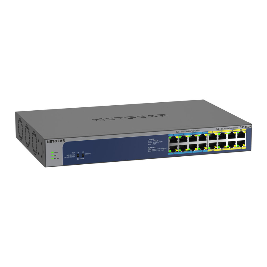
- 16-Port Gigabit Ethernet Unmanaged Ultra60 PoE++ Switch, Model GS516UP

- 24-Port Gigabit Ethernet Unmanaged Ultra60 PoE++ Switch, Model GS524UP


Package contents
- Switch model GS516UP or GS524UP
- Power cord (varies by region)
- Rack-mount kit
- Four rubber feet
- Installation guide and Insight flyer
 Note: We recommend that you use a Category 5e (Cat 5e) cable or higher-rated cable for Gigabit Ethernet connections.
This switch is designed for indoor use only. If you want to connect to a device located outdoors, the outdoor device must be properly grounded and surge protected, and you must install an Ethernet surge protector inline between the switch and the outdoor device. Failure to do so can damage the switch.

Before connecting this switch to outdoor cables or devices, see https://kb.netgear.com/000057103 for safety and warranty information.
Register with the NETGEAR Insight app
- Search for NETGEAR Insight and download the latest app.
- Set up a NETGEAR account if you do not have one.
- Tap the menu in the upper-left corner.
- Tap REGISTER ANY NETGEAR DEVICE.
- Enter the serial number located on the bottom of the switch, or use the camera on your mobile device to scan the serial number bar code.
- Tap GO. The switch is registered and added to your account. You can now view the switch in the NETGEAR Insight app.
Note: Because this is an unmanaged switch, you cannot configure or manage it in NETGEAR Insight.
Connect the switch
Sample connections

Model GS516UP provides PoE++ (802.3bt) power on ports 1–8 with up to 60W to each port and PoE+ (802.3at) power on ports 9–16 with up to 30W to each port. The total PoE power budget for the switch is 380W across all active PoE ports.
Model GS524UP provides PoE++ (802.3bt) power on ports 1–16 with up to 60W to each port and PoE+ (802.3at) power on ports 17–24 with up to 30W to each port. The total PoE power budget for the switch is 480W across all active PoE ports.
Check the LEDs
When you connect the power cord to the switch and plug it into an electrical outlet, the LEDs indicate the status.
| LED | Description | |
| Power |  | Solid green. The switch is powered on and operating normally. Off. Power is not supplied to the switch. |
| Fan |  | Off. The fan is working correctly. Solid yellow. The fan is not working correctly. |
| PoE Max (The status of the switch's PoE budget) |  | Off. Sufficient (more than 7W of) PoE power is available. Solid yellow. Less than 7W of PoE power is available. Blinking yellow. At least once during the previous two minutes, less than 7W of PoE power was available. |
| Left port LED |  | Solid green.1000 Mbps link on this port. Blinking green. 1000 Mbps activity on this port. Solid yellow. 100 Mbps or 10 Mbps link on this port. Blinking yellow. 100 Mbps or 10 Mbps activity on this port. Off. No link is detected on this port. |
| Right Port LED |  | Solid Green. The port is delivering PoE power. Off. The port is not delivering PoE power. Solid yellow. A PoE fault occurred. |
PoE mode
The DIP switches on the front panel let you to select the following PoE++ modes:
- 802.3bt mode. The mode for devices that are fully compliant with IEEE 802.3bt (PoE++). This is the default mode for all PoE++ ports.
- pre-802.3bt mode. The mode for devices that can receive power higher than 30W but that are not fully compliant with IEEE 802.3bt (PoE++).
| PoE++ Mode | DIP Switch Position | Ports 1–4 | Ports 5–8 | Ports 9–12 (GS524UP Only) | Ports 13–16 (GS524UP Only) |
| 802.3bt | Up | Default | Default | Default | Default |
| pre-802.3bt | Down | Optional | Optional | Optional | Optional |
For information about which mode to select, consult the documentation that came with the powered device (PD). If you are not sure, keep the default mode. However, if the PD does not power up, set the DIP switch to the pre-802.3bt mode.
PoE considerations
The PoE power that the switch supplies to powered devices (PDs) is prioritized in ascending port order. If the power requirements for the attached PDs exceed the total power budget of the switch, the PD on the highest-numbered port is disabled to make sure that the PDs connected to the higher-priority, lowernumbered ports are supported first.
A PD listed as an 802.3bt PoE++ powered device does not necessarily require the maximum power limit of the specification. Many PDs require less power, potentially allowing all PoE++ and PoE+ ports to be active simultaneously.
The following table shows the standard power ranges calculated with the maximum cable length of 328 feet (100 meters).
| Device Class | Compatible PoE standard | Class Description | Maximum Power Supplied by the Switch | Power Delivered to the PD |
| 0 | PoE, PoE+, and PoE++ | Default power (full) | 0.44W | 0.44W–12.95W |
| 1 | PoE, PoE+, and PoE++ | Very low power | 4.0W | 0.44W–3.84W |
| 2 | PoE, PoE+, and PoE++ | Low power | 7.0W | 3.84W–6.49W |
| 3 | PoE, PoE+, and PoE++ | Mid power | 15.4W | 6.49W–12.95W |
| 4 | PoE+ and PoE++ | High power | 30.0W | 12.95W–25.5W |
| 5–6 | PoE++ only | Ultra power | 45.0W | 25.5W–51W |
If a device receives insufficient PoE power from the switch, consider using a shorter cable.
May 2020 © NETGEAR, Inc., NETGEAR and the NETGEAR Logo are trademarks of NETGEAR, Inc. Any non‑NETGEAR trademarks are used for reference purposes only.
PoE troubleshooting
Here are some tips for correcting PoE problems that might occur:
- If the PoE Max LED is solid yellow, disconnect one or more PoE devices to prevent PoE oversubscription.
- For each powered device (PD) that is connected to the switch, the associated PoE LED on the switch lights solid green. If the PoE LED lights solid yellow, a PoE fault occurred and PoE halted because of one of the conditions listed in the following table.
| PoE Fault Condition | Possible Solution |
| A PoE-related short circuit occurred on the port. | The problem is most likely with the attached PD. Check the condition of the PD, or restart the PD by disconnecting and reconnecting the PD. |
| The PoE power demand of the PD exceeded the maximum level that the switch permits. The maximum level is 15.4W for a PoE connection, 30W for a PoE+ connection, and 60W for a PoE++ connection. | |
| The PoE current on the port exceeded the classification limit of the PD. | |
| The PoE voltage of the port is outside the range that the switch permits | Restart the switch to see if the condition resolves itself. |
Mount the switch in a rack
We recommend that you use the brackets and screws that came with the switch.
- Attach the supplied mounting brackets to the side of the switch.
- Insert the supplied small screws through each bracket and into the bracket mounting holes in the switch.
- Tighten the screws with a No. 1 Phillips screwdriver to secure each bracket.
- Align the mounting holes in the brackets with the holes in the rack, and insert the provided pan-head screws (you can choose among two types of pan-head screws) with nylon washers through each bracket and into the rack.
- Tighten the screws with a No. 2 Phillips screwdriver to secure mounting brackets to the rack.
Specifications
| Specification | Model GS516UP | Model GS524UP |
| RJ-45 ports | 16 Gigabit Ethernet for 1 Gbps, 100 Mbps, and 10 Mbps. | 24 Gigabit Ethernet for 1 Gbps, 100 Mbps, and 10 Mbps. |
| PoE++ ports | 8 (ports 1–8) | 16 (ports 1–16) |
| PoE+ ports | 8 (ports 9–16) | 8 (ports 17–24) |
| Maximum PoE budget | 380W for the entire switch | 480W for the entire switch |
| AC power input | 100–240V ~ 50/60 Hz, 8–4A | 100–240V ~ 50/60 Hz, 8–4A |
| Dimensions (W x D x H) | 13. 13.0 x 8.2 x 1.7 in. (330 x 207 x 43 mm) | 15. 15.4 x 8.7 x 1.7 in. (390 x 220 x 43 mm) |
| Weight | 5. 5.73 lb (2.6 kg) | 6. 6.83 lb (3.1 kg) |
| Operating temperature | 32–122°F (0–50°C) | |
| Operating humidity | 10%–90% relative humidity, noncondensing | |
| Compliance | FCC class A, UL 62368-1, CB, CE LVD, CE class A, VCCI class A, RCM class A, KC, BSMI | |
Support and Community
Visit netgear.com/support to get your questions answered and access the latest downloads.
You can also check out our NETGEAR Community for helpful advice at community.netgear.com.
Regulatory and Legal
- If this product is sold in Canada, you can access this document in Canadian French at https://www.netgear.com/support/download/.
- For regulatory compliance information including the EU Declaration of Conformity, visit https://www.netgear.com/about/regulatory/.
- See the regulatory compliance document before connecting the power supply.
- For NETGEAR's Privacy Policy, visit https://www.netgear.com/about/privacy-policy.
- By using this device, you are agreeing to NETGEAR's Terms and Conditions at https://www.netgear.com/about/terms-and-conditions. If you do not agree, return the device to your place of purchase within your return period.
- Do not use this device outdoors. The PoE source is intended for intra building connection only.

Documents / Resources
References
Do I need to use a surge protector with my NETGEAR Business device? | Answer | NETGEAR Support
NETGEAR Support | NETGEAR
English - NETGEAR Communities
Download Center | Downloads and Documentation | NETGEAR
Regulatory | NETGEAR
NETGEAR Privacy Policy | NETGEAR
NETGEAR Terms and Conditions | NETGEAR
Download manual
Here you can download full pdf version of manual, it may contain additional safety instructions, warranty information, FCC rules, etc.
Advertisement


Need help?
Do you have a question about the GS516UP and is the answer not in the manual?
Questions and answers