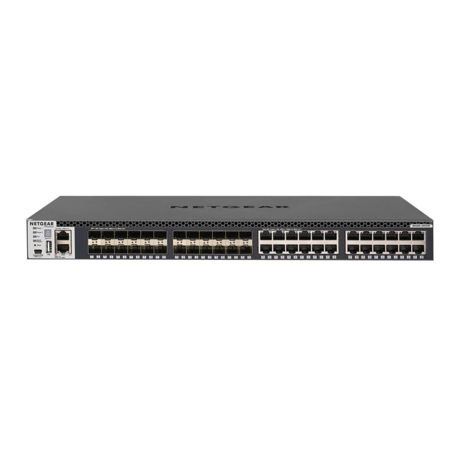
NETGEAR M4300 Intelligent Edge Series Manual
- Hardware installation manual (69 pages) ,
- Installation manual (7 pages)
Advertisement
Step 1. Set up the switch
Prepare the installation site so that mounting, access, power source, and environmental requirements are met.
 NOTE: For more information about these requirements, see the hardware installation guide, which you can download by visiting netgear.com/support/download/.
- Install the switch using one of the following methods:
- On a flat surface. Attach one of the rubber footpads that came with the switch on each of the four concave spaces on the bottom of the switch.
- In a rack. Use the rack-mount kit that is supplied with your switch, following the installation instructions in the hardware installation guide.
- Apply power.
The Power LED lights solid yellow while the switch conducts a power-on selftest (POST). After the POST completes, the Power LED indicates the results:- Solid green: The switch is functional.
- Solid yellow: The POST failed. For more information, see the hardware installation guide.
- No light: Check to see that the power cable or power adapter is plugged in correctly and that the power source is functioning. If this action does not resolve the problem, see the hardware installation guide for more information.
- Connect devices to the switch.
We recommend using the following cables and, if applicable, SFP modules:- Category 5e (Cat 5e) cable for a copper port at 1 Gbps and a Category 5e or better (Cat 5e, Cat 6, Cat 6a, or Cat 7) cable for a copper port at 10 Gbps.
- NETGEAR AGM734 for a copper port at 1 Gbps.
- NETGEAR AGM731F or AGM732F for a fiber port at 1 Gbps.
- NETGEAR AXM761, AXM762, or AXM764 for a fiber port at 10 Gbps.
- NETGEAR AXC761 (1 m), AXC763 (3 m), AXC765 (5 m), AXC767 (7 m), AXC7610 (10 m), AXC7615 (15 m), or AXC7620 (20 m) cable for a fiber port.
NOTE: If purchased, SFP modules and cables are shipped separately. For more information about installing an SFP module, see the hardware installation guide.
Step 2. Log in and configure the switch
You can log in and configure the switch through the out-of-band (OOB) port (which is also referred to as the service port), through any Ethernet network port, or through a console port. By default, the switch functions as a DHCP client.
To log in and configure the switch, use one of the following methods:
- Audio-video user interface: Use the audio-video user interface, abbreviated as AV UI, through the OOB port or any Ethernet network port (see Access the AV UI to configure the switch).
- Main UI: Use the main user interface, abbreviated as main UI, through the OOB port or any Ethernet network port (see Access the main UI to configure the switch).
- CLI: Use the command-line interface (CLI) through the Type-C USB console port. You can configure the IP address manually or use the ezconfig utility (see Access the CLI to configure the switch).
NOTE: For AV installations only, you can use the Engage controller to configure and manage M4300 series switches and other NETGEAR fully managed switches. For more information, visit netgear.com/business/solutions/engage-controller/.
NOTE: Regardless of the management method that you use, make sure that the switch is running the latest firmware version. To download firmware, visit netgear.com/support/download/.
Access the AV UI to configure the switch
You can use a computer on the same subnet as the switch to access the AV UI over the switch's default IP address.
- Configure your computer with a static IP address:
- For access over an Ethernet network port, use an IP address in the 169.254.0.0 subnet with subnet mask 255.255.0.0. For example, use 169.254.100.201.
- For access over the OOB port, use an IP address in the 192.168.0.0 subnet with subnet mask 255.255.0.0. For example, use 192.168.0.201.
- Connect an Ethernet cable from an Ethernet port on your computer to the OOB port or an Ethernet network port on the switch:
- Launch a web browser and enter the default IP address of the switch in the address field of the browser:
- Ethernet port: For access over an Ethernet network port, enter http://169.254.100.100.
- OOB port: For access over the OOB port, enter http://192.168.0.239.
The login page displays.
- To log in for the first time, enter admin for the user name and leave the password field blank, and
- Click the AV UI Login button.
On first login, you are required to specify a password. - Specify a password and log in again using your new password.
- Configure the switch settings.
On each UI page, if you make changes, be sure to save the changes.
NOTE: For information about using the AV UI, including information about assigning a static IP address to the switch, see the audio video user manual, which you can download by visiting netgear.com/support/download/.
Access the main UI to configure the switch
You can use a computer on the same subnet as the switch to access either the main UI over the switch's default IP address.
- Configure your computer with a static IP address:
- For access over an Ethernet network port, use an IP address in the 169.254.0.0 subnet with subnet mask 255.255.0.0. For example, use 169.254.100.201.
- For access over the OOB port, use an IP address in the 192.168.0.0 subnet with subnet mask 255.255.0.0. For example, use 192.168.0.201.
- Connect an Ethernet cable from an Ethernet port on your computer to the OOB port or an Ethernet network port on the switch:
- Launch a web browser and enter the default IP address of the switch in the address field of the browser:
- Ethernet port: For access over an Ethernet network port, enter 169.254.100.100.
- OOB port: For access over the OOB port, enter 192.168.0.239.
The login page displays.
- To log in for the first time, click the Main UI Login button.
The main UI login page displays in a new tab. - Enter admin for the user name, leave the password field blank, and click the Login button.
On first login, you are required to specify a password. - Specify a password and log in again using your new password.
- Configure the switch settings.
On each UI page, if you make changes, be sure to save the changes.
NOTE: For information about using the main UI, including information about assigning a static IP address to the switch, see the main user manual, which you can download by visiting netgear.com/support/download/.
Access the CLI to configure the switch
To use the CLI for initial configuration and assign a static or dynamic IP address to the switch, connect a computer or VT100/ANSI terminal to one of the console ports on the switch.
- Depending on the connector type at your computer or terminal, and the port that you are using on the switch, use one of the following cables, both of which are included in the product package:
- USB console cable for use with the Type-C USB console port.
![warning]() NOTE: To use the Type-C USB port, you might need to install the USB console driver on the computer. You can download the driver by visiting netgear.com/support/download/.
NOTE: To use the Type-C USB port, you might need to install the USB console driver on the computer. You can download the driver by visiting netgear.com/support/download/. - Console cable for use with the RJ-45 RS232 console port.
- USB console cable for use with the Type-C USB console port.
- Connect one end of the cable to the appropriate port on the switch and connect the other end to your computer or terminal.
- If you connect a computer to a console port on the switch, start a terminal emulation program:
- On a computer with a Windows operating system, you can use HyperTerminal or Tera Term.
- On a computer with a Mac operating system, you can use ZTerm.
- On a computer with a Linux operating system, you can use Minicom.
- Configure the terminal emulation program to use the following settings: baud rate, 115,200 bps; data bits, 8; parity, none; stop bit, 1; flow control, none.
- At the user prompt, log in to the switch using the user name admin and press Enter. At the password prompt, do not type a password but press Enter.
On first login, the switch forces you to specify a password. - Specify a password and log in again using your new password
You can now use the CLI to manually configure the switch, including the IP address.
To use the ezconfig utility, continue with the next step. - At the next command prompt, type ezconfig and press Enter.
The ezconfig utility is now running on the switch.
Netgear Switch) #ezconfig
EZ Configuration Utility - Using the ezconfig utility, set up the basic switch configuration, including a static IP address and subnet mask.
You can also use the switch IP address that you manually configure in the CLI or that is assigned by the ezconfig utility to log in to the switch's AV UI or main UI by launching a web browser and entering http://<ipaddress> in the address field.
Find the DHCP-assigned IP address
By default, the switch functions as a DHCP client and gets its IP address from a DHCP server in the network. To find the assigned IP address of the switch's OOB port or management interface (which can be any of the Ethernet ports), connect a computer or VT100/ANSI terminal to one of the console ports on the switch.
- Make sure that the switch is connected to a DHCP server.
- Set up a console connection with the switch.
For information about setting up a console connection, see Steps 1 through 6 in Access the CLI to configure the switch. After you are logged in and at the CLI command prompt, continue with the next step. - At the command prompt, do one of the following:
- To find the IP address of the OOB port (which is also referred to as the service port), type the show serviceport command, and press Enter.
- To find the IP address of the management interface, enter the privileged EXEC mode by typing enable, type the show ip management command, and press Enter.
The IP address that is assigned by the DHCP server displays.
- Log in to the switch's AV UI or main UI by launching a web browser and entering http://<ipaddress> in the address field:
- OOB port: Enter the IP address that is assigned to the OOB port.
- Any Ethernet network port: Enter the IP address that is assigned to the management interface.
Support and Community
Visit netgear.com/support to get your questions answered and access the latest downloads.
You can also check out our NETGEAR Community for helpful advice at community.netgear.com.
Documents / Resources
References
Download Center | Downloads and Documentation | NETGEAR
Engage Controller - NETGEAR ProAV
NETGEAR Support | NETGEAR
English - NETGEAR Communities
Download manual
Here you can download full pdf version of manual, it may contain additional safety instructions, warranty information, FCC rules, etc.
Advertisement


Need help?
Do you have a question about the M4300 Intelligent Edge Series and is the answer not in the manual?
Questions and answers