Advertisement
Table of Contents
•
5216 Portside Dr., Medina, OH 44256 USA
Directions for maintenance, cleaning, storage and use of your Changing Table are also included.
BEFORE STARTING THE ASSEMBLY PROCEDURE, READ ALL DIRECTIONS WITH CARE.
YOU WILL NEED THE FOLLOWING FOR THE ASSEMBLY OF YOUR CHANGING TABLE:
A
(1) Allen Wrench
E
F
(2) Nylon Washer
(1) Dressing Pad
H
(1) End Assembly-Right
K
(1) Top Front Rail
L
(1) Top Shelf Front Rail
M
(4) Lower Front Back Rail
Division of Foundations
•
PH: 1 877.716.2757 (U.S. Only) or +1 330.722.5033
•
www.childcraftbaby.com
Assembly Directions and Parts List
#2 PHILLIPS SCREWDRIVER - FLAT TIPPED SCREWDRIVER
Parts packed in carton and hardware bag
B
(16) Allenhead Bolts
Parts packed in carton
I
(1) End Assembly-Left
No groove in face
Note wide groove
Note narrow groove
Worldwide, Inc.
®
C
(2) Allenhead Bolts
G
(1) Belt
J
(1) Top Back Assembly
N
(1) Top Shelf
O
(2) Lower Shelf
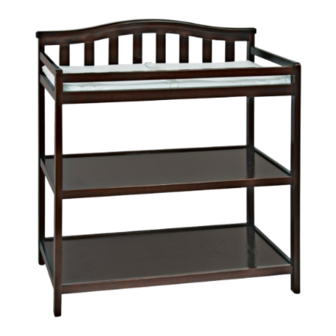
Dressing Table
F01216
•
FAX: +1 330.722.5037
D
(2) Hex Nut
P
(1) Tip Kit
Holes in face
1
AB20312A
Advertisement
Table of Contents

Related Manuals for Child Craft F01216


Summary of Contents for Child Craft F01216
- Page 1 Dressing Table F01216 Division of Foundations Worldwide, Inc. ® • • • 5216 Portside Dr., Medina, OH 44256 USA PH: 1 877.716.2757 (U.S. Only) or +1 330.722.5033 FAX: +1 330.722.5037 • www.childcraftbaby.com Assembly Directions and Parts List Directions for maintenance, cleaning, storage and use of your Changing Table are also included.
- Page 2 rePArAtion Carefully remove and lay out all hardware and parts. Check quantities and match the Hardware List and the Parts List. NOTE: During the assembly process, when using screws or bolts, check each with the P list by letter and size Arts ncloseD in ArDwAre...
- Page 3 2 - D 2: s iAgrAm Helf ssembly Slide Shelves O and N into receiving grooves as shown. Note holes through face in this part. Slide shelf into groove in End Assembly - Right Slide into grooves. 3 - D 3: A iAgrAm ttAcHing...
- Page 4 Step 4 Diagram 4: RECOMMENDED LOCATION OF ATTACHMENT OF TIP RESTRAINT BRACKETS 3/8” 9.5mm 5/64” 0” 0 mm Determine location of 2 wall studs if possible. If not possible, purchase an appropriate anchor system as explained in Step 2 of the WALL STUD SAFETY BRACKET INSTRUCTIONS. Brackets mounted on Dressing Table must be equal distant from the center (C) of Dressing Table.
- Page 5 5 - D 5: A Using restrAint beLT iAgrAm ttAcHing Align the holes in each end of Restraint Belt G with the holes in the Top Shelf N. Attach by inserting Washer E on Bolt C then through the hole in the Top Shelf N. Secure using a Hex Nut D threaded onto Allenhead Bolt C from the underside as shown. Tighten securley. NOTE: Style of Dressing Table may vary.
- Page 6 WARNING ● Read all instructions before use of the changing table. ● Failure to follow these warnings and assembly instructions could result in serious injury or death. ● FALL HAZARD: Children have suffered serious injuries after falling from changing tables. Falls can happen quickly.
Need help?
Do you have a question about the F01216 and is the answer not in the manual?
Questions and answers