Advertisement
Quick Links
Advertisement

Related Manuals for National Instruments PCI-7330


Summary of Contents for National Instruments PCI-7330
- Page 1 PCI-7330...
- Page 2 Motion Control National Instruments 7330 User Manual NI 7330 User Manual October 2003 Edition Part Number 370837A-01...
- Page 3 Thailand 662 992 7519, United Kingdom 44 0 1635 523545 For further support information, refer to the Technical Support and Professional Services appendix. To comment on the documentation, send email to techpubs@ni.com. © 2003 National Instruments Corporation. All rights reserved.
- Page 4 The reader should consult National Instruments if errors are suspected. In no event shall National Instruments be liable for any damages arising out of or related to this document or the information contained in it.
- Page 5 These classes are known as Class A (for use in industrial-commercial locations only) or Class B (for use in residential or commercial locations). All National Instruments (NI) products are FCC Class A products. Depending on where it is operated, this Class A product could be subject to restrictions in the FCC rules. (In Canada, the Department of Communications (DOC), of Industry Canada, regulates wireless interference in much the same way.) Digital...
- Page 6 About the 7330 Controller .....................1-1 Features......................1-1 Hardware ......................1-1 RTSI ........................1-2 What You Need to Get Started ..................1-2 Software Programming Choices ..................1-3 National Instruments Application Software ..............1-3 Optional Equipment .......................1-4 Motion I/O Connections ....................1-4 Chapter 2 Configuration and Installation Software Installation ......................2-1 Controller Configuration....................2-1...
- Page 7 Contents Axes and Motion Resources..................4-3 Axes ........................ 4-3 Motion Resources ................... 4-4 Host Communications ....................4-4 Chapter 5 Signal Connections Motion I/O Connector ....................5-1 Motion Axis Signals..................5-3 Limit and Home Inputs ................... 5-5 Wiring Concerns................5-5 Limit and Home Input Circuit ............5-6 Encoder Signals....................
- Page 8 About This Manual This manual describes the electrical and mechanical aspects of the PXI/PCI-7330 and contains information about how to operate and program the device. The 7330 is designed for PXI, compact PCI, and PCI bus computers. Conventions The following conventions appear in this manual: <>...
- Page 9 About This Manual italic Italic text denotes variables, emphasis, a cross reference, or an introduction to a key concept. This font also denotes text that is a placeholder for a word or value that you must supply. Text in this font denotes text or characters that you should enter from the monospace keyboard, sections of code, programming examples, and syntax examples.
- Page 10 Introduction This chapter includes information about the features of the National Instruments PXI/PCI-7330 controller and information about operating the device. About the 7330 Controller The 7330 controller features advanced motion control with easy-to-use software tools and add-on motion VI libraries for use with LabVIEW.
- Page 11 Additionally, the 7330 analog inputs can provide feedback for loop closure. RTSI The 7330 supports the National Instruments Real-Time System Integration (RTSI) bus. The RTSI bus provides high-speed connectivity between National Instruments products, including image acquisition (IMAQ) and data acquisition (DAQ) products.
- Page 12 National Instruments offers NI-Motion driver software support for LabVIEW, which includes a series of virtual instruments (VIs) for using LabVIEW with National Instruments motion control hardware. The NI-Motion VI library implements the full NI-Motion API and a powerful set of demo functions; example programs; and fully operational, high-level application routines.
- Page 13 Chapter 1 Introduction Optional Equipment National Instruments offers a variety of products for use with the 7330 controller, including the following accessories: • Cables and cable assemblies for motion and digital I/O • Universal Motion Interface (UMI) wiring connectivity blocks with integrated motion signal conditioning and motion inhibit functionality •...
- Page 14 Configuration and Installation This chapter describes how to configure and install the PXI/PCI-7330. Software Installation Before installing the 7330, install the NI-Motion driver software. Refer to the Getting Started with NI Motion Control manual, which is included with the controller, for specific installation instructions.
- Page 15 Misuse of the device can result in a hazard. You can compromise the safety protection built into the device if the device is damaged in any way. If the device is damaged, return it to National Instruments (NI) for repair. Do not substitute parts or modify the device except as described in this document.
- Page 16 Working voltage is the highest rms value of an AC or DC voltage that can occur across any particular insulation. MAINS is defined as a hazardous live electrical supply system that powers equipment. Suitably rated measuring circuits may be connected to the MAINS for measuring purposes. © National Instruments Corporation NI 7330 User Manual...
- Page 17 Chapter 2 Configuration and Installation Hardware Installation Install the 7330 in any open compatible expansion slot in the PXI or PCI system. Appendix A, Specifications, lists the typical power required for each controller. The following instructions are for general installation. Consult the computer user manual or technical reference manual for specific instructions and warnings.
- Page 18 If required, screw the mounting bracket of the controller to the back panel rail of the computer. Replace the cover. Plug in and power on the computer. © National Instruments Corporation NI 7330 User Manual...
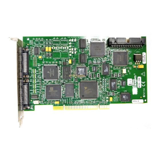
- Page 19 Hardware Overview This chapter presents an overview of the PXI/PCI-7330 functionality. Figures 3-1 and 3-3 show the PXI-7330 and PCI-7330 parts locator diagrams, respectively. 1 Serial Number Label 4 68-Pin Digital I/O Connector 2 DSP 5 68-Pin Motion I/O Connector 3 CPU Figure 3-1.
- Page 20 3 Symbol to Alert User to Read the Manual 8 68-Pin Motion I/O Connector 4 Symbol Indicating FFC Compliance 9 CPU 5 Identification Number Used in Australia 10 DSP Figure 3-3. PCI-7330 Parts Locator Diagram NI 7330 User Manual ni.com...
- Page 21 Signal Connections, for details about the signals in the digital I/O connector. The PCI-7330 RTSI connector provides up to eight triggers to facilitate synchronization between multiple National Instruments products. The PXI-7330 RTSI-enabled connection provides up to eight triggers and one PXI star trigger to facilitate synchronization between multiple National Instruments PXI-enabled products.
- Page 22 Motion tasks are prioritized. Task execution order depends on the priority of each task, the state of the entire motion system, I/O or other system events, and the real-time clock. © National Instruments Corporation NI 7330 User Manual...
- Page 23 Chapter 4 Functional Overview The DSP chip is a separate processor that operates independently from the CPU but is closely synchronized. The 7330 is a true multiprocessing and multitasking embedded controller. Refer to the NI-Motion User Manual for more information about the features available on the 7330.
- Page 24 The 7330 supports axes with secondary output resources. Defining two output resources is useful when controlling axes with multiple motors. Note Refer to the NI-Motion User Manual for more information about configuring axes. © National Instruments Corporation NI 7330 User Manual...
- Page 25 Chapter 4 Functional Overview Motion Resources Encoder, ADC, and motion I/O resources that are not used by an axis are available for non-axis or nonmotion-specific applications. You can directly control an unmapped ADC as a general-purpose analog input (±10 V) to measure potentiometers or other analog sensors.
- Page 26 Signal Connections This chapter includes instructions on how to make input and output signal connections directly to the PXI/PCI-7330 as well as general information about the associated I/O circuitry. The 7330 has three connectors that handle all signals to and from the external motion system: •...
- Page 27 Chapter 5 Signal Connections Figure 5-1 shows the pin assignments for the 68-pin motion I/O connector on the 7330. Table 5-1 includes descriptions for each of the signals. A line above a signal name indicates that the signal is active-low. Axis 1 Dir (CCW) Axis 1 Step (CW) Digital Ground...
- Page 28 Axis <1..4> Step (CW) and Dir (CCW)—These open-collector signals are the stepper command outputs for each axis. The 7330 supports both major industry standards for stepper command signals: step and direction, or independent CW and CCW pulse outputs. © National Instruments Corporation NI 7330 User Manual...
- Page 29 Chapter 5 Signal Connections The output configuration and signal polarity is software programmable for compatibility with various third-party drives, as follows: – When step and direction mode is configured, each commanded step (or microstep) produces a pulse on the step output. The direction output signal level indicates the command direction of motion, either forward or reverse.
- Page 30 These inputs are part of a system solution for complete motion control. Caution National Instruments recommends using limits for personal safety, as well as to protect the motion system. Wiring Concerns For the end of travel limits to function correctly, the forward limit must be located at the forward or positive end of travel, and the reverse limit at the negative end of travel.
- Page 31 Encoder Signals The 7330 offers four channels of single-ended quadrature encoder inputs. All National Instruments power drives and UMI accessories provide built-in circuitry that converts differential encoder signals to single-ended encoder signals. Each channel consists of a Phase A, Phase B, and Index input, as described in the following sections.
- Page 32 Find Reference routine, the position of the Index signal is captured accurately. Use this captured position to establish a reference zero position for absolute position control or any other motion system position reference required. © National Instruments Corporation NI 7330 User Manual...
- Page 33 3.05 m (10 ft). Shielded, 24 AWG wire is the minimum recommended size for the encoder cable. Cables with twisted pairs and an overall shield are recommended for optimized noise immunity. All National Instruments power drives and UMI accessories provide built-in circuitry that converts differential encoder signals to single-ended encoder signals.
- Page 34 An available 7330 position mode is to move an axis Relative to Captured Position. © National Instruments Corporation NI 7330 User Manual...
- Page 35 Chapter 5 Signal Connections The polarity of the trigger input is programmable in software as active-low (inverting), active-high (non-inverting), rising, or falling edge. You also can use a trigger input as a latching general-purpose digital input by simply ignoring the captured position. •...
- Page 36 From the external 1/8 W connector shutdown pin DGND Figure 5-6. Shutdown Input Circuit 3.3 kΩ 74AS760 To the external From the connector breakpoint breakpoint pins circuits Figure 5-7. Breakpoint Output Circuit © National Instruments Corporation 5-11 NI 7330 User Manual...
- Page 37 Chapter 5 Signal Connections Analog Inputs The 7330 has the following ADC input signals: • Analog Input <1..4>—The 7330 includes an eight-channel multiplexed, 12-bit ADC capable of measuring ±10 V, ±5 V, 0–10 V, and 0–5 V inputs. ADC channels 1 through 4 are brought out externally on the 68-pin motion I/O connector.
- Page 38 The host +5 V signal is limited to <100 mA and should not be used to power any external devices, except those intended in the host bus monitor circuits on the UMI and drive products. © National Instruments Corporation 5-13 NI 7330 User Manual...
- Page 39 Chapter 5 Signal Connections Digital I/O Connector All the general-purpose digital I/O lines on the 7330 are available on a separate 68-pin digital I/O connector. Figure 5-8 shows the pin assignments for this connector. +5 V Digital Ground PCLK Digital Ground Reserved Digital Ground Reserved...
- Page 40 The PXI-7330 uses the PXI chassis backplane to connect to other RTSI-capable devices. The PCI-7330 uses a ribbon cable to connect to other RTSI-capable PCI devices. RTSI Signal Considerations The 7330 motion controller allows you to use up to eight RTSI trigger lines as sources for trigger inputs, or as destinations for breakpoint outputs and encoder signals.
- Page 41 Chapter 5 Signal Connections 200 ns Figure 5-9. Breakpoint across RTSI Encoder and Index signals are output-only signals across RTSI that are the digitally-filtered versions of the raw signals coming into the controller. If you are using the RTSI bus for trigger inputs or generic digital I/O, all signals are passed through unaltered.
- Page 42 Specifications This appendix lists the hardware and software performance specifications for the PXI/PCI-7330. Hardware specifications are typical at 25 °C, unless otherwise stated. Stepper Performance Trajectory update rate range ....62.5 to 500 µs/sample Maximum update rate ..... 62.5 µs/axis 4-axis update rate ......
- Page 43 Appendix A Specifications Voltage range........0 to 5 V Output low voltage ....<0.6 V at 64 mA sink Output high voltage....Open collector with built-in 3.3 kΩ pull-up to +5 V Polarity ..........Programmable, active-high or active-low System Safety Watchdog timer function ......Resets board to startup state Watchdog timeout ......63 ms Shutdown input Voltage range........0 to 5 V...
- Page 44 Output low voltage ....<0.6 V at 64 mA sink Output high voltage ....Open collector with built-in 3.3 kΩ pull-up to +5 V Polarity..........Programmable, active-high or active-low Control ..........MustOn/MustOff or automatic when axis off © National Instruments Corporation NI 7330 User Manual...
- Page 45 Appendix A Specifications Analog inputs Number of inputs......8 multiplexed, single ended Number for user signals ...4 ...4 Number for system diagnostics Voltage range (programmable)..±10 V, ±5 V, 0–10 V, 0–5 V Input resistance........10 kΩ min Input coupling........DC Resolution........12 bits, no missing codes Monotonic........Guaranteed Multiplexor scan rate.......25 µs/enabled channel Analog reference output ......7.5 V (nominal) @ 5 mA...
- Page 46 Power consumption........ 5.7 W Physical Dimensions (Not Including Connectors) PXI-7330..........16 × 10 cm (6.3 × 3.9 in.) PCI-7330 ..........17.5 × 9.9 cm (6.9 × 3.9 in.) Connectors Motion I/O connector......68-pin female high-density VHDCI type 32-bit digital I/O connector....68-pin female high-density...
- Page 47 Appendix A Specifications Maximum Working Voltage Channel-to-earth ........12 V, Installation Category 1 (signal voltage plus common-mode voltage) Channel-to-channel.........22 V, Installation Category 1 (signal voltage plus common-mode voltage) Caution These values represent the maximum allowable voltage between any accessible signals on the controller. To determine the acceptable voltage range for a particular signal, refer to the individual signal specifications.
- Page 48 Refer to the Declaration of Conformity (DoC) for this product for any additional regulatory compliance information. To obtain the DoC for this product, visit , search by model number or product line, and click the ni.com/hardref.nsf appropriate link in the Certification column. © National Instruments Corporation NI 7330 User Manual...
- Page 49 Cable Connector Descriptions This appendix describes the connector pinout for the cables that connect to the PXI/PCI-7330. Figure B-1 shows the pin assignments for the stepper 50-pin motion connectors. These connectors are available when you use the SH68-C68-S shielded cable assembly and the 68M-50F step/servo bulkhead cable adapter.
- Page 50 Technical Support and Professional Services Visit the following sections of the National Instruments Web site at for technical support and professional services: ni.com Support—Online technical support resources include the following: • – Self-Help Resources—For immediate answers and solutions, visit our extensive library of technical support resources available in English, Japanese, and Spanish at .
- Page 51 Appendix C Technical Support and Professional Services If you searched and could not find the answers you need, contact ni.com your local office or NI corporate headquarters. Phone numbers for our worldwide offices are listed at the front of this manual. You also can visit the Worldwide Offices section of to access the branch ni.com/niglobal...
- Page 52 (1) active-low a signal is active when its value goes low (0) analog-to-digital converter © National Instruments Corporation NI 7330 User Manual...
- Page 53 Glossary address character code that identifies a specific location (or series of locations) in memory or on a host PC bus system amplifier the drive that delivers power to operate the motor in response to low level control signals. In general, the amplifier is designed to operate with a particular motor type—you cannot use a stepper drive to operate a DC brush motor, for instance Analog Input <1..4>...
- Page 54 I/O port a group of digital input/output signals dynamically-linked library—provides the API for the motion control boards drivers software that communicates commands to control a specific motion control board Digital Signal Processor © National Instruments Corporation NI 7330 User Manual...
- Page 55 Glossary encoder device that translates mechanical motion into electrical signals; used for monitoring position or velocity in a closed-loop system encoder resolution the number of encoder lines between consecutive encoder indexes (marker or Z-bit). If the encoder does not have an index output the encoder resolution can be referred to as lines per revolution.
- Page 56 1,000, or 10 , used with units of measure such as volts, hertz, and meters kilo—the prefix for 1,024, or 2 , used with B in quantifying data or computer memory © National Instruments Corporation NI 7330 User Manual...
- Page 57 Glossary LIFO Last-In, First-Out limit switch/ sensors that alert the control electronics that physical end of travel is being end-of-travel position approached and that the motion should stop (input) meters Move Complete Status microstep The proportional control of energy in the coils of a Stepper Motor that allow the motor to move to or stop at locations other than the fixed magnetic/mechanical pole positions determined by the motor specifications.
- Page 58 © National Instruments Corporation NI 7330 User Manual...
- Page 59 Glossary RPSPS or RPS/S revolutions per second squared—units for acceleration and deceleration Ready to Receive seconds servo specifies an axis that controls a servo motor stepper specifies an axis that controls a stepper motor stepper <1..4> Dir direction output or counter-clockwise direction control (CCW) stepper <1..4>...
- Page 60 (resets) the motion control board if any serious error occurs word the standard number of bits that a processor or memory manipulates at one time, typically 8-, 16-, or 32-bit © National Instruments Corporation NI 7330 User Manual...
- Page 61 5-8 Forward Limit Input, 5-5 signals Home Input, 5-5 cables, 5-8 Inhibit, 5-4 ground connections, 5-8 Reverse Limit Input, 5-5 examples (NI resources), C-1 Step (CW) and Dir (CCW), 5-3 © National Instruments Corporation NI 7330 User Manual...
- Page 62 I/O, connector signals, 5-1 FPGA programs, updating, 4-3 motion I/O connection, Host +5 V, 5-13 functional overview host communications, 4-4 National Instruments support and services, C-1 NI support and services, C-1 ground connections noise, encoder inputs, 5-8 encoder signals, 5-8...
- Page 63 FPGA programs, 4-3 support, technical, C-1 Web resources, C-1 technical support, C-1 wiring training (NI resources), C-1 analog signals, 5-13 trajectory control, 4-2 limit inputs, 5-5 Trigger Input Circuit, 5-11 troubleshooting (NI resources), C-1 © National Instruments Corporation NI 7330 User Manual...
Need help?
Do you have a question about the PCI-7330 and is the answer not in the manual?
Questions and answers