Advertisement
Quick Links
DESCRIPTION
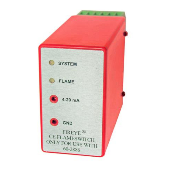
The MBCE-110/230FR modules provide visual indication and electrical outputs that
signal the user regarding flame presence in a combustion chamber. The module uses
Fireye flame rods to sense flame presence independently or as components in a burner
management system. Many operational characteristics are provided including:
•
CE approved
•
Self-contained: 110 VAC, 50/60 Hz: MBCE-110FR-1, MBCE-110FR-3
•
Flame Rod compatible
•
Flame ON/OFF LED indicator
•
4-20mA permits direct reading of flame signal strength
•
Uses CE approved 11-pin relay base
•
Panel surface or DIN-rail mounting
•
Self-check
The unit provides a cost effective, self-checking method of monitoring flames using
the ionization principle.
Check with Fireye for more details by contacting your local distributor or by check-
ing the Fireye home page at www.fireye.com.
NOTE: When the MBCE-110/230FR modules are used, additional means must be furnished to provide
those functions usually provided by flame safeguard control systems to meet local regulations (i.e.:
safe start checks, valve closure, starting and running interlocks, safety timings, etc.).
WARNING: The Equipment described in this manual is capable of causing property damage, severe
injury, or death. It is the responsibility of the owner or operator to ensure that the equipment
described is installed, operated, and commissioned in compliance with the requirements of all
national and local legislation, which may prevail. Installation, commissioning, or adjustment of this
product MUST be carried out by suitably trained engineer or personnel qualified by training or
experience.
NOTICE: When Fireye products are combined with equipment manufactured by others and/ or
integrated into systems designed or manufactured by others, the Fireye warranty, as stated in its
General Terms and Conditions of Sale, pertains only to the Fireye products and not to any other
equipment or to the combined system or its overall performance.
© 2023 Carrier
230 VAC, 50/60 Hz: MBCE-230FR-1, MBCE-230FR-3
MBCE-110/230FR
Flame Sensor
Module
exida
F M E D
S I L 2
SEE NOTE 1 ON PAGE 4
MBCE-1001
May 11, 2021
1
Advertisement

Subscribe to Our Youtube Channel
Related Manuals for Fireye MBCE-110FR-1


Summary of Contents for Fireye MBCE-110FR-1
- Page 1 Fireye warranty, as stated in its General Terms and Conditions of Sale, pertains only to the Fireye products and not to any other equipment or to the combined system or its overall performance.
- Page 2 ORDERING INFORMATION PART NUMBER DESCRIPTION BULLETIN Flame Sensor MBCE-110FR-1 MBCE-1001 Single channel module, 110 VAC 50/60 Hz, use with flame rod, 1 sec. FFRT. MBCE-110FR-3 Single channel module, 110 VAC 50/60 Hz, use with flame rod, 3 sec. FFRT. MBCE-1001...
- Page 3 PRODUCT SPECIFICATIONS (CEX Models) Supply Voltage: MBCE-110FR-CEX - 110 VAC (+10%, -15%), 50/60 Hz (@ 0.1 Amp consumption) MBCE-230FR-CEX - 230 VAC (+10%, -15%), 50/60 Hz (@ 0.05 Amp consumption) Flame Relay Output: SPDT 2 Amp Resistive @ 110VAC, 1 Amp @ 30VDC SPDT 1 Amp Resistive @ 230VAC, 1 Amp @ 30VDC Flame Fail Response Time: 1 or 3 seconds - depending on part number (-1, -3)
- Page 4 DIN CERTCO Registration # 5F234 Note 1: Based on Exida’s FMEDA report no. FIR 09/10-26 R001 dated December 13, 2010, Fireye certifies that the MBCE Flame Sensor Modules are suitable for installations up to and including SIL2 Example of product label...
- Page 5 SENSOR INSTALLATION WARNING: Incorrect flame rod installation may result in the generation of a false flame signal, causing unburned fuel to collect in the combustion chamber. The result can be explosions, injuries and property damage. Be certain that the flame rod detects only pilot and/or main flames.
- Page 6 WIRING BASE PINOUT INFORMATION The following table shows the wiring information and the ratings. To guarantee proper operation, the unit MUST NOT be operated above its maximum rating. TERMINAL NO. TERMINAL NAME DESCRIPTION DIRECTION RATING (11) OPEN UNUSED (A1) 4-20mA COM 4-20mA COMMON LOCAL GROUND...
- Page 7 4-20mA measurements can be taken from the test jack connector located at the faceplate of the unit. Measurements can also be taken using the dedicated 4-20mA OUT & 4-20mA COM terminals located at the wiring base. NOTE: The 4-20mA return path is labeled “GND” on the faceplate. This is simply a local return path for the 4-20mA current, and it MUST NOT be attached or referenced to earth ground or other forms of ground connection.
- Page 8 When Fireye products are combined with equipment manufactured by others and/or integrated into systems designed or manufactured by others, the Fireye warranty, as stated in its General Terms & Conditions of Sale, pertains only to the Fireye products and not to any other equipment or to the combined system or its overall performance.
Need help?
Do you have a question about the MBCE-110FR-1 and is the answer not in the manual?
Questions and answers