Ricoh AficioSP C410DN Hardware Manual
Ricoh aficiosp c410dn: hardware guide
Hide thumbs
Also See for AficioSP C410DN:
- Software manual (354 pages) ,
- Quick reference manual (9 pages) ,
- Quick installation manual (4 pages)
Table of Contents
Advertisement
Read this manual carefully before you use this machine and keep it handy for future reference. For safe and correct use, be sure to read the
Safety Information before using the machine.
Guide to the Printer
1
Installing Options
2
Connecting the Printer
3
Configuration
4
Paper and Other Media
5
Replacing Consumables and Maintenance Kit
6
7
Cleaning the Printer
Adjusting the Printer
8
9
Troubleshooting
Removing Misfed Paper
10
Appendix
11
Hardware Guide
Advertisement
Table of Contents
Troubleshooting

Related Manuals for Ricoh AficioSP C410DN


Summary of Contents for Ricoh AficioSP C410DN
- Page 1 Read this manual carefully before you use this machine and keep it handy for future reference. For safe and correct use, be sure to read the Safety Information before using the machine. Guide to the Printer Installing Options Connecting the Printer...
- Page 3 ® The Bluetooth word mark and logos are owned by the Bluetooth SIG, Inc. and any use of such marks by Ricoh Company, Ltd. is under license. NetWare is a registered trademark of Novell, Inc. PictBridge is a trademark. Other product names used herein are for identification purposes only and might be trademarks of their respective companies.
- Page 4 High temperature parts. Turn off the main power and be careful when replacing fusing unit/removing misfed paper. The inside of this printer becomes very hot. Do not touch parts labelled “v” (in- dicating a hot surface). Touching these parts will result in burns.
- Page 5 Do not incinerate used toner or toner containers. Toner dust might ignite when exposed to an open flame. Do not incinerate spilled toner or used toner. Toner dust is flammable and might ignite when exposed to an open flame. Disposal should take place at an authorized dealer or an appropriate collection site.
-
Page 6: Manuals For This Printer
Provides information on safe usage of this machine. To avoid injury and prevent damage to the machine, be sure to read this. ❖ Quick Installation Guide Contains procedures for removing the printer from its box, connecting it to a computer, and installing its driver. ❖ Hardware Guide Contains information about paper and procedures such as installing options, replacing consumables, responding to error messages, and resolving jams. -
Page 7: How To Read This Manual
How to Read This Manual Symbols This manual uses the following symbols: Indicates important safety notes. Ignoring these notes could result in serious injury or death. Be sure to read these notes. They can be found in the Safety Information. Indicates important safety notes. -
Page 8: Description For The Specified Model
This explains about the 120 V model printer. You can identify the model by checking the label on the rear of the printer. Read if you purchase this model. Note ❒ You can identify the printer's model by checking the label on the rear of the printer as shown. AQC065S... -
Page 9: Installing The Operating Instructions
“Setup.exe” to start the installation. ❒ To uninstall the Operating Instructions Manual, select [Programs] in the [Start] menu, select your printer driver, and then click [uninstall]. You can uninstall each Manual Guide separately. ❒ If you are using an incompatible Web browser and the simpler version of the Operating Instructions Manual does not display correctly, open the folder “MANUALLANG (language) \ (manual name) unv”... -
Page 10: Table Of Contents
TABLE OF CONTENTS Trademarks...i Positions of RWARNING and RCAUTION labels ... ii Manuals for This Printer... iv How to Read This Manual ...v Symbols ... v Description for the Specified Model... vi Installing the Operating Instructions ...vii 1. Guide to the Printer Exterior: Front View... - Page 11 Using DHCP - Detecting the Network Address Automatically...67 Making Network Settings for Using Netware... 69 IEEE 802.11b (Wireless LAN) Configuration ... 71 5. Paper and Other Media Paper and Other Media Supported by This Printer...77 Paper Recommendations... 81 Loading Paper... 81 Storing Paper ... 81 Types of Paper and Other Media ...82...
- Page 12 9. Troubleshooting Error & Status Messages on the Control Panel ... 155 Panel Tone... 157 Printer Does Not Print ... 158 Checking the port connection...160 Other Printing Problems ... 162 Additional Troubleshooting ... 168 10.Removing Misfed Paper Removing Misfed Paper ... 171 When the Paper Misfeed Message Appears (Cover A)...
-
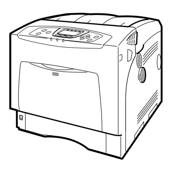
Page 13: Guide To The Printer
1. Guide to the Printer Exterior: Front View Control Panel Contains keys for printer control and a display that shows the printer status. Front Cover Open the front cover to replace the fusing unit or transfer roller, or to remove jammed paper. - Page 14 Note ❒ When setting paper larger than A5 K, pull out the paper extender as shown. For details about the sizes and types of paper that can be used, see p.77 “Paper and Other Media Supported by This Printer”. AQC022S...
-
Page 15: Exterior: Rear View
Ethernet Port Use a network interface cable to connect the printer to the network. USB Port Use a USB cable to connect the printer to the host computer. Optional Interface Board Slots Insert an optional IEEE 802.11b interface unit, wireless interface board, or 1284 in- terface board in this slot. -
Page 16: Inside
Guide to the Printer Inside Toner Cartridge Loads from the printer rear, in the order of yellow (Y), cyan (C), magenta (M), and black (K). If the message which prompts you to re- place toner appears on the screen, replace the indicated color of the toner cartridge. -
Page 17: Control Panel
Indicates whether the printer is online or offline. Press this to switch between on- line and offline. When the lamp is lit, the printer is online, enabling data reception from the host computer. When the lamp is unlit, the printer is of- fline, disabling data reception from the host computer. - Page 18 Guide to the Printer {OK} key Press this key to execute menu items se- lected on the display. {Escape} key Press this key to return to the previous condition on the display.
-
Page 19: Display Panel
“Ready”, “Offline”, and “Printing...”. [Option] Press to display the status of options in- stalled in the printer. Reading the Display and Using Keys This section explains how to read the display and using the selection key for the initial display. - Page 20 Guide to the Printer...
-
Page 21: Installing Options
Available Options This section describes how to install options. By installing options, you can improve the printer performance and have an ex- panded variety of features to use. For the specifications of each option, see p.182 “Specifications”. R CAUTION: • Before installing options, the machine should be turned off and unplugged for at least an hour. -
Page 22: Option Installation Flow Chart
Installing multiple options in the following order is recommended: Attach the paper feed unit (Paper Feed Unit Type 4000). Attach the paper feed units to the bottom of the printer. You can attach up to two paper feed units. Up to 1750 sheets of paper can be loaded in total. -
Page 23: Installing Options
Paper Feed Unit Type 4000 Loads up to 550 sheets of paper. Up to two paper feed units, can be in- stalled on the printer. Installed tray units are identified as “Tray 2” and “Tray 3”. See p.14 “Attaching Paper Feed Unit Type 4000”. - Page 24 IEEE 1284 Interface Board Type A, USB Host Interface Board Type A, and Gi- gabit Ethernet Board Type A. ❒ Some printer models come with the Expansion Hard Disk Drive Unit and Data Overwrite Security Unit installed as default. Reference For the specifications of each option, see p.182 “Specifications”.
-
Page 25: Caution When Re-Installing The Controller Board
This section describes handling the controller board when installing options. If you slide out the controller board to install the SDRAM module, the user ac- count enhance unit, or the printer hard disk, carefully follow the instruction be- low to re-install the controller board. -
Page 26: Attaching Paper Feed Unit Type 4000
When installing multiple options, install the paper feed unit first. R CAUTION: • The printer weights approximately 50 kg (110.3 lb.). When moving the print- er, use the inset grips on both sides, and lift slowly. The printer will break or cause injury if dropped. R CAUTION: •... - Page 27 Important ❒ The printer should always be lifted by at least two people. Align the printer with the two upright pins on the paper feed unit and then lower the printer slowly. When installing two paper feed units, connect the two units first using the same procedure below before connecting the units to the printer.
- Page 28 Installing Options Note ❒ When moving the printer, remove the paper feed unit. ❒ After finishing installation, you can check whether the paper feed unit is properly installed: Print the configuration page from the [List/Test Print] menu. If it is installed properly, “Tray 2” or “Tray 2”, “Tray 3” will appear for “Connection Equipment”...
-
Page 29: Attaching Memory Unit Type D 128Mb, Memory Unit Type E 256Mb (Sdram Module)
❒ Do not subject the memory unit to physical shocks. ❒ Available memory varies depending on a model type. ❒ Before using the new memory unit, Be sure to make settings in the printer driver. Turn off the power, and then unplug the power cable. - Page 30 Installing Options Grasp the handles and carefully pull out the controller board. Using both hands, slide the controller board completely out. Place the controller board on a flat surface, and then loosen the four screws to remove the cover. The screws cannot be fully removed. AQC640S AQC650S AQC660S...
- Page 31 Attaching Memory Unit Type D 128MB, Memory Unit Type E 256MB (SDRAM Module) Be sure to install the SDRAM module as shown. Two slots are provided for the SDRAM modules. The default SDRAM module is installed in the inner slot. To install an additional memory, attach an additional SDRAM module to the outer slot, or replace the default SDRAM module.
- Page 32 Fasten the four screws to attach the cover. Align the controller board with the left and right rails, and then push it carefully in, until it stops. The printer may malfunction if the controller board is not properly installed. AET078S AQC700S...
- Page 33 Attaching Memory Unit Type D 128MB, Memory Unit Type E 256MB (SDRAM Module) Fasten the controller board to the printer using the three screws. Note ❒ Be sure to return the provided screwdriver to its original position on the inside of the front cover.
-
Page 34: Attaching User Account Enhance Unit Type E
Installing Options Attaching User Account Enhance Unit Type E R CAUTION: • Do not touch the inside of the controller board compartment. Doing so may cause a malfunction or a burn. Important ❒ Before touching the User Account Enhance Unit, ground yourself by touch- ing something metal to discharge any static electricity. - Page 35 Grasp the handles, and then pull the controller board carefully out. Using both hands, slide the controller board completely out. Place the controller board on a flat surface. Loosen the five screws to re- move the cover The screws cannot be fully removed. Attaching User Account Enhance Unit Type E AQC640S AQC650S...
- Page 36 Installing Options Be sure to install the User Account Enhance Unit as shown. Align the notch of User Account Enhance Unit, and then insert it into the controller board, pressing it down until it clicks into place. Make sure that User Account Enhance Unit is firmly connected to the con- troller board.
- Page 37 Push on the area of the controller board that is marked “PUSH”. Push in the controller board until it can go no further. The printer may malfunction if the controller board is not properly installed. Fasten the controller board to the printer using the three screws.
- Page 38 Installing Options Note ❒ After finishing installation, you can check User Account Enhance Unit is properly installed: Print the configuration page from the [List/Test Print] menu. If it is installed properly, “Accounting Module” will appear for “De- vice Connection” on the configuration page. ❒...
-
Page 39: Attaching Hard Disk Drive Type 4000
Attaching Hard Disk Drive Type 4000 R CAUTION: • Do not touch the inside of the controller board compartment. Doing so may cause a machine malfunction or a burn. Important ❒ Before touching the hard disk drive, touch something metal to discharge any static electricity. - Page 40 Installing Options ❖ Power Cable ❖ Four Screws Turn off the power, and then unplug the power cable. Loosen the three screws securing the controller board. The screws cannot be fully removed. AET085S AET086S AQC630S...
- Page 41 Grasp the handles, and then pull the controller board carefully out. Using both hands, slide the controller board completely out. Place the controller board on a flat surface, and then loosen the four screws to remove the cover. The screws cannot be fully removed. Attaching Hard Disk Drive Type 4000 AQC640S AQC650S...
- Page 42 Installing Options Be sure to install the hard disk drive unit as shown. Use the screws supplied with the hard disk drive to secure the unit to the controller board. Connect the power cable to the hard disk drive and controller board. AET069S AET087S AET088S...
- Page 43 Push only on the area of the controller board that is marked “PUSH”. Push in the controller board until it can go no further. The printer may malfunction if the controller board is not properly installed. Attaching Hard Disk Drive Type 4000...
- Page 44 Installing Options Fasten the controller board to the printer using the three screws. When the power is turned on, the hard disk drive will be formatted automat- ically. Note ❒ After finishing installation, you can check whether the hard disk drive is properly installed: Print the configuration page from the [List/Test Print] menu.
-
Page 45: Attaching Ieee 802.11B Interface Unit
Attaching IEEE 802.11b Interface Unit R CAUTION: • Do not touch the inside of the controller board compartment. Doing so may cause a machine malfunction or a burn. Important ❒ Before touching the 802.11b interface unit, touch something metal to dis- charge any static electricity. - Page 46 Installing Options • Antenna Cap Turn off the power, and then unplug the power cable. Loosen the two screws and remove the cover of the 802.11b interface unit installation unit. The removed cover is not used when installing the interface unit. Fully insert the 802.11b interface unit.
- Page 47 Attach the antenna to the card with the label facing down and the uneven side of the antenna facing up. With the antenna and the indented end toward you, slowly insert the inter- face card until it stops. Hold the antenna cap with the cut off corners towards you and fit it over the card. Note ❒...
-
Page 48: Attaching Bluetooth Interface Unit Type 3245
• Do not touch inside the controller board compartment. Doing so may cause a machine malfunction or a burn. Important ❒ When using the printer with the Bluetooth interface unit installed, Bluetooth needs to be installed on the computer. ❒ Before manipulating the Bluetooth interface unit, touch something metal to discharge static electricity. - Page 49 • Antenna Cap Turn off the power, and then unplug the power cable. Loosen the two screws and remove the cover of the Bluetooth interface unit installation unit. The removed cover is not used when installing the interface unit. Fully insert the Bluetooth interface unit. Tighten the two screws to secure the interface unit.
- Page 50 Installing Options With the “INSERT” side facing you, slowly insert the card into the Blue- tooth interface unit until it stops. Press the antenna to extend it. Holding the antenna cap with the two cut-off corners toward you, fit the cap over the card.
-
Page 51: Attaching Ieee 1284 Interface Board Type A
Attaching IEEE 1284 Interface Board Type A R CAUTION: • Do not touch inside the controller board compartment. Doing so may cause a machine malfunction or a burn. Important ❒ Before handling the 1284 interface board, touch something metal to discharge static electricity. - Page 52 Installing Options Fully insert the 1284 interface board. Confirm that the 1284 interface board is firmly connected to the controller board. Tighten the two screws to secure the 1284 interface board. Note ❒ Use the supplied adaptor to make the connection with the computer. ❒...
-
Page 53: Attaching The Usb Host Interface Board Type A
Attaching the USB Host Interface Board Type A Important ❒ When connecting a digital camera to the printer via USB, the USB port of the USB host interface board is required. ❒ Before handling the USB host interface board, ground yourself by touching something metal to discharge any static electricity. - Page 54 Installing Options Fully insert the USB host interface board. Tighten the two screws to secure the USB host interface board. Check the USB host interface board is inserted firmly to the controller board. Note ❒ After finishing installation, check the USB host interface board is installed properly: print the configuration page from the [List/Test Print] menu.
-
Page 55: Attaching Gigabit Ethernet Board Type A
Attaching Gigabit Ethernet Board Type A Important ❒ The printer's ethernet and USB ports are not available when the gigabit eth- ernet board is attached to the printer. Instead, you can use the ethernet port and USB port mounted on the board. - Page 56 Installing Options Turn off the power, and then unplug the power cable. Disconnect the cables from the ethernet port and the USB port of the print- er, and cover each port with its protective cap. Loosen the two screws and remove the cover of the Gigabit ethernet board installation unit.
- Page 57 Tighten the two screws to secure the Gigabit ethernet board. Check the Gigabit ethernet board is connected firmly to the controller board. Note ❒ After finishing installation, check the Gigabit ethernet board is installed properly: print the configuration page from the [List/Test Print] menu. If it is installed properly, you will see “Gigabit Ethernet Board”...
-
Page 58: Attaching Data Overwrite Security Unit Type E
Installing Options Attaching Data Overwrite Security Unit Type E Important ❒ Protect the Data Overwrite Security unit from physical shocks. ❒ Use the right slot for the Data Overwrite Security unit. Check the package contains the following: ❖ Data Overwrite Security unit Turn off the power, and then unplug the power cable. - Page 59 Reattach the cover over the Data Overwrite Security unit. Fasten the screw to secure the cover. Note ❒ Do not touch the Data Overwrite Security unit while the printer is in use. It may come loose, even if pushed only slightly. Attaching Data Overwrite Security Unit Type E...
-
Page 60: Attaching The Camera Direct Print Card
Installing Options Attaching the Camera Direct Print Card Important ❒ Protect the Camera Direct Print card from physical shocks. ❒ Use the right slot for the Camera Direct Print card. Check the package contains the following: ❖ Camera Direct Print Card Turn off the power, and then unplug the power cable. - Page 61 Reattach the cover over the Camera Direct Print card. Fasten the screw to se- cure the cover. Note ❒ Do not touch the Camera Direct Print card while the printer is in use. It may come loose, even if pushed only slightly. Attaching the Camera Direct Print Card...
-
Page 62: Attaching Vm Card Type D
Installing Options Attaching VM Card Type D Important ❒ Protect VM Card Type D from physical shocks. ❒ Use the right slot for the VM card. Check the package contains the following: ❖ VM Card Type D Turn off the power, and then unplug the power cable. Remove the cover of the controller board's center expansion card slot. - Page 63 Reattach the cover over the VM card. Fasten the screw to secure the cover. Note ❒ Do not touch the VM card while the printer is in use. It may come loose, even if pushed only slightly. AQC107S Attaching VM Card Type D...
-
Page 64: Attaching Data Storage Card Type A
Installing Options Attaching Data Storage Card Type A Important ❒ Protect Data Storage Card Type A from physical shocks. ❒ Use the right slot for the Data Storage card. Check the package contains the following: ❖ Data Storage Card Type A Turn off the power, and then unplug the power cable. - Page 65 Reattach the cover over the Data Storage card. Fasten the screw to secure the cover. Note ❒ Do not touch the Data Storage card while the printer is in use. It may come loose, even if pushed only slightly. Attaching Data Storage Card Type A...
- Page 66 Installing Options...
-
Page 67: Connecting The Printer
❒ The Ethernet cable is not supplied with this printer. Select your cable accord- ing to the network environment. Attach one ferrite core at the printer end of the Ethernet cable, and then at- tach the other ferrite core about 10 cm (4 inches) ( ) from this core. - Page 68 The printer's ethernet and USB ports are not available when the gigabit eth- ernet board is attached to the printer. Connect the other end of the cable to the printer's network, such as a hub. Note ❒ The printer's ethernet and USB ports are not available when the gigabit ethernet board is attached to the printer.
-
Page 69: Reading The Led Lamps
TX is being used. It comes off when 10BASE-T is being used. ❖ For gigabit ethernet board Green: comes on when 10BASE-T is being used. AQC070S Green: comes on when the printer is properly connected to the net- work. AQC070S Yellow: comes on 100BASE-TX is being used. -
Page 70: Usb Connection
Server 2003, Mac OS 9.x, and Mac OS X. ❒ Windows 98SE/Me supports USB1.1 speeds. ❒ USB connection with Macintosh is only possible via the printer's USB port. Connect the square-shaped connector of the USB2.0 cable to the USB port. -
Page 71: Connecting A Digital Camera
❒ Make sure your digital camera supports PictBridge. Attach the hook on the back of the printer near the USB connection slot. Attach the hook where it will not interfere with printer operation and access. - Page 72 Connecting the Printer Use the USB cable supplied with the USB host interface board to connect the printer and the digital camera. Connect the flat connector of the USB ca- ble to the USB host interface board. Connect the square-shaped connector on the opposite end of the USB cable to the digital camera.
-
Page 73: Parallel Connection
Parallel Connection Important ❒ The parallel interface cable is not supplied with the printer. ❒ The printer's parallel connection is a standard bidirectional interface that re- quires an IEEE 1284-compliant 36-pin parallel cable and host computer paral- lel port. ❒ Use shielded interface cable. Unshielded cables create electromagnetic inter- ference that could cause malfunctions. - Page 74 Connecting the Printer...
-
Page 75: Configuration
You can use SmartDeviceMonitor for Admin or a Web browser to make IP ad- dress-related settings in a TCP/IP-capable environment. Important ❒ Configure the printer for the network using the control panel. ❒ The following table shows the control panel settings and their default values. These items appear in the “Host Interface” menu. - Page 76 Configuration Press the {Menu} key. Select [Host Interface] using {T} or {U}, and then press the {OK} key. Select [Network] using {T} or {U}, and then press the {OK} key. Select [Effective Protocol] using {T} or {U}, and then press the {OK} key. Select the network protocol using {T} or {U}, and then press the {OK} key.
- Page 77 6/6.5. Press the {Escape} key until the screen returns to the [Network] menu. If you use IPv4, assign the IPv4 address to the printer. Select [Machine IPv4 Address] using {T} or {U}, and then press the {OK} key. To get the IP address for the printer, contact your network administrator.
- Page 78 Configuration Select [Specify] using {T} or {U}, and then press the {OK} key. If you do not select [Specify] in this step, the address you set will not be saved. Press the {Menu} key to return to the initial screen. Print a configuration page to confirm the settings made.
-
Page 79: Using Dhcp - Detecting The Network Address Automatically
Using DHCP - Detecting the Network Address Automatically Important ❒ When you use this printer in DHCP environment, select [Auto-Obtain (DHCP)] following this procedure. ❒ When [Auto-Obtain (DHCP)] is selected, you cannot make settings for the fol- lowing items: • IP Address •... - Page 80 Configuration Select [Auto-Obtain (DHCP)] using {T} or {U}, and then press the {OK} key. The address detected by the printer will appear. To check the detected addresses, press the followings: • [IP Add.] IP address • [Subnet M] Subnet Mask •...
-
Page 81: Making Network Settings For Using Netware
If your network can use more than two frame types, the printer may fail to select the correct frame type if [Auto Select] is selected. In this case, select the appropriate frame type. - Page 82 Configuration Select [NW Frame Type] using {T} or {U}, and then press the {OK} key. Select the frame type using {T} or {U}, and then press the {OK} key. Press the {Menu} key to return to the initial screen. Print a configuration page to confirm the settings made. Reference For details about printing the configuration page, see “Test Printing”, Quick Installation Guide.
-
Page 83: Ieee 802.11B (Wireless Lan) Configuration
IEEE 802.11b (Wireless LAN) Configuration Configure the printer to use IEEE 802.11b (Wireless LAN). The following table shows the control panel settings and their default values. These items appear in the [Host Interface] menu. Setting Name Communication Mode Channel Communication Speed... - Page 84 Configuration Select [IEEE 802.11b] using {T} or {U}, and then press the {OK} key. Select [Communication Mode] using {T} or {U}, and then press the {OK} key. Select the transmission mode of IEEE 802.11b using {T} or {U}, and then press the {OK} key.
- Page 85 Set [Communication Speed] in the same way. The factory default is [Auto Select]. If you need to change the transmitting speed depending on environment you are using, select the appropriate trans- mitting speed. Print a configuration page to confirm the settings made. Reference For details about printing the configuration page, see “Test Printing”, Quick Installation Guide.
- Page 86 Configuration Reference SSID can also be set using a Web browser. For details, see the Web Image Monitor Help, and “Configuring the Network Interface Board Using Web Browser”, Software Guide. WEP key can also be set using a Web browser. For details, see Web Image Monitor Help.
- Page 87 Enter the characters using {V}, or {W}, and then press the {OK} key. You can switch among upper/lower cases, numeric codes, and symbols by pressing [ABC/123]. When using 64 bit WEP, up to 10 characters can be used for hexadecimal and up to five characters for ASCII.
- Page 88 Configuration...
-
Page 89: Paper And Other Media
Printer This section describes the paper size, feed direction, and the maximum amount of paper that can be loaded into each paper tray in this printer. Note ❒ The following symbols and terminology are used to represent the feed direction. - Page 90 The size is supported, but it should be set as a custom size using the control panel. The supported size may differ depending on the printer language you use. Set as a custom size setting using the control panel. The following sizes are supported: •...
- Page 91 The size is supported, but it should be set as a custom size using the control panel. The supported size may differ depending on the printer language you use. Set as a custom size setting using the control panel. The following sizes are supported: Paper and Other Media Supported by This Printer 8.26 ”...
- Page 92 Paper and Other Media • Tray 1: approximately 3.94 - 8.5 inches in width, and 5.83 - 14 inches in length. • Bypass Tray: approximately 2.76 - 8.5 inches in width, and 5.83 - 35.43 inches in length. • Paper Feed Unit (Tray 2/3): approximately 3.94 - 8.5 inches in width, and 8.27 - 14 inches in length.
-
Page 93: Paper Recommendations
Paper Recommendations Loading Paper Important ❒ Do not use ink-jet printer paper because it may stick to the fusing unit and cause a paper misfeed. ❒ When printing on OHP transparencies that have a print side, load them with the print side over on the bypass tray. Not taking this precaution may cause them to stick to the fusing unit and cause misfeeds. -
Page 94: Types Of Paper And Other Media
When printing on the reverse side of plain paper that is already printed on, select [Plain: Dup.Back] from [Paper Type:] using the con- trol panel or printer driver. • Press the {Menu} key, select [Paper Input] , and then select [Letterhead] for the selected tray's paper type. - Page 95 Printer driver setup Duplex Printing Note ❒ If the printing result is badly wet or smudged, change the setting on the printer's control panel as the following: • Press the {Menu} key, select [Maintenance], [General Settings], and then select [Coated Paper]. Select one from [Coated Paper 1], [Coated Paper 2], [Coated Pa- per 3], or [Coated Paper 4].
-
Page 96: Thick Paper
• When printing on the reverse side of thick paper that is already printed on, select [Thick 1: Dup.Back] or [Thick 2: Dup.Back] from [Paper Type:] using the control panel or printer driver. 52 - 60.2 g/m (14 - 16 lb.) Make the following settings using the control panel: •... - Page 97 Additional cautions • Print speed for OHP transparencies is slower than for plain paper. • Due to switching modes, the printer will be on standby for • We recommend that you use a 4000 ANSI lumen or brighter Paper] for the selected tray's paper type.
- Page 98 Duplex printing Additional cautions Note ❒ If the printing result is badly wet or smudged, change the setting on the printer's control panel as the following: • Press the {Menu} key, select [Maintenance], [General Settings], and then select [Envelope]. Select one from [Envelope 1], [Envelope 2], [Envelope 3], or [Enve- lope 4].
-
Page 99: Paper Not Supported By This Printer
Paper not supported by this printer Avoid using the following paper as they are not supported by this printer. • Paper meant for an ink-jet printer • Bent, folded, or creased paper • Curled or twisted paper • Torn paper •... -
Page 100: Print Area
Paper and Other Media Print Area The following shows the print area for this printer. Be sure to set the print margins correctly by the application. ❖ Paper Print area Feed direction Approx. 4.2 mm (0.17 inches) Approx. 4.2 mm (0.17 inches) Note ❒... -
Page 101: Loading Paper
Loading Paper This describes how to load paper into the paper tray and bypass tray. R CAUTION: • Do not pull out the paper tray forcefully. If you do, the tray might fall and cause an injury. Loading Paper in Tray 1 and the optional paper feed unit The following example explains loading procedure for the standard paper tray (Tray 1). - Page 102 Lift the front of the paper tray (Tray 1), and slowly slide the paper tray back in, until it stops. Make sure the tray is fully inserted to prevent a paper misfeed. Reference For details about paper types supported by the printer, see p.81 “Paper Recommendations” , 20 lb., or thicker, slide the switch...
- Page 103 Setting a Paper Size by Using the Control Panel To load paper whose size cannot be selected automatically, set the paper size on the control panel. Follow the procedure described below to set the paper size. Press the {Menu} key. Select [Paper Input] using {T} or {U}, and then press the {OK} key.
- Page 104 Paper and Other Media Press the {Menu} key to return to the initial screen. Setting the Paper Size Automatically Important ❒ If you specify the paper size using the control panel, and want to return the settings to load paper size automatically, load paper into the paper tray, and follow this procedure.
- Page 105 Press the {Menu} key to return to the initial screen. Note ❒ Some paper sizes are not selected automatically. Check the followings, de- pending on the printer model: • Paper sizes not selected automatically for Tray 1 are: × 8 B5K, B6K, 5 ×...
- Page 106 • Optional paper feed unit (Tray 2, Tray 3): 100 - 216 mm (3.94 - 8.5 in.) in width and 210 - 355.6 mm (8.27 - 14 in.) in length. ❒ The printer cannot print from applications that do not support custom size paper. Press the {Menu} key.
- Page 107 Select [Custom Size] using the scroll keys, and then press the {OK} key. • • Enter the vertical value using {T} or {U}, and then press the {OK} key. Enter the horizontal value using {T} or {U}, and then press the {OK} key. Press the {Menu} key to return to the initial screen.
- Page 108 Paper and Other Media Specifying a Paper Type for Tray 1 and the Optional Paper Feed Unit Improve printer performance by selecting the optimum paper type for the tray. You can select from the following paper types: • Plain Paper, Recycled Paper, Special Paper 1, Special Paper 2, Special Paper 3,...
-
Page 109: Loading Paper In The Bypass Tray
❒ Set the size and direction of the loaded paper on the control panel or with the printer driver. Make sure the settings do not conflict. Otherwise, the paper may jam or the print quality may be affected. - Page 110 Paper and Other Media If you load A5 or larger size paper, pull out the bypass tray extension, and then flip it open. Slide the side guides outward, and then load paper print side down, until it stops. Adjust the side guides to fit the paper width. AQC004S AQC005S AQC006S...
- Page 111 Specifying Standard Size Paper for the Bypass Tray This describes how to load standard size paper into the bypass tray. Set the paper size using the control panel. Press the {Menu} key. Select [Paper Input] using {T} or {U}, and then press the {OK} key. Select [Paper Size: Bypass] using {T} or {U}, and then press the {OK} key.
- Page 112 ❒ Paper sizes between 140 - 900 mm in length and 70 - 216 mm in width can be loaded in the bypass tray. However, the printer can be set to print on paper up to 680 mm in length when using the RPCS printer driver, 677 mm when using the PS3 printer driver, and 432 mm when using the PCL printer driver.
- Page 113 1 mm. Enter the horizontal value using {T} or {U}, and then press the {OK} key. Press the {Menu} key to return to the initial screen. Reference For details about the printer driver, see the printer driver Help. Loading Paper...
- Page 114 Paper and Other Media Specifying a Paper Type for the Bypass Tray By selecting the paper type you want to load, the printer performs better. You can select from the following paper types: • Plain Paper, Recycled Paper, Special Paper 1, Special Paper 2, Special Paper 3,...
- Page 115 Select the paper type using {T} or {U}, and then press the {OK} key. Press the {Menu} key to return to the initial screen. Note ❒ If the printing result is wet or smudged with the [Plain Paper] setting, Make the following settings using the control panel: •...
-
Page 116: Switching Between Paper Trays
When paper of the same size is loaded in both the standard tray and the paper feed unit (option), and when [Auto Tray Select] is set with the printer driver, paper will be fed from the standard tray when you start printing. To print on paper loaded in the paper feed unit, switch the tray to be used to the paper feed unit using [Tray Priority] in the [Paper Input] Menu. -
Page 117: Replacing Consumables And Maintenance Kit
6. Replacing Consumables and Maintenance Kit Replacing the Toner Cartridge R WARNING: • Do not incinerate spilled toner or used toner. Toner dust is flammable and might ignite when exposed to an open flame. • Do not store toner, used toner, or toner containers in a place with an open flame. - Page 118 • If cyan, magenta, or yellow toner runs out, you can print in black and white using black toner. Change the color mode setting to Black and White using the printer driver. • If black toner runs out, you cannot print in black and white or color until the black toner cartridge is replaced.
- Page 119 Remove the toner cartridge you want to replace. Turn the locking lever of the toner cartridge towards the triangle mark ( ), and then lift out the toner cartridge ( ). • Do not shake the removed toner cartridge. Remaining toner may leak. •...
- Page 120 Note ❒ Cooperate with the Toner cartridge Recycling Program, whereby are col- lected used toner cartridges. For details, consult with the dealer where you purchased the printer, or with a sales or service representative. AQC009S AQC011S...
-
Page 121: Replacing The Photo Conductor Unit
❒ Do not pull out the photo conductor unit with force or haste - it may fall and you may damage the printer. ❒ Take care that nothing comes into contact with the surface of the photo conductor. - Page 122 Replacing Consumables and Maintenance Kit Turn the two green levers counterclockwise ( ), and then slowly open the inner cover ( ). The photo conductor units are installed as shown. From the right, the units are attached in the order of black (K), magenta (M), cyan (C), and yellow (Y). Remove the photo conductor unit you want to replace.
- Page 123 Pull out the ring pull handle of the photo conductor unit. Hook your finger through the ring pull handle, and then slowly pull out the photo conductor unit. When you have pulled the unit half way out, sup- port the photo conductor unit using your other hand, and then pull the unit completely out.
- Page 124 Replacing Consumables and Maintenance Kit Remove the protecting cover. Do not remove the tape yet. Check the installation position of the photo conductor unit. Install the unit where the colored labels correspond. Install the photo conductor unit with the tape still attached. Align the tip of the photo conductor unit with the opening, and then slowly insert the unit, until it stops.
- Page 125 Use a finger to push the label with three green lines, and then push in the photo conductor unit, until it clicks into position. If the installation fails, the small, pentagonal window turns red. Hold the photo conductor unit firmly in place, and then pull out the tape. •...
- Page 126 Carefully close the left cover. Plug in the power cable, and then turn on the power. The printer starts calibration. Wait until it stops. Wait until “Ready” appears on the display panel. Do not turn off the power during calibration. Doing so results in malfunction.
-
Page 127: Replacing The Intermediate Transfer Unit
Replacing the Intermediate Transfer Unit R CAUTION: • The inside of this printer becomes very hot. Do not touch parts labelled “v” (indicating a hot surface). Touching these parts will result in burns. ❖ When to replace the transfer unit •... - Page 128 Replacing Consumables and Maintenance Kit Carefully open the printer's front cover (A) by pulling the left and right side levers. Turn the green lever of the transfer unit counterclockwise to unlock the unit. Pull out the handle of the transfer unit. Grasp the handle and the green le- ver firmly, and then slowly pull out the transfer unit, until the green line marked on the upper surface of the unit appears.
- Page 129 When the green line appears, pull up the handles on the upper surface and support the transfer unit with your other hand. Grasp the raised up handles with both hands, and then pull the transfer unit completely out. • Use both hands and both handles when you pull out the unit. •...
- Page 130 The upper handles must be raised to insert the unit. When the upper handles touch the printer body, lower the handles, and then push in the transfer unit, until it stops. Turn the green lever clockwise to lock the unit.
- Page 131 Carefully close the left cover. Plug in the power cable, and then turn on the power. The printer starts calibration. Wait until it stops. Wait until “Ready” appears on the display panel. Do not turn off the power during calibration. Doing so results in malfunction.
-
Page 132: Replacing The Waste Toner Bottle
❒ Purchasing and storing extra waste toner bottles is recommended. Note ❒ Before removing the waste toner bottle from the printer, spread paper or some other material around the area to keep toner from dirtying your workspace. Prepare a new waste toner bottle. A new waste toner bottle is supplied with 6 seals (including one spare) and a plastic bag. - Page 133 Use the supplied seals to avoid toner spills before removing the filled waste toner bottle. Attach the seals to the five sponge pads, allowing them to act as covers. Slide the green lever to the unlock position. Lift the waste toner bottle with the seal still attached, and then remove the waste toner bottle from the left cover.
- Page 134 Replacing Consumables and Maintenance Kit Insert the projection part into the pivot inside the left cover, and then place the waste toner bottle in the horizontal position. The green lever will slide automatically when the waste toner bottle is set. Check the waste toner bottle is correctly locked.
-
Page 135: Replacing The Maintenance Kit
R CAUTION: • The inside of this printer becomes very hot. Do not touch parts labelled “v” (indicating a hot surface). Touching these parts will result in burns. • Grip the plug, not the cord, when pulling the plug from the socket. Pulling the cord causes wear and tear that can result in fire or electric shock. -
Page 136: Replacing The Friction Pad
Replacing Consumables and Maintenance Kit Replacing the Friction Pad Replace all the friction pads in the tray. The following procedure shows how to replace the tray's friction pad (Tray 1). Carefully slide the paper tray (Tray 1) out, until it stops. Then, lift the front slightly, and then pull the tray completely out. - Page 137 Turn the paper tray right way up, and remove the friction pad from the tray. The friction pad spring may come loose. Be careful not to lose the friction pad spring. Insert the new friction pad in the paper tray. Place the spring over the central prong of the new friction pad and align the friction pad with the grooves of the paper tray.
-
Page 138: Replacing The Paper Feed Roller
The following procedure shows how to replace the printer's paper feed rollers. R CAUTION: • The printer weights approximately 50 kg (110.3 lb.). When moving the print- er, use the inset grips on both sides, and lift slowly. The printer will break or cause injury if dropped. R CAUTION: •... - Page 139 If you have two paper feed units installed, also replace both paper feed rollers. Place paper in the paper trays and additional removed paper trays. Lift the front of the tray, and slide it carefully into the printer, until it stops. Replacing the Maintenance Kit...
-
Page 140: Replacing The Transfer Roller
Replacing Consumables and Maintenance Kit Replacing the Transfer Roller Carefully open the printer's front cover (A) of by pulling left and right side levers. Pinch the green clips on both ends of the transfer roller. Do not touch the roller area of the transfer roller. It may stain your hands or clothes. - Page 141 Insert the new transfer roller by placing its underside edge into the grooves shown in the illustration. Secure the transfer roller using the green fastening clips mentioned in step The transfer roller appears insecurely set, but this is intentional. Close the front cover (A). Replacing the Maintenance Kit AET165S AET166S...
-
Page 142: Replacing The Fusing Unit
R CAUTION: • The fusing unit becomes very hot. When installing a new fusing unit, turn off the printer and wait at least an hour. before replacing the old fusing unit. Not allowing the unit to cool may result in burns. - Page 143 Prepare a new fusing unit. Align the new fusing unit with the left and right rails. Push the fusing unit carefully in, until it stops. Then, pull up the fixing lever. Close the front cover (A). Replacing the Maintenance Kit AET183S AQC184S AQC181S...
-
Page 144: Replacing The Dustproof Filter
Replacing Consumables and Maintenance Kit Replacing the Dustproof Filter The dustproof filter is attached to the left side of the printer, as shown. Turn off the power, and then unplug the power cable. Use the grips on both sides to turn and then remove the dustproof filter cover. - Page 145 Attach the new dustproof filters to the covers at a time. The dustproof fil- ters are all the same size. Reattach the dustproof filter covers to the printer one at a time. Plug in the power cable, and then turn on the power.
- Page 146 Replacing Consumables and Maintenance Kit...
-
Page 147: Cleaning The Printer
❒ If there is dust or grime inside the printer, wipe with a clean, dry cloth. ❒ You must disconnect the plug from the wall outlet at least once a year. Clean away any dust and grime from the plug and outlet before reconnecting. -
Page 148: Cleaning The Friction Pad
Cleaning the Printer Cleaning the Friction Pad If the friction pad is dirty, a multi-feed or a misfeed might occur. In this case, clean the pad as follows: Slowly slide the paper tray (Tray 1) out, until it stops. After that, lift the front of the tray slightly, and then pull the tray completely out. - Page 149 Lift the front of the tray, and slide it carefully into the printer until it stops. Do not slide the paper tray in with force. If you do, the front and side guides might move. Note ❒ If misfeeds or multi-feeds of paper occur after cleaning the friction pad, contact your sales or service representative.
-
Page 150: Cleaning The Paper Feed Roller
R CAUTION: • When lifting the printer, use the grips on both sides of the printer, otherwise the printer might fall and cause personal injury. • When you move the printer, unplug the power cord from the wall outlet to avoid a fire or an electric shock. - Page 151 Slide the green lock lever to the right ( ), so that the paper feed roller can be released ( ). Wipe the rubber part of the roller with a soft damp cloth. After that, wipe it with a dry cloth to remove the water. Do not use chemical cleaner or organic solvent such as thinner or benzene.
- Page 152 Cleaning the Printer Move the printer back to its original position. Lift the front of the tray, and slide it carefully into the printer until it stops. Do not slide the paper tray in with force. If you do, the front and side guides might move.
-
Page 153: Cleaning The Registration Roller
Cleaning the Registration Roller R CAUTION: • The inside of this printer becomes very hot. Do not touch parts labelled “v” (indicating a hot surface). Touching these parts will result in burns. Clean the registration roller if dots (caused by specks of paper stuck to the roller) appear on printed OHP transparencies. - Page 154 Cleaning the Printer Clean the registration roller by applying a soft damp cloth while turning it. • Do not use chemical cleaners or organic solvents such as thinners or ben- zene. • Do not touch the belt of the transfer unit and transfer roller.
-
Page 155: Adjusting The Printer
8. Adjusting the Printer Adjusting the Color Registration After moving the printer, printing on thick paper, or printing repeatedly for some time, color degradation may occur. By performing color registration ad- justment, you can restore optimum print quality. If documents show color degradation after the printer is moved, perform auto- matic color adjustment. - Page 156 Adjusting the Printer On the cofirmation screen, press[OK]. Automatic color adjustment begins. Automatic color adjustment takes about 50 seconds. A confirmation message appears when complete. Press [Exit]. Press the {Menu} key to return to the initial screen.
-
Page 157: Correcting The Color Gradation
Correcting the Color Gradation Color gradation during color printing changes slightly, depending on a number of factors. If you print the same file repeatedly or toner was recently replaced, changes may occur in color tones. When this happens, to obtain suitable print re- sults, color gradation can be corrected, although it is not usually necessary to make any particular settings. -
Page 158: Set The Gradation Correction Value
Adjusting the Printer Set the Gradation Correction Value During printing, you can correct the gradation in two areas: bright part (high- light) and the medium (middle). The correction value for the highlight and the medium parts are set using [Print Sheet 1] and [Print Sheet 2] respectively. - Page 159 If you want to perform only auto color adjusting, select [Adjust Auto Density] using {T} or {U}, and then press the {OK} key. The confirmation message appears. press [OK]. When it is completed, the confirmation message appears. press [Exit]. In the Caribration menu, select [Print Sheet 1] or [Print Sheet 2] using {T} or {U}, and then press the {OK} key.
- Page 160 Adjusting the Printer Press [Result] to check the result by printing the calibration sheet. On the confirmation screen, press [Print]. After printing, press [Yes] to save the settings. After completing all settings, press the {Menu} key to return to the initial...
-
Page 161: Viewing The Color Calibration Sample Sheet And Gradation Correction Sheet
Viewing the Color Calibration Sample Sheet and Gradation Correction Sheet The color gradation correction value setting sheet contains two color sample col- umns “Sample 1” column for setting the highlight part, and “Sample 2” column for setting the medium part. Similarly, the gradation correction sheet contains: “Gradation correction sheet 1”... - Page 162 K (black), M (magenta), and C (cyan)/Y (yellow), determine the grada- tion correction and make settings using the control panel. Note ❒ XXXX represents the printer model name. K (black) correction values Adjust the printed color when only black toner is used. The currently set correction value is printed in red.
-
Page 163: Resetting The Gradation Correction Value To The Initial Value
Resetting the gradation correction value to the initial value Reset the correction value default. Press the {Menu} key. Select [Maintenance] using {T} or {U}, and then press the {OK} key. Select [Quality Maintenance] using {T} or {U}, and then press the {OK} key. Select [Colour Calibration] using {T} or {U}, and then press the {OK} key. -
Page 164: Adjusting Tray Registration
Adjusting the Printer Adjusting Tray Registration You can adjust the registration of each tray. The vertical adjustment is used for all trays. Normally, you need not update the registration. But when the optional paper feed unit or the duplex unit is installed, updating is useful in some cases. - Page 165 Select the tray you want to adjust using {T} or {U}, and then press the {OK} key. Print the test sheet to preview the settings. Confirm the position of the image on the test sheet, and then adjust the reg- istration value.
- Page 166 Adjusting the Printer Set the registration value (mm) using {T} or {U}, and then press the {OK} key. Increase the value to shift the print area in the positive direction, and decrease to shift in the negative direction. : Print Area : Feed Direction Pressing the {U} or {T} key makes the value increase or decrease by 1.0 mm...
-
Page 167: Troubleshooting
This is the default ready message. The printer is ready for use. No action is required. The printer is resetting jobs. Wait a while. The printer is setting changing. Wait a while. The printer is waiting for the next data to print. Wait a while. - Page 168 Controller Board. Only one toner cartridge is set. Set all the toner cartridges properly. The printer's self diagnostic test failed due to a loopback error. Replace the IEEE 1284 board that caused the error. For details, see p.39 “Attaching IEEE 1284 In- terface Board Type A”.
-
Page 169: Panel Tone
❒ Users cannot mute the printer's beep alerts. When the printer beeps to alert users of a paper jam or toner request, if the printer's covers are opened and closed repeatedly within a short space of time, the beep alert might continue, even after normal status has resumed. -
Page 170: Printer Does Not Print
If the cable is damaged or worn, replace it with a new one. See p.182 “Specifications”. If not blinking or lit, the data is not being sent to the printer. ❖ If the printer is connected to the computer using the in- terface cable Check the port connection setting is correct. - Page 171 Bluetooth interface unit. Memory Unit Type D 128MB, BIP If printing still does not start, contact your sales or service representative. Con- sult with the store where the printer was purchased for information about the location of sales or service representatives. Solutions and other devices.
-
Page 172: Checking The Port Connection
Windows 95/98/Me Click [Start], point to [Settings] and then click [Printers]. Click to select the icon of the printer. Next, on the [File] menu, click [Properties]. Click the [Details] tab. Check the [Print to the following port] box to confirm that the correct port is selected. - Page 173 Click [Printers and Other Hardware]. Click [Printers and Faxes]. Click to select the icon of the printer. Next, on the [File] menu, click [Properties]. Click the [Port] tab. Check the [Print to the following port(s).] box to confirm that the correct port is selected.
-
Page 174: Other Printing Problems
• Check the paper settings. See p.82 “Types of Paper and Other Media”. • Check the printer driver's paper settings. See the printer driver Help. When “Replace PCU:Black.” or “Replace PCU:Colour.” ap- pears on the display, replace the photo conductor unit. - Page 175 True Type fonts as an image. See the printer driver Help. If the printer is turned off while it is still accessing the hard disk (for example: during file deletion), the printer will re- quire more time to power-up the next time it is turned on.
- Page 176 • If an OHP transparency or glossy paper is being used, printing takes more time to start. • The printer was in the Energy Saver mode. To resume from the Energy Saver mode, the printer has to warm up, and this takes time until printing starts. To disable the En- ergy Saver mode, select [Off] for [Energy Saver] in the Sys- tem menu.
- Page 177 See p.109 “Replacing the Photo Conductor Unit”. • Condensation may have collected. If rapid change in tem- perature or humidity occurs, use this printer only after it has acclimatized. • Paper is damp. Use paper that has been stored properly.
- Page 178 When the message “Replace PCU:Black.” or “Replace PCU:Colour. ” appears, replace the photo conductor unit. See p.109 “Replacing the Photo Conductor Unit”. • When removing a jammed sheet, the inside of the printer may have become dirtied. Print several sheets until they come out clean.
- Page 179 Status PDF Direct Print is not executed (PDF file is not printed). As a result of printing using PDF Direct Printing, characters are missing or misshapen. The paper size appears on the control panel and printing is not performed with PDF Direct Print.
-
Page 180: Additional Troubleshooting
• Confirm [Notify by Email] is active in the System Menu on the Control Panel. See “System Menu”, Software Guide. • Access the printer through the Web browser, log on as an Administrator on the Web Image Monitor, and then con- firm the following settings in [Auto E-mail Notification]: •... - Page 181 Printing using Bluetooth is slow. Note ❒ If the printer is still not operating satisfactorily, contact your sales or service representative. Consult with the store where the printer was purchased for information about the location of sales or service representatives.
- Page 182 Troubleshooting...
-
Page 183: Removing Misfed Paper
❒ Toner on prints made after removing misfed paper may be loose (inadequate- ly fused). Make a few test prints until smudges no longer appear. ❒ Do not forcefully remove misfed paper, it will tear. Torn pieces remaining in- side the printer will cause further misfeeds and possibly damage the printer. -
Page 184: When The Paper Misfeed Message Appears (Cover A)
❒ Remove the paper from the bypass tray before opening the front cover. ❒ If a misfeed occurs when using the bypass tray, open the front cover, and then remove the misfed paper. Carefully open the printer's front cover (A) of by pulling left and right side levers. AQC018S... - Page 185 Remove misfed paper slowly. If you cannot find the misfed paper, look inside the printer. If a misfeed occurs in the output area of the fusing unit, open the output cover by pulling back the levers marked “A1” (left and right on the fusing unit's upper side).
- Page 186 Removing Misfed Paper Remove misfed paper slowly. Close the output cover of the fusing unit. Carefully close the front cover (A). If the error message remains displayed even you have removed the misfed paper, check the input tray for a paper misfeed. Pull out the paper tray, and then carefully remove any misfed paper.
-
Page 187: When The Paper Misfeed Message Appears (Cover Z)
A paper misfeed occurs in the duplex unit. Open the front cover (Z) to remove the misfed paper. Open the printer's front cover (Z) by pressing the button on the right side. Carefully remove misfed paper. Carefully close the front cover (Z). - Page 188 Removing Misfed Paper...
-
Page 189: 11. Appendix
• When moving the printer after use, do not take out any of the Toners, Photo Conductor Units, nor the Waste Toner Bottle to prevent toner spill inside the machine. -
Page 190: Moving The Printer
See Setup Guide and follow the steps backwards for removing options. Lift the printer with two people by using the inset grips on both side of the printer, and then move it horizontally to the place where you want to install If you removed options, reinstall them. -
Page 191: Consumables
❒ Toner cartridges (consumables) are not covered by warranty. However, if there is problem, contact the store where they were purchased. ❒ When you first use this printer, use the four toner cartridges packaged with the printer. ❒ Numbers of pages that can be printed using the toner cartridge supplied with... -
Page 192: Waste Toner Bottle
Appendix Waste Toner Bottle Name Waste Toner Bottle Type 145 A4/letter 5% test chart, 2 pages/ job, printing in monochrome/color only. Note ❒ The actual number of printable pages varies depending on the image volume and density, number of pages to be printed at a time, paper type and paper size used, and environmental conditions such as temperature and humidity. -
Page 193: Intermediate Transfer Unit (Transfer Unit)
❒ If the transfer unit is not changed when necessary, the quality of printing is not guaranteed. We recommend keeping a stock of transfer unit or purchas- ing one soon. Maintenance Kit ❖ Maintenance Kit Type 4000 (for the 25 ppm model printer) Name Fusing Unit Transfer Roller Paper Feed Roller ×... -
Page 194: Specifications
Monochrome: 10 sec or less (A4K/8 Color: 15 sec or less (A4K/8 Note ❒ If the printer has not been used for a while, there may be a short delay before the first page starts printing. ❖ Printing Speed: • The 30 ppm model printer... - Page 195 ❖ Warm-up Time: Less than 30 seconds (23 °C, 71.6 F) When no error is occurred. ❖ Dimensions: Printer only (tray not 446 mm (17.4 inches) 589.5 mm (23.2 inch- extended) ❖ Weight: Approximately 50 kg (110.3 lb.) (toner cartridges and power cord included)
- Page 196 • IEEE 802.11b (Wireless LAN) • Parallel (Bidirectional IEEE1284) • Bluetooth • Gigabit Ethernet (1000Base-T) • USB Host (1.1) ❖ Printer Language: RPCS, PCL 5c/6, PostScript Level 3, PDF, PictBridge ❖ Fonts: PCL 5c/6 Monotype Imaging 35 Intellifonts, 10 TrueType fonts, 13 International fonts, and 1 Bitmap font.
-
Page 197: Options
❒ You can install PostScript fonts with this optional hard disk drive. With Mac OS, types of fonts supported are PostScript Type 1 and PostScript Type 2. To download them, use Printer Utility for Mac. User Account Enhance Unit Type E ❖... - Page 198 Appendix Memory Unit Type D 128MB/Memory Unit Type E 256MB ❖ Module Type: SO-DIMM (Small Outline Dual-in-line Memory Module) ❖ Memory Type: SDRAM (Synchronous Dynamic RAM) ❖ Number of Pins: 200 pins IEEE 802.11b Interface Unit Type H ❖ Transmission Spec.: Based on IEEE 802.11b (Wireless LAN) ❖...
- Page 199 IEEE 802.11b Interface Unit Type I ❖ Transmission Spec.: Based on IEEE 802.11b (Wireless LAN) ❖ Protocol: IPv4, IPv6, IPX/SPX, AppleTalk Note ❒ SmartDeviceMonitor and Web Image Monitor are supported. ❖ Data Transfer Speed: Auto select from below speed 1 Mbps, 2 Mbps, 5.5 Mbps, 11 Mbps ❖...
- Page 200 Appendix Bluetooth Interface Unit Type 3245 ❖ Supported Profiles: • SPP (Serial Port Profile) • HCRP (Hardcopy Cable Replacement Profile) • BIP (Basic Imaging Profile) ❖ Frequency Range: 2.45 GHz ISM band ❖ Data Transmission Speed: 723 kbps Note ❒ The transmission speed is adjusted according to factors such as the dis- tance and obstacles between the devices, radio signal condition and Blue- tooth adaptor.
-
Page 201: Index
Caution when re-installing the controller board , 13 Cleaning the Friction Pad , 136 Cleaning the Paper Feed Roller , 138 Cleaning the Printer , 135 Cleaning the Registration Roller , 141 Configuration Ethernet Configuration , 63 IEEE 802.11b (Wireless LAN) - Page 202 Maintenance Kit , 123 , 181 Memory Unit , 186 Memory Unit (SDRAM module) , 9 , 17 Messages , 155 Moving and Transporting the Printer , 177 Network , 55 , 63 OHP transparencies , 85 Option Installation Flow Chart , 10...
- Page 203 Copyright © 2006...
- Page 204 Model Number: CLP30DN/CLP27DN/C7531dn/C7526dn/LP231cn/LP226cn/Aficio SP C411DN/Aficio SP C410DN EN USA G160-8611...
Need help?
Do you have a question about the AficioSP C410DN and is the answer not in the manual?
Questions and answers